ASM Metals HandBook Vol. 8 - Mechanical Testing and Evaluation
Подождите немного. Документ загружается.

Stress Field Condition Assumptions and Reconstruction
Engineers and research scientists have approached the measurement of residual stresses using destructive
methods with the aid of assumptions about the stress field conditions, including that the stresses in only one
axis are of interest, in order to simplify the measurement and reconstruction of the stress field. These have
included certain uniaxial, biaxial, and triaxial stress field assumptions.
Uniaxial Conditions. A procedure applicable only to the measurement of residual stresses in rods, cylinders,
and tubes, that is, components with axial symmetry, was reported by Heyn (Ref 23). In this work, it was
assumed that the stresses were axially symmetric and that only the longitudinal stresses were of interest. Thus,
the changes in length of the components (cylinders, rods, and tubes) were measured after removal of an axially
symmetric layer from the outside radius or boring out from an inside radius. The length of the component was
measured after each layer removal process, and this measurement was entered into various equations described
in the article. This procedure is called the Bauer-Heyn or Heyn-Bauer method (Ref 23) and is applicable only to
measuring longitudinal stresses in axially symmetric components. It does not measure radial or circumferential
stresses.
A second procedure assuming a uniaxial stress field, or that only the stresses in one axis are of interest, was
proposed by Stablein (Ref 24). Here the component was a bar with a rectangular cross section, and the residual
stresses acting along its length and varying through its thickness (smallest dimension) were measured. The
material from one face of the bar (one of the two faces with the largest area) was removed by milling.
Equations used to reconstruct the original stress field are described in the article. The depth of the removed
layer must be significantly greater than the depth of plastic deformation caused by the milling (see the section
“Sectioning and Material Removal Methods” in this article) and sufficient to cause a measurable bend in the
material. The length of the opposite face of the bar from where the material was removed is measured before
and after layer removal to determine the effect of the removal of the stressed layer. Presently this is usually
done using electrical resistance strain gages (see the section “Strain Measurement Methods”), but in the past it
was done by sensitive mechanical gaging techniques. This measurement can also be accomplished by
measuring the bend in the bar with suitable mechanical gages and fixtures; for example, a cantilever beam
approach. This procedure is applicable only to components of rectangular cross section where the stresses
parallel to the length are to be measured as they vary through the thickness.
Biaxial Conditions. A procedure applicable to axially symmetric components is the Mesnager-Sachs boring-out
technique (Ref 25, 26). The technique is applicable to cylindrical components with an axially symmetric
distribution of stresses. Here the change in length and diameter of the component is measured as material is
removed by axially boring-out material from the inside to produce a hollow cylinder. Presently biaxial electrical
resistance strain gages are usually attached to the outside of the component to measure the dimensional changes
in the axial and tangential directions. The strain change results are entered into equations described in two
articles (Ref 25, 26).
A procedure applicable to measuring biaxial residual stresses homogeneous over the planar surface of a flat
metal plate or sheet was proposed by Trenting and Read (Ref 27). It was based on uniformly removing thin
layers of the metal on one side of the sheet or plate and measuring the changes in curvature as the layers were
removed. It was assumed that the stresses were constant over the plane of the sheet or plate and varied only
through the thickness. Electrical resistance strain gages or mechanical gaging may be used to measure the
change in curvature.
Another procedure for measuring biaxial stresses homogeneous over the planar surface of a metal plate was
developed by Gunnert (Ref 28). This procedure assumes that a biaxial stress condition was uniform throughout
the depth of a circular groove that was milled around an elemental volume of material (trepanning) to render it
stress free. Thus, the strain change on only one surface was measured. The mechanical gaging technique
involved measuring the distance between each of four sets of shallow holes drilled in the element before the
groove was milled into the surface using a core drill. The distance between each set of holes was measured
before and after the groove was produced and provided the information necessary to calculate the original,
assumed biaxial residual stress condition parallel to the surface of the plate. Theoretically, only three sets of
holes are required to measure the biaxial stresses, but Gunnert used a fourth set to improve the accuracy. A
mechanical gage, termed an extensometer, was used to measure the distance between each set of holes. It
should be noted that this technique could be used to measure the gradient in the biaxial stress condition by
pausing in the milling operation at selected depths and measuring the distance between the holes at each groove
depth. Also, as with many of the older techniques, which originally applied mechanical strain gage apparatus,
electrical resistance strain gages or modern XRD stress instrumentation (instruments designed specifically for
stress measurement and not conventional XRD instruments modified with stress measurement accessories)
could be used. A procedure involving the drilling of a blind hole and electrical resistance strain gage is
somewhat similar to Gunnert's original technique and is described under semidestructive methods.
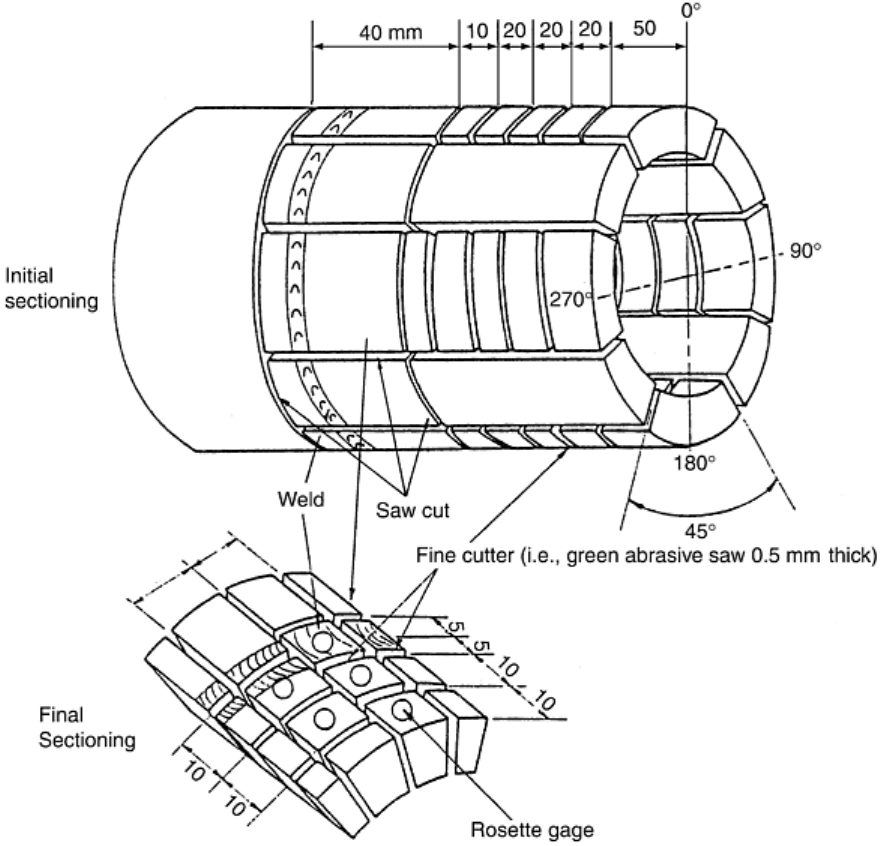
A more accurate procedure was later used to measure residual stresses in pipe weldments. Here the component
(pipe) was divided into a network (grid) of squares, and biaxial electrical strain gages were placed in the center
of each grid square on the outside diameter of the pipe (Ref 38). The pipe was then sectioned as shown in Fig. 4
into elements assumed to be stress-free, and the strain induced by the stress relief was read from the gages. In
placing the gages only on the outside diameter, the biaxial stress field was assumed to be uniform with depth;
however, had gages been placed on the inside and outside diameter, a more complete measurement of the stress
field could have been obtained, albeit assuming a linear variation in the residual stress from the outside to the
inside surface.
Fig. 4 Residual stress measurement of a girth welded pipe by strain gaging and sectioning. Note that
strain gages shown in the final sectioning should be placed on the pipe prior to initial sectioning. For a
more complete analysis, several of the layer sections detailed in the final sectioning step should be strain
gaged and sectioned (Ref 38).
A variation on the Gunnert procedure described in a previous paragraph was later published (Ref 5, 29). This
variation also was for application to plates and implied that the triaxial stress field could be measured by the
technique. It assumed that a homogeneous residual biaxial stress field, which varied with depth through the
plate thickness, existed. Four holes in a square pattern were drilled through the plate thickness. The distances
between all of the holes were then measured at selected hole depths. Next, a circular groove is milled in steps
of, for example, 2 mm around the drilled holes using a core drill as in Gunnert's original procedure (Ref 28).
The distance between the holes at the various depths was then measured at each core depth until the core was
milled completely through the plate. The cored plug was then assumed to be completely free of residual
stresses. The measured distances were then used to reconstruct the original biaxial stress condition of the plug
at each cored depth. A similar mechanical measuring gage was used in this technique as was used in Gunnert's
first technique (Ref 28).
Another approach to measuring residual stresses that has a broader application with respect to the shape of the
component and the stress field distribution was proposed by Rosenthal and Norton (Ref 30). It is applicable to
plates and plate-shaped weldments.
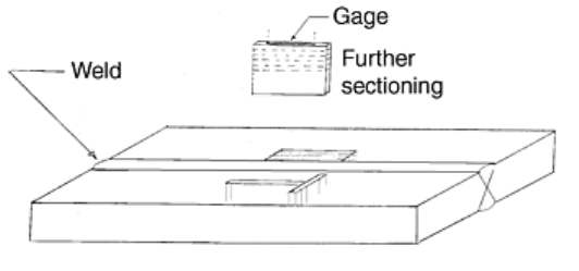
The procedure involved cutting two narrow blocks having the full thickness of the plate, each with its long axis
parallel to one of the assumed biaxial, principal residual stress directions in the surface of the plate (see the near
side of Fig. 5). Thus, the long axes of the blocks are perpendicular to each other and parallel to the face, the
largest area surface of the plate. The smallest dimension of the block should be several times smaller than the
thickness of the plate, and the largest dimension of the block should be at least twice the thickness. The block
then can be further sectioned in order to determine the biaxial stress variation through the thickness of the
component. This proceeds first by cutting the block at the location representing the midthickness of the
component plate and then by removing thin slices parallel to the original surface and from the bisected block as
shown in the upper part of Fig. 5.
Fig. 5 A welded steel plate, the near side of which shows the two narrow blocks suggested in Rosenthal
and Norton's (Ref 30) procedure. The far side shows several blocks sectioned to reveal the stresses
parallel to the weld with a gradient transverse to the weld.
The change in strain of the blocks is measured using shallow holes or dimples in the original surfaces of the
component. These gage points are located along the long axis of the block on the original faces of the plate (see
Fig. 5). The distance between these gage marks is measured before and after removal of the blocks from the
plate and after each sectioning of the block (Ref 30).
This procedure assumes a constant biaxial stress field over the length of the blocks, which is not the case in
welded plates in the direction transverse to the weld. The far side of the block in Fig. 5 shows a sectioning
procedure that would reveal the stresses parallel to the weld along a gradient transverse to the weld. Also,
electrical resistance strain gages could be used instead of measuring the distance between shallow holes or
dimples.
Another approach to a constant biaxial stress field in a flat plate, varying only through thickness, was described
by Moore and Evans (Ref 6). They relied on XRD for the measurement of the strains from which the stress was
calculated, and the procedure consisted of removing layers from the surface of the plate and measuring the
strains existing at each layer. The process assumed that the stress perpendicular to the surface was zero. It
should be noted that in order for this procedure to be valid, the XRD-measured areas would have to be free of
plastic deformation caused by layer removal (see the section “Sectioning and Material Removal Methods” in
this article).
Triaxial Conditions. In reality, in most components in which residual stresses have been induced, usually due to
manufacturing processes, the stress field is triaxial and varies from point to point (element to element) in all
three directions. Thus, a number of destructive procedures and stress field condition assumptions have been
applied in order to measure the three-dimensional residual stress field condition existing in most components of
practical engineering interest. Two of these are described in this section as follows.

Chen (Ref 31) revised Rosenthal and Norton's (Ref 30) approach to deriving the triaxial residual stress
condition. The typical method of residual stress measurement is by mechanically removing part of a body and
measuring the change of stress in the rest of the body. The method of Rosenthal and Norton instead deals only
with a small element that has been cut free from a plate. The sectioning procedure consists of removal of a
narrow block from a plate with gages attached, followed by splitting the block in half with gages attached on
the top and bottom surface of the block and successive slicing of both halves from the midsection to the outer
surface as shown in Fig. 5.
When the half-block is sliced to a thickness of 2.5 mm (0.1 in.), gages are removed and stresses are measured
(at at least two points) on the surface by XRD techniques. The basic assumptions of Rosenthal and Norton are
these: (a) partial relief of stress occurs in the direction of the long axis of the block, and a total relief of stress
occurs in the direction transverse to the long axis, (b) the small amount of stress relaxed in the remainder of the
block follows a linear law through the thickness when a thin slice of metal is removed, and (c) variation of
transverse stress along the axis of the weld is small in the middle portion of the plate weldment. The
determination of residual stresses may be divided into the steps described in the following paragraphs.
Determination is made of ε′
1
and ε′
t
, which represent the amount of strain relaxed in longitudinal and transverse
directions respectively, by cutting one longitudinal and one transverse block free from the plate. This is done by
determining the strain relief between two indentations on the top and bottom surface of each block using a
mechanical gage (see Fig. 5) and subtracting the gage readings on the blocks from the initial reading from the
plate. Note that this measurement also can be performed using electrical resistance strain gages or XRD (Ref
22, 33).
Determination is made of ε′
1
ε′
t
the strain relaxed on the top and bottom surfaces by splitting each block in half
and then successively slicing the blocks. Here again, measurements of the change are made by using
mechanical or electrical resistance strain gages or XRD.
Determination is made of the strain relieved (using at least two points) on the top and bottom surface using
sensitive mechanical gages to measure the distance between indentations and XRD after the thickness of the top
and bottom halves of the blocks has been reduced to 2.5 mm (0.1 in.). Note that the strain mechanical gages
were used because Rosenthal and Norton used conventional scanning x-ray instrumentation. With modern XRD
stress instrumentation (designed specifically for stress measurement, and not conventional XRD instruments
modified with stress measurement accessories), measurements can be made on any size of specimen (Ref 20,
22, 34, and 39).
Determination of the residual stress remaining in the top and bottom slices is made using XRD (an
enhancement of the Rosenthal and Norton procedure as suggested by Chen) (Ref 31). Here, the lattice strain
was measured in the remaining slices in at least two places near the gage points using XRD, and the absolute
residual stress remaining in the transverse and longitudinal directions respectively, S*
t
and S*
l
, was calculated
as described in the section “X-Ray Diffraction” in this article. These x-ray diffraction determined stresses
measured for each block were averaged and designated S*
t
or S*
l
for that face. The original stress S″, present
before slicing was determined by the following equations:
S″
t
= S*
t
+ Eε″
t
S″
l
= S* + Eε″
l
(Eq 1)
The total strain, ε″, may be obtained by dividing S″
t
or S″
l
by the modulus of elasticity, E.
Computation of Stress Relaxed by Cutting the Blocks from the Plate. Using the values of ε′ and ε″ obtained in
previous steps, the amount of longitudinal and transverse stress, S′
l
and S′
t
relaxed by cutting the blocks from
the plate was computed by means of the following equations:
(Eq 2)
where ν is Poisson's ratio. Equation 2 is valid for the case where the length of the block is at least twice the
thickness of the block. In case of shorter blocks, the following equations are used:

(Eq 3)
where β is the correction factor for a shorter block.
These values, when plotted for the top and bottom faces of the block and joined by a straight line, give the
stress, S′, relaxed by cutting the block from the plate.
Computation of Stress S″ Relieved by Splitting and Slicing the Blocks. This is done by means of the following
equations:
(Eq 4)
(Eq 5)
where α = fraction of the total thickness removed; ε″
t
, ε″
b
= relaxed strain measured on top and bottom surface
for position; and ε″
0
t
, ε″
0
b
= relaxed strain on the top and bottom surface when splitting the block in half.
Determination of total stresses relaxed across the thickness of the block in the longitudinal and transverse
directions is made by the following equations:
S
l
= S′
l
+ S″
l
S
t
= S′
t
+ S″
t
(Eq 6)
Determination of shearing stresses in the longitudinal and transverse directions is made by the use of the
following equation:
(Eq 7)
where S
w
and S
v
are the stresses measured in the direction w and v making angles +45° and -45° with the
longitudinal axis. However, if the biaxial stress condition is assumed, only the strain relief in one 45° direction
need be determined because the strain relief values would be equal. This requires that either a block at a 45°
angle to the longitudinal block be removed or that electric residual strain gage rosettes or XRD measuring at the
45° angle be used.
Determination of Stress in the Thickness Direction. The equilibrium equations may be written as the following:
(Eq 8)
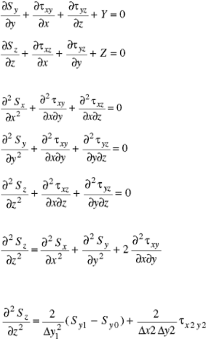
(Eq 9)
(Eq 10)
Differentiation of Eq 8, 9, and 10 with respect to x, y, z, respectively, yields:
(Eq 11)
(Eq 12)
(Eq 13)
Subtracting the summation of Eq 11 and 12 from Eq 13, results in:
(Eq 14)
Variation of S
x
along the x-axis is small in the middle portion of the plate; therefore, the first term in Eq 14 can
be neglected. Equation 14 can be approximated using the following:
(Eq 15)
where S
y0
= value of S
y
at the axis; S
y1
= value of S
y1
at a distance Δy1 on either side of the x axis; and τ
x2y2
=
value of τ
xy
at a distance Δx2 and Δy2 from the y axis and x axis respectively.
Therefore the stress in the thickness direction S
z
can be obtained through double integration with the boundary
condition that S
z
vanishes at both the top and bottom surfaces. In this way the entire triaxial residual stress state
was determined. Note that this procedure assumes that the residual stresses are uniform along the length of each
block.
A variation on Rosenthal and Norton's (Ref 30) method using electrical resistance strain gages or a
nondestructive technique such as XRD is as follows. The largest face of the blocks (described by the thickness
of the component or plate and the longest dimension of the blocks, Fig. 5) is divided into a two-dimensional
grid of elements. An electrical resistance strain gage is placed on each element, or a nondestructive
measurement such as XRD is performed. The block is sectioned along the grid lines to produce elements that
are assumed to be stress free. Note that if a nondestructive technique such as XRD is used, the plastically
deformed surface created by removing the block from the original component must be removed. This is best
done using electropolishing (see the section of this article “Sectioning and Material Removal Methods”). If
electropolishing of these cut faces is done to remove the plastic deformation and resultant residual stress
induced by a mechanical cutting procedure and XRD is applied, then the blocks need not be sectioned. The
measured XRD stress will provide the absolute residual stress field condition in the block, and, coupled with
the strain relieved by the original removal of the block from the plate, the entire triaxial residual stress
condition of the plate may be obtained.
This variation on Rosenthal and Norton's (Ref 30) method provides the information necessary to derive the
biaxial stress condition of each block, which can in turn be used to derive the triaxial condition of the original
plate. The stresses on each of the measured faces of the blocks must be measured in three directions to provide
the information necessary to obtain the principal stresses in the block faces in each element. Note that the strain
change caused by the sectioning of the blocks must be added to the strains measured in each element.
This procedure may be applied to a weldment with a single weld through its center as described by Rosenthal
and Norton (Ref 30), or to a more elaborate stress field, for example, where two orthogonal welds existed in the
component (plate). With a single weld, only the block-intersecting weld needs to be sectioned into elements,
because the residual stress field in the block parallel to the weld is likely to be constant along the direction
parallel to the weld.
Moore and Evans (Ref 6) proposed mathematical procedures for the reconstruction of the original three-
dimensional residual stress fields in cylindrical and flat plate components, and Constantinescu and Ballard (Ref
7) recently proposed a modification of Moore and Evans's work. They proposed using XRD as the
measurement technique and presented stress reconstruction equations for the following conditions: (a) solid
cylinder bar with rotationally symmetric stresses; (b) solid cylinder bar without rotationally symmetric stresses;
(c) hollow cylinder bar with rotationally symmetric stresses; and (d) flat plate with biaxial stresses.
The Moore and Evans procedures are described in the Society of Automotive Engineers Handbook Supplement
(Ref 8) and summarized in the following paragraphs.
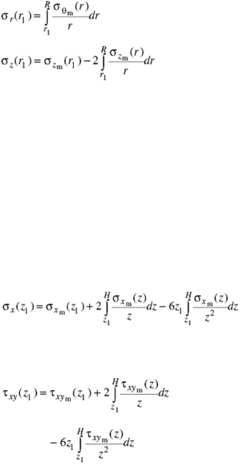
Solid Cylinder Bar with Rotationally Symmetric Stresses. It was presumed that the residual stress distribution
had both rotational and longitudinal symmetry, except near the ends where measurements were avoided.
Stresses were therefore functions of the radius, r, and did not depend on the angle, θ, measured around the
cylinder, nor the distance, z, taken parallel to the axis. With repeated removal of thin concentric shells, the
stresses on the exposed surface in depth were obtainable. The circumferential and longitudinal measures of
stress, σ
θm
(r) and σ
zm
(r), respectively, were then used to calculate the original stresses, σ
θ
(r) and σ
z
(r), as well
as the radial stress, σ
r
(r).
The theory of elasticity provides nine partial differential equations—the three equations of equilibrium and the
six equations of compatibility. Unique solutions are possible, depending on boundary conditions. For the case
considered, the nine equations give the following working formulas:
(Eq 16)
(Eq 17)
σ
θ
(r
1
) = σ
θm
(r
1
) + σ
r
(r
1
)
(Eq 18)
where r is the original radius, and r
1
is the radius at the depth of interest.
Solid Cylinder Bar without Rotationally Symmetric Stresses. Stresses were again assumed independent of z but
allowed to vary in the circumferential, θ, direction. Complex variable methods gave general solutions for
stresses in the radial, σ
r
(r
1
,θ) circumferential, σ
θ
(r
1
,θ); and axial, σ
z
(r
1
,θ), directions as well as the shear stress,
τ
rθ
(r
1
,θ). Details of the equations used may be found in the references (Ref 6 or 8).
Hollow Cylinder Bar with Rotationally Symmetric Stresses. With the inside radius included in the equations
used to calculate σ
r
(r
1
), σ
z
(r
1
), and σ
θ
(r
1
), the general solutions for these stresses are developed (Ref 6, 8).
Flat Plate with Biaxial Stresses. It was assumed that the residual stresses in a flat plate of uniform thickness
depended only on the distance from one of the flat surfaces of the plate, except, of course, near the edges. It was
also assumed that the principal stresses are σ
x
and σ
y
, lying in the plane of the flat surfaces, and that the stress
normal to the flat surfaces, σ
z
, was zero at all points sufficiently distant from the edges.
From the assumptions and conditions of equilibrium, the true stresses σ
x
(z
1
) at depth z
1
could be expressed in
terms of the measured stress σ
xm
(z
1
) by the relation:
(Eq 19)
where H = original thickness of the plate and z
1
= distance from lower surface to uncovered depth of interest.
A similar expression holds for the y direction. Equation 19 holds, even if σ
x
and σ
y
are not principal stresses, but
in this case a shear stress also exists, expressed by:
(Eq 20)
τ
xym
(z) is determined from:
σ
αm
(z
1
) = σ
xm
(z
1
) cos
2
α + σ
ym
(z
1
) sin
2
α
+ 2τ
xym
(z
1
) sin α cos α
(Eq 21)
where α is the acute angle that the measured stress σ
αm
(z
1
) makes with the x axis. When measurements are
taken 45° apart, τ
xym
(z
1
) becomes:
τ
xym
(z
1
) = σ
45 deg
(z
1
- (σ
xm
(z
1
)
+ σ
ym
(z
1
))
(Eq 22)
meaning that three x-ray stress measurements are required after each layer is removed.
Johanssen (Ref 32) proposed a procedure for the determination of the three-dimensional residual stress field in
thick plate (plate weldments) components using XRD techniques to measure the strains on the surfaces of the
plate and plate sections and on removal of layers of surfaces. The procedure included the measurement of the
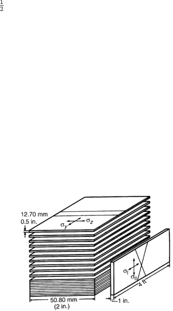
biaxial stress field existing on the top surface of the component (Fig. 6), assuming that the stress perpendicular
to the surface is zero. Material was removed from this surface by, for example, milling and electropolishing or
by electropolishing alone (see the section “Sectioning and Material Removal Methods”), and the biaxial
stresses were remeasured at the new depth. Each time material was removed, the forces that the removed layer
exerted on the remaining component had to be accounted for, and the subsequent measurements required
correction for this change in the stress field. Johanssen based his method on the following assumptions:
• When a layer of material is removed, the resulting changes in the stress condition will be linear elastic;
that is, Hooke's law is applicable.
• The residual stress distribution is constant in the z-direction, except at the surface, and σ
z
is a principal
stress in the z-direction (Fig. 6).
• On material removal, it is assumed that the strain, ε
z
, remains unchanged. Together with the previous
assumption, this implies that the change in stresses can be treated as a plane problem.
• It is assumed that the stresses are symmetrical with respect to the y-z plane. This assumption is,
however, not necessary. The procedure can be developed to include asymmetrical stress states.
Fig. 6 A 2 ft by 2 ft by 4 ft weldment showing the layers proposed by Johanssen (Ref 32) where the
thickness (T) of the layers are 12.70 mm (0.5 in.) and σ
I
= σ
y
, σ
II
= σ
x
, and σ
III
= σ
z
Johanssen's (Ref 32) justification for his procedure to measure the three-dimensional stress field in the
weldment shown in Fig. 6 is as follows.
Johanssen showed that the change in stresses resulting from the removal of material can be determined by
Δσ(x) and ν(x) shown in Fig. 7. These were to be measured at a number of positions x
i
, i = 1, …, N, on the
lower side of the plate. Δσ
x
(x) and ν(x) are the differences between the stress and deformation measured prior to
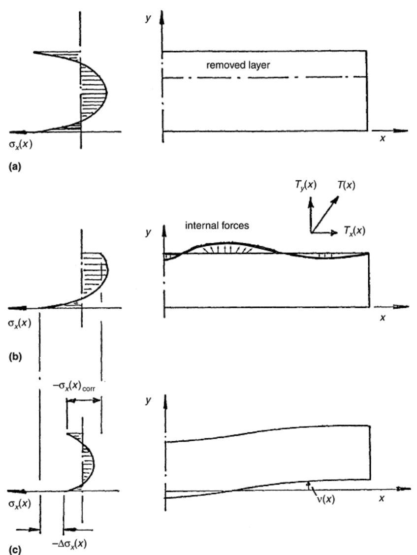
and following the removal of material. Changes in the internal stress conditions are thus calculated directly and
need not be calculated as accumulated stress changes resulting from several layers of material being removed.
The development of equations for the stress reconstruction may be found in Ref 32.
Fig. 7 Residual stress distributions, forces, and distortion of a plate before and after layer removal. (a)
Residual stress distribution in the x-direction in the center of the plate in the x-z plane. (b) Same as (a)
after removal of a layer with the forces T
i
(j) caused by the residual stresses tending to distort the plate.
(c) Same as (b) with the distortion displacement shown (Ref 32)
Pickel (Ref 40) described a method for analytical solution of problems with similar boundary conditions to
Johanssen's, using infinite, related series, but in this instance, an approximate method was used with trial
solutions that were more convenient and numerically more stable than those used by Johanssen.
Sikarskie (Ref 41) proposed a stress reconstruction procedure (series method) when thin layers were removed
from the surface of a component. He described procedures applicable to flat plates and solid cylinders. The
procedure works well for shallow depths (a few percent of specimen diameter or thickness) or in instances
where the stress gradient over the total depth removed does not change too rapidly and is of essentially one
sign. The practicality of this method depends on the fit of the measured stresses in depth by a Taylor's series
referred to the surface values of stress and successive derivatives at the surface. When the method is applicable,
very convenient relations are obtained, which describe the stress correction in terms of the influencing factors;
for example, layer depth, stress magnitude, stress gradient, and specimen size. Judgment is necessary, however,
in using the series approximation, which does not arise when using the exact equations of the previous sections.
The method is summarized for two of the previous cases as follows.
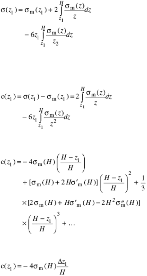
Flat Plate. (See the previous discussion “Flat Plate, Biaxial Stress” for the Moore and Evans procedures.) A
generalized solution is written:
(Eq 23)
The subscripts x, y, or xy have been dropped, because the form of Eq 19 and 20 are exactly the same. σ(z
1
)
represents the true stress in any direction at depth, z
1
, before a layer was removed, and σ
m
(z
1
) represents the
measured value at that depth.
The correction in stress, c(z
1
), at z
1
is the difference between the true and measured values, given by:
(Eq 24)
The integrands are then expanded in a Taylor's series referred to the surface values, after which the integration
is performed term by term. The final form for the correction is:
(Eq 25)
where σ
m
(H), σ′
m
(H) are true surface stress and successive derivatives with respect to z at the surface.
For shallow depths only, the first terms of the series may be used and:
(Eq 26)
where Δz
1
= H - z
1
. This correction is seen to be approximately proportional to the magnitude of the surface
stress and thickness of the removed layer (Fig. 8). It is inversely proportional to the specimen thickness.
