ASM Metals HandBook Vol. 8 - Mechanical Testing and Evaluation
Подождите немного. Документ загружается.


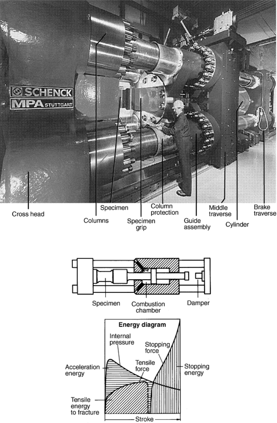
Fig. 14 High-loading-rate tensile testing machine (12 MN capacity)
Fig. 15 Test configuration and energy diagram for high-loading-rate propellant-driven tensile testing
machines

Tests were carried out on unwelded and welded wide plate specimens (e.g., 960 mm, or 37.8 in., long; 500 mm,
or 19.7 in., wide; and 40 mm, or 1.6 in., thick) with and without different flaw positions as well as for pipe
sections (e.g., 406 mm, or 16 in., outer diameter and 12.5 mm, or 0.5 in., wall thickness; 168 mm, or 6.6 in.,
outer diameter and 4.5 mm, or 0.18 in., wall thickness; or 220 mm, or 8.6 in., outer diameter and 16 mm, or 0.6
in., wall thickness) with and without circumferential cracks. Austenitic and ferritic materials were investigated
(Ref 53, 54).
Cyclic/Repeated Loading. Different types of test equipment were used for cyclic/repeated external bending
moment loading on straight pipes and elbows:
• Bending device for resonance excitation in which fast-alternating external bending loads with high
acceleration can be generated (Ref 55) (Fig. 16).
• 12 MN · m bending device for low-cycle, load-controlled, bending loads for pipe dimensions up to 800
mm (31.5 in.) nominal diameter and 50 mm (2 in.) wall thickness (Ref 55).
• The deformation and failure behavior of thick-walled elbows made of austenitic material was
investigated in Ref 56. The dimensions of the elbow were 108 mm (4.25 in.) outer diameter and 12 mm
(0.47 in.) wall thickness. The bend angles were 60° and 90°.
Numerous piping experiments have also been performed at the German Heissdampfreaktor (HDR) Test Facility
(Ref 57). It was built in the period 1965 to 1969 for a prototype superheated steam reactor, but was shut down
in 1971 after only 2000 h of operation. After extensive decommissioning and conversion work, it was used
from 1974 until 1991 by the HDR Safety Project of the Kernforschungszentrum Karlsruhe to perform
vibrational/seismic, thermal hydraulic, blowdown, and other experiments related to the safety and design of
nuclear power plants. The load-bearing capacity margins of a piping system with different pipe dimensions and
degraded pipe sections under operating conditions were demonstrated for earthquake-type loads (Ref 58).
Experiments were also performed to demonstrate the behavior of a full-size feedwater piping system under
operational conditions (Ref 59) (Fig. 17).
Fig. 16 Resonance bending device. Dimensions are in millimeters.

Fig. 17 Reactor pressure vessel (RPV) piping system with degraded elbow
High-Temperature Loading. A pipe component test (700 mm, or 27.6 in., inside diameter and 47 mm, or 1.9 in.,
wall thickness) to verify the failure behavior postulated from small-specimen tests was carried out to simulate
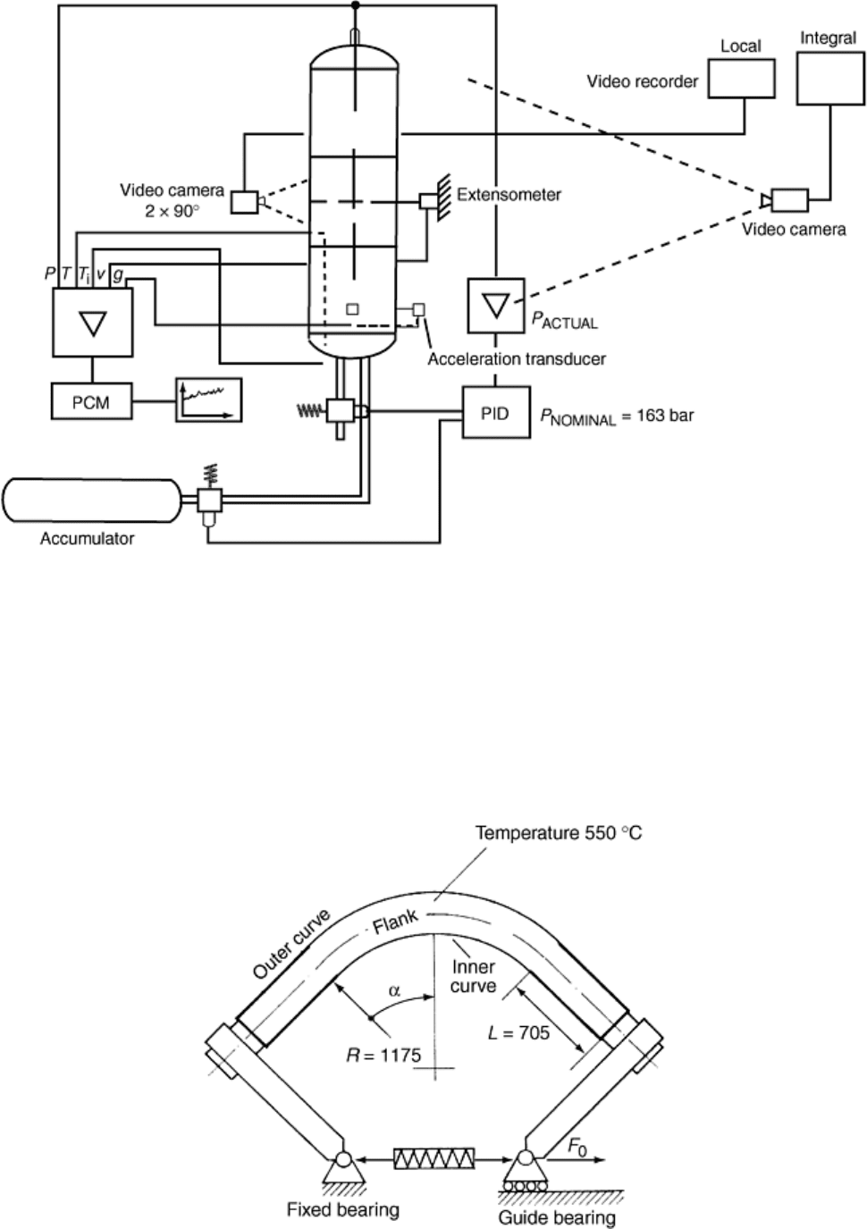
specific accident conditions (Ref 60). Under constant internal pressure of 16.3 MPa (2.4 ksi) using air as
pressurizing medium, the pipe was heated up to about 700 °C (1300 °F) to determine the time to failure (Fig.
18).

Fig. 18 Test assembly and measurement data collection for testing pipe components under high-
temperature loading. PCM, pulse code modular (data acquisition unit); PID, pressure controller; p,
pressure; T, outside temperature; v, displacement; g, acceleration; T
i
, inside temperature
Creep damage had been observed in elbows (235 mm, or 9.3 in., outer diameter and 25 and 30 mm, or 1 and 1.2
in., wall thickness) in steam piping of fossil-fired power plants. It was assumed that the reasons for this damage
were additional forces and moments and also geometrical effects (Ref 61). For that reason, the creep damage
and failure behavior of a low-alloy 0.6% Mo steel elbow and a high-alloy 12% Cr steel elbow under internal
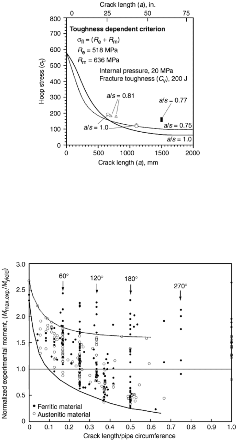
pressure and a superimposed static bending moment at 550 °C (1000 °F) were investigated in experiments. The
test configuration is shown in Fig. 19.
Fig. 19 Test configuration for evaluating long-term creep failure behavior of pipe elbows. F
0
, external
static force; R, pipe elbow radius; L, length of the straight ends of the elbow

During all the tests, the variation with time of internal pressure, bending moment, crack opening displacement,
crack extension, bending deflection (load-line displacement, strain measurement), and ovalization should be
measured to monitor the loading conditions as well as the deformation behavior. Based on the results of the
measurements, a comparison between experimental and numerical calculated data is possible. That is why a
detailed plan of instrumentation before the tests was developed. In all of the tests mentioned above, the
requirements on data acquisition systems and measuring parameters throughout the tests required high-
performance data acquisition units.
Some of the specific and interesting test results achieved by running experiments with the above-mentioned test
facilities are discussed in the following sections.
Examples of Test Results
Longitudinally Cracked Components. Figure 20 is an example of catastrophic failure from a full-scale internal
pressure test (using air as the pressurizing medium) of a feedwater vessel. For crack initiation, a brittle disk was
welded in the feedwater tank with a longitudinal notch to initiate the crack (Ref 45). The vessel was completely
destroyed because of the compressibility of air. This test shows the influence of stored energy on the failure
behavior.
Fig. 20 Catastrophic failure at internal pressure of a feedwater tank
Table 2 summarizes test results for straight pipe with longitudinal defects. The pipes are made of ferritic
material having different toughness values, and the failure loads are calculated on the safe side by means of the
toughness-dependent approximation technique (Ref 14, 45) (Fig. 21).

Table 2 Test results for longitudinally cracked piping under internal pressure loading
Crack length Crack depth Temperature Burst
pressure
Stress at
failure
Hoop stress Test No.
mm in. mm in.
a/t
°C °F MPa ksi MPa ksi MPa ksi
Normalized
crack
opening area
Remarks
Pipe with C
v
> 150 J
BVZ010 650 25.6 … … 1.00 20 68 23.8 3.5 187 27.1 178 25.8 0.02
…
BVZ011 1102 43.4 … … 1.00 20 68 14.8 2.1 117 17.0 111 16.0 0.05
…
BVZ012 1105 43.5 … … 1.00 20 68 14.4 2.1 113 16.4 108 15.6 0.16
…
BVZ022 782 30.8 38.3 1.5 0.81 305 581 21.9 3.2 173 25.1 164 23.7 0.04
Leakage
BVZ030 1500 59.1 36.2 1.4 0.77 300 572 19.5 2.8 155 22.5 146 21.1 >2
Large break
BVZ080 1500 59.1 36.2 1.4 0.77 17 63 20.4 3.0 164 23.8 152 22.1 0.12
Leakage
BVZ070 700 27.6 38.2 1.5 0.81 265 509 22.4 3.2 177 25.7 167 24.3 0.01
Leakage
BVZ060 1500 59.1 36.0 1.4 0.76 305 581 18.0 2.6 143 20.7 135 19.5 0.16
Large break
Pipe with C
v
= 50 J
BVS010 800 31.5 … … 1.00 155 311 17.5 2.5 137 19.9 131 19.0 0.1
…
BVS020 709 27.9 37.3 1.5 0.79 320 608 14.8 2.1 117 17.0 111 16.0 0.02
Limited break
BVS030 1100 43.3 35.0 1.4 0.74 305 581 13.1 1.9 103 14.9 98 14.2 0.11
Large break
BVS042 709 27.9 38.3 1.5 0.81 245 473 16.8 2.4 132 19.1 126 18.2 >2 Large break
(a) Pipe outer diameter: 800 mm (31.5 in.), wall thickness: 47.2 mm (1.86 in.)

Fig. 21 Test results for longitudinally cracked straight pipes (outer diameter, 800 mm, or 31.5 in.; wall
thickness, 47.2 mm, or 1.86 in.) under internal pressure (burst test). R
e
, yield strength; R
m
, tensile
strength; a, crack depth; s, wall thickness
Tests were also performed on large-diameter pipe elbows and pipe T-joints under internal pressure and
superimposed quasi-static external bending moment loading.
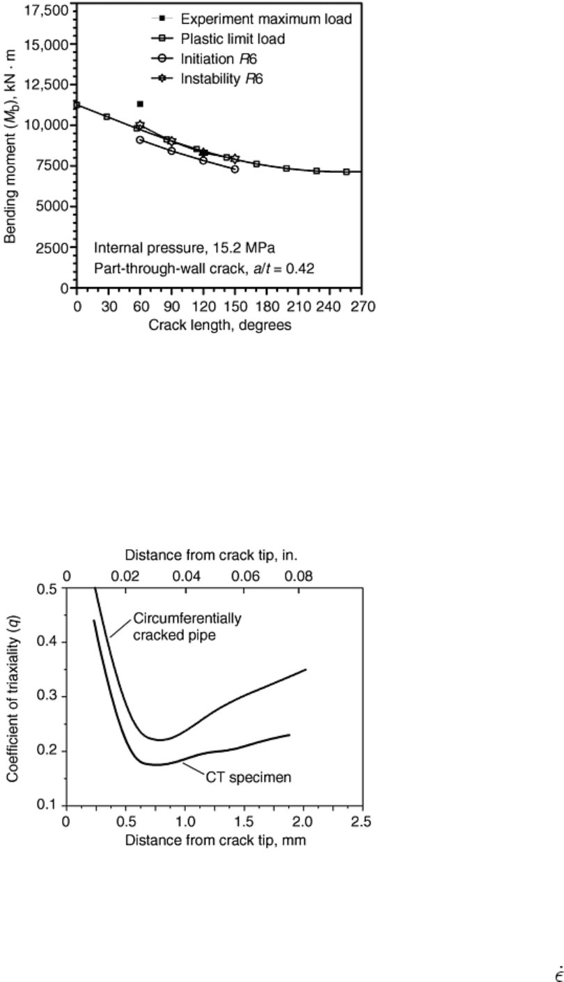
Circumferentially Cracked Components (Straight Pipes). The experimental results of more than 330 tests with
circumferentially cracked pipes with both austenitic and ferritic material are shown in Fig. 22 as normalized
experimental moment versus the normalized crack length. It has to be supposed by the test facilities that in the
cracked cross section of the pipes the loading condition is constant, especially in moment loading (Fig. 23).
Fig. 22 Results of experimental moment versus crack length for tests for circumferentially cracked pipes
(333 full-scale pipe tests)

Fig. 23 Constant-moment loading for straight pipes
With the engineering methods (plastic limit load calculation) used and an appropriate flow stress, the
experimental maximum moment can be estimated with some accuracy if the expression to calculate the flow
stress is adjusted to experimental results. This is demonstrated in Fig. 24 using plastic limit load calculations
based on different flow stress assumptions in comparison with experimental results. More precise calculations
of the failure course (for example, initiation and instability loads) are possible with the fracture mechanics
approximation methods like the two criteria approach or the R-curve method. The results based on J
i
demonstrate the transferability of this initiation value to components. The greater differences in the calculated
results of the failure load depend on the J
R
-curve that could be used only if the triaxiality of the stress state in
the ligament in front of the crack tip is comparable to the specimen from which the J
R
-curve is evaluated and
the component. This is shown in Fig. 25 and 26.

Fig. 24 Comparison of experimental and calculated loads versus the crack length for pipe with outer
diameter of 331 mm (13 in.) and wall thickness of 32 mm (1.3 in.)
Fig. 25 Comparison of experimental and calculated loads versus the crack length for pipe with outer
diameter 800 mm (31.5 in.), wall thickness 50 mm (2 in.); ferritic material, through-wall crack, σ
fl
= (R
p0.2
+ R
m
)/2.4

Fig. 26 Comparison of experimental and calculated loads versus the crack length for pipe with outer
diameter 800 mm (31.5 in.), wall thickness 50 mm (2 in.); ferritic material, part-through-wall crack, σ
fl
=
(R
p0.2
+ R
m
)/2.4
Figure 27 shows the distribution of the coefficient of triaxiality q across the ligament of a fracture mechanics
compact tension (CT) specimen compared with q values calculated for a circumferentially cracked pipe. This
comparison shows that the transferability of the crack resistance curve determined on a CT specimen to the pipe
with circumferential crack is not direct. However, because of the much steeper q gradients and the higher q
values in the investigated pipes, it is not surprising to be on the safe side when calculating the failure load of the
pipes. In all cases, however, this has to be proven.
Fig. 27 Distribution of q value across the ligament at the plane of symmetry of a compact tension (CT)
specimen and a circumferentially cracked pipe
Based on an extensive program of high-speed tensile tests with large-diameter pipes (406 mm, or 16 in., outer
diameter; 12.5 mm, or 0.5 in., wall thickness; material with low upper-shelf Charpy impact energy), no
indications of unfavorable material behavior resulting from the dynamic loading conditions up to transients of
= 6/s (Fig. 28, 29) were found. The tests show increasing loadability with increasing strain rate.
