ASM Metals HandBook Vol. 8 - Mechanical Testing and Evaluation
Подождите немного. Документ загружается.


Values of K
Q
that pass all validity requirements are labeled as valid K
Ic
and are reported as such. The ASTM E
399 standard lists all of the information required for the test report.
Rapid-Load K
Ic
(t) Test
A value of fracture toughness labeled K
Ic
(t) can be determined for a rapid-load test. Details of this method are
given in a special annex to ASTM E 399 (Ref 6). For the static loading rate K
Ic
value, the maximum loading
rate is 2.75 MPA /s. Anything faster than that is labeled as a rapid-load fracture toughness. The
specimens, apparatus, and procedure are much the same as for the regular K
Ic
test. Special instructions are given
to ensure that the instrumentation can handle the rapidly changing signals. The interpretation of results must be
based on a dynamic value of the yield stress, σ
YD
. An equation for σ
YD
is given in the Annex to ASTM E 399.
Results are reported as K
Ic
(t), where the loading time of the test, t, is written in parentheses after the measured
toughness value.
K-R Curve Test (ASTM E 561)
Ductile fracture toughness behavior is measured by a crack growth resistance curve, or R-curve, which is
defined as “a plot of crack-extension resistance as a function of slow-stable crack extension” (Ref 1). Although
many ductile fracture processes can be measured as a single-point, such as with K
Ic
, the R-curve is a more
complete description of the fracture toughness. When the R-curve increases significantly with increased
loading, a single-point measurement is even less descriptive of the actual fracture toughness. Steeply rising R-
curves occur in many metallic materials but especially in thin plate or sheet materials. The steeply rising R-
curve makes the single-point definition of fracture toughness more size-dependent and geometry-dependent and
does not lend itself to correct structural evaluation.
The K-R curve is a good method for fracture toughness characterization in cases where the R curve is steeply
rising but the fracture behavior occurs under predominantly linear-elastic loading conditions. The K-R curve
procedure is given by ASTM E 561 (Ref 7). The objective of the method is to develop a plot of K, the
resistance parameter, versus effective crack extension, Δa
e
. The method allows three different test specimens,
the compact, C(T), the center-cracked tension panel, M(T), and the crack-line-wedge-loaded specimen, C(W).
The compact specimen is shown in Fig. 2(b). The center-cracked tension panel and the crack-line-wedge-loaded
specimens are shown in Fig. 6(a) and (b), respectively. The first two specimens use a conventional loading
machine with fixtures that are specified in the test method. The C(W) specimen is wedge loaded to provide a
stiff, displacement-controlled loading system (Fig. 6b). This can prevent rapid, unstable failure of the specimen
under conditions where the R-curve toughness is low so that the R curve can be measured to larger values of
Δa
e
. All specimens must be precracked in fatigue.
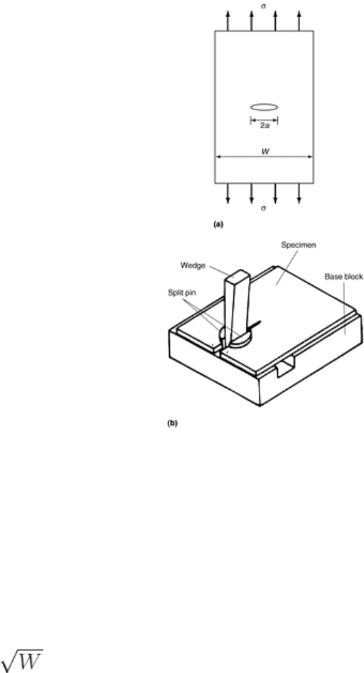
Fig. 6 Specimens for the K-R curve test (ASTM E 561). (a) Center-cracked tension specimen, M(T). (b)
Crack-line-wedge-loaded compact specimen, C(W), in loading fixture
The instrumentation required on the specimens is similar to that for the K
Ic
test, except for the case of the C(W)
specimen. The basic test result is a plot of load versus a displacement measured across the specimen mouth.
From this, an effective crack length is determined from secant slopes on the load-versus-displacement record
(Fig. 7). An effective crack extension is the difference between the original and effective crack lengths.
Effective crack length is determined from the slope of the secant offset using the appropriate compliance
function, which relates this slope to crack length. The K is determined as a function of the applied load, P, and
corresponding effective crack length. This is given by:
K = P f(a
c
/ W) /
(Eq 4)
The resulting plot of K versus effective crack length is the desired K-R curve fracture toughness. The result is
subjected to a validity requirement that limits the amount of plasticity. For the C(T) and C(W) specimens
b = (W - a) ≥ (4/π)/(K
max
σ
ys
)
2
(Eq 5)
where b is the uncracked ligament length, σ
ys
is the 0.2% offset yield strength, and K
max
is the maximum level
of K reached in the test. For the M(T) specimen, the net section stress based on the physical crack size must be
less than the yield strength.
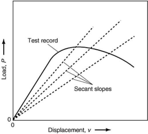
Fig. 7 Secant measurement of effective crack length
For the C(W) specimen, a load is not measured. The data collected are a series of displacement values taken at
two different points along the crack line, one near the crack mouth and one nearer the crack tip. From the two
different displacement values, an effective crack length can be determined from the ratio of the two
displacement values and from calibration values given in ASTM E 561. From the crack length and
displacement a K value can be determined and the K-R curve constructed. The toughness result is then a curve
of K versus Δa
e
, somewhat similar to the one in Fig. 1. The K-R curve fracture toughness is a function of the
material thickness; all results are given for a specified thickness. There is no validity requirement relating to a
thickness level as with the K
Ic
standard.
Crack Arrest, (K
Ia
) Test (ASTM E 1221)
This procedure allows a toughness value to be determined based on the arrest of a rapidly growing crack. The
specimen and procedure are somewhat different from those for the previously discussed toughness test
methods, which determine initiation toughness values only. The specimen for crack arrest testing is called the
compact crack-arrest specimen (Fig. 8). It is similar to the crack-line-wedge-loaded specimen, C(W), of the K-R
curve method and requires wedge loading in order to provide a very stiff loading system to arrest the crack. The
specimen also requires side grooves—machined notches on the specimen planar face (Fig. 8)—to aid in getting
a straight-running crack during the test. The notch preparation is different from that used in the other standards
in that the specimen has a notch with no precrack. A brittle weld bead is placed at the notch tip to start the
running crack. The running crack advances rapidly into the test material and must be arrested by the test
material to produce a K
Ia
result. The only instrumentation on the specimen is a displacement gage. A load cell is
placed on the loading wedge, but it does measure the load on the specimen. The displacements at the beginning
of the unstable crack extension and at the crack arrest position are measured and converted to K values. To
eliminate effects of nonlinear deformation, which cannot be directly measured with only a displacement gage, a
series of loads and unloads are conducted on the specimen until the unstable cracking occurs.
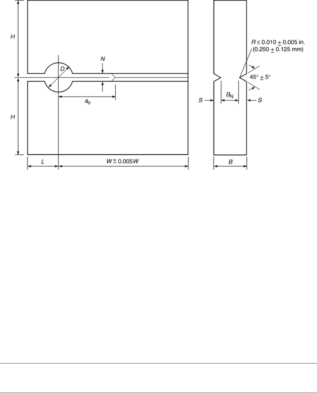
Fig. 8 Crack-line-wedge-loaded compact crack-arrest specimen
The value of K
Ia
is determined from a displacement value and the crack length at the arrest point. Validity is
determined from the size criterion:
W - a ≥ 1.25 (K/σ
YD
)
2
(Eq 6)
where σ
YD
is a dynamic yield strength. To complete a successful K
Ia
test, careful attention must be paid to the
instructions in ASTM E 1221 (Ref 8).
References cited in this section
1. “Standard Terminology Relating to Fracture Testing,” E 616, Annual Book of ASTM Standards, Vol
3.01, ASTM
6. “Standard Method for Plane-Strain Fracture Toughness of Metallic Materials,” E 399, Annual Book of
ASTM Standards, Vol 3.01, ASTM
7. “Standard Practice for R-Curve Determination,” E 561, Annual Book of ASTM Standards, Vol 3.01,
ASTM
8. “Standard Method for Determining Plane-Strain Crack Arrest Toughness, K
Ia
, of Ferritic Steels,” E
1221, Annual Book of ASTM Standards, Vol 3.01, ASTM
Fracture Toughness Testing
John D. Landes, University of Tennessee, Knoxville
Nonlinear Fracture Toughness Testing
Linear-elastic parameters are used to measure fracture toughness for relatively low toughness materials, which
fracture under or near the linear-loading portion of the test. For many materials used in structures, it is desirable
to have high toughness, a value at least high enough so that the structure would not reach fracture toughness
before significant yielding occurs. For these materials, it is necessary to use the nonlinear fracture parameters to
measure fracture toughness properties. The two leading nonlinear fracture parameters are J and δ.
For many of the nonlinear fracture toughness measurements, the fracture mode is a ductile one. In this case the
fracture toughness is measured by an R-curve, that is, a plot of the fracture-characterizing parameter as a
function of the ductile crack advance. The evaluation of the R-curve toughness requires three measurements
during the test: load, displacement, and crack length. The load and displacement are standard measurements.
The crack length requires a special monitoring system. In the standards, the crack length has been measured
visually on the fracture surface and by an elastic unloading compliance method that uses the elastic properties
of the specimen geometry to evaluate crack length. Methods that have also been used are an electrical potential
drop method and a key curve, or normalization, method. The electrical potential method uses the electrical
resistance of the material to evaluate crack length. The method of normalization uses the plastic deformation
properties of the material to evaluate crack length.
The visual method was the first and longest used of the methods. It has a disadvantage in that it requires a
number of specimens to evaluate one R-curve. Each specimen generates only one point on the R-curve. It is
often called the multiple-specimen method. The other methods require only one specimen to generate an R-
curve and are often called single-specimen methods. The elastic unloading compliance method is the most often
used of the single-specimen methods and is used in many of the standards to measure fracture toughness during
nonlinear loading. It cannot be used under rapid loading conditions or for materials that do not have a linear-
elastic loading character. This would include polymer materials. The electrical potential drop method requires a
material that has a measurable electrical resistance. It is mostly used for metallic materials. In the past it has
been in some standard test methods, but presently it is withdrawn from all existing standards because it has not
always given accurate crack length measurement during a fracture toughness test. The method of normalization
has not been standardized. It is advantageous in that it can be used for any material that generates nonlinear
loading that is similar to plastic deformation in metals. It can be used to measure crack length both for polymers
and for rapid loading test conditions.
J
Ic
Testing (ASTM E 813)
The first standard test developed using the J parameter is the J
Ic
test, originally standardized as ASTM E 813
(Ref 9). (Changes to this standard will be discussed later.) In this test an R-curve is developed using J versus Δa
pairs. A point near the beginning of the R-curve is defined as J
Ic
, “a value of J near the onset of stable crack
extension” (Ref 9). The specimens for the J
Ic
test are the bend, SE(B), and compact, C(T). These are similar to
the ones used for K
Ic
testing (Fig. 2a and b); however, the compact specimen for J testing allows for a load line
displacement measurement in the line of the applied loads. Therefore, a cutout is machined in the front of the
specimen to accommodate the placement of a clip gage on the load line (Fig. 9). Also, side grooving is
recommended on this specimen to assist in maintaining a straight crack front during the stable crack growth.
The loading fixtures required are the bend fixture for the bend specimen (Fig. 3a) and the pin and clevis for the
compact specimen (Fig. 3b). As with the K
Ic
test, the clevis has a loading flat at the bottom of the pinhole,
which is essential for free rotation of the specimen. The instrumentation required is the load cell and a
displacement measuring clip gage. The clip gage for the J
Ic
test requires more resolution than that for the K
Ic
test if a single-specimen test method is used. For the bend specimen, a loadline clip gage is needed to measure
J. Additionally, a second clip gage can be used over the crack mouth if a single-specimen method is used.
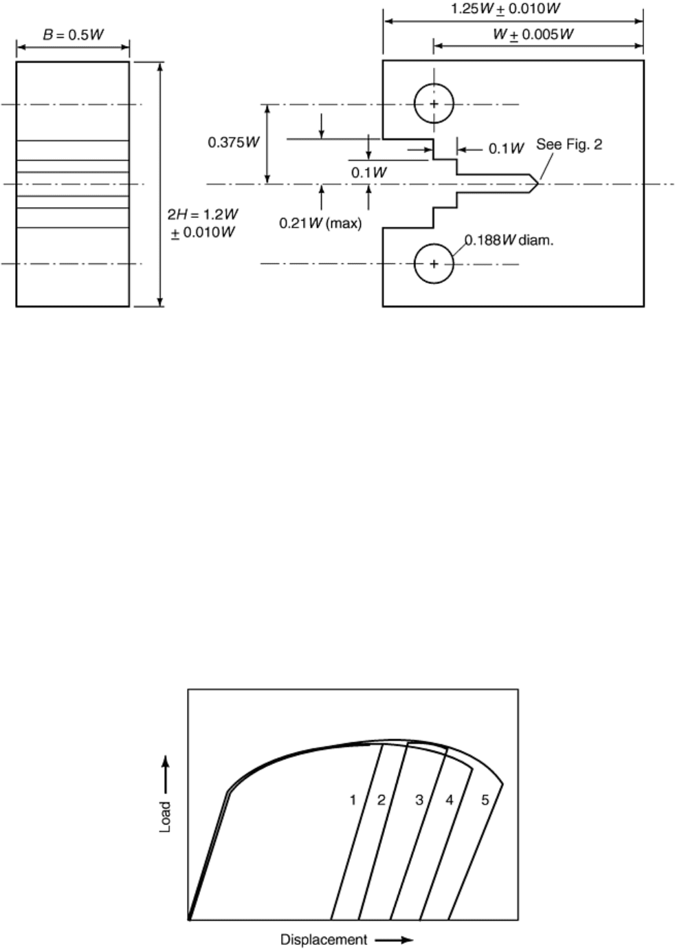
Fig. 9 J
Ic
compact specimen with load line cutout
J
Ic
Test Procedures. The basic output of the test is a plot of J versus physical crack extension (Δa). (Unlike the
K-R curve method, which uses effective crack extension, the J
Ic
test uses physical crack extension.) To obtain
the required J versus Δa data, measurements of load, displacement, and physical crack length are required
during the test. Two techniques are used to develop these data. The first is the multiple-specimen test method,
in which each specimen develops a single value of J and Δa, but no special crack monitoring equipment is
needed during the test. Crack extension is measured on the fracture surface at the conclusion of the test.
However, for this technique a number of specimens (usually five or more) are required to develop the plot of J
versus Δa from which the J
Ic
is evaluated. The other test method is the elastic unloading compliance method, a
single-specimen test from which all of the J and Δa values needed for the result are developed from one test
specimen.
The test procedure depends on the method of crack length monitoring. For the multiple-specimen test, five or
more identical specimens are loaded to prescribed displacement values that are expected to give some physical
crack extension without complete separation of the specimen. This results in a number of individual load-
versus-displacement records as shown in Fig. 10. When the prescribed displacement is reached, the specimen is
unloaded, and the crack tip is marked by a procedure called heat tinting. Heat tinting consists of marking the
physical crack extension by heating the specimen until oxidation occurs on the crack. The specimen is then
broken open, and the crack extension is measured on the fracture surface.
Fig. 10 Load versus displacement for multiple-specimen tests
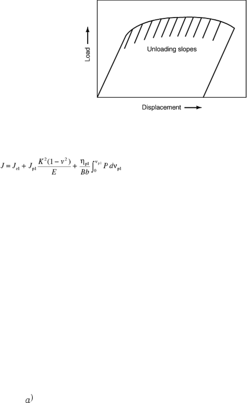
The single-specimen method using elastic compliance is initially loaded in the same way; however, during the
test, partial unloadings are taken to develop elastic slopes from which crack length can be evaluated using
compliance relationships (Fig. 11). The compliance relationships are given in ASTM E 813 (Ref 9).
Fig. 11 Load versus displacement with unloading slopes
Data Evaluation. From these test results, J is evaluated from the load-versus-loadline displacement record. The
J is calculated from a linear combination of an elastic term and a plastic term given as:
(Eq 7)
where K is the stress-intensity factor, E is elastic modulus, ν is Poisson's ratio, P is load, ν
pl
is plastic
displacement, B is specimen thickness, b is specimen uncracked ligament (W - a, where W is specimen width)
and η
pl
is a coefficient that has values of η
pl
= 2 for the SE(B) specimen of Fig. 2(a) and η
pl
= 2 + 0.522b/W for
the compact specimen of Fig. 9.
The crack length is used to determine Δa = a - a
0
, where a
0
is the original crack length at the beginning of the
test. For the multiple-specimen method, all Δa values are determined from measurements taken from the
fracture surface of the test specimen. For some metals, heat tinting does not oxidize the crack surfaces, and
another method of marking the crack extension, for example posttest fatiguing, can be used. The specimen is
broken in two after the heat-tint procedure, usually at a low temperature to induce brittle fracture for easy
reading of the ductile crack extension and to otherwise minimize plastic deformation during this procedure.
Typically, this is done by cooling the specimen to the temperature of liquid nitrogen before breaking it in two.
Crack lengths a
0
and a
f
, original and final, are measured on the fracture surface. A nine-point measurement and
averaging method is used because the crack front is usually neither straight or regular. This procedure is
described in ASTM E 813 (Ref 9). For the single-specimen methods for which crack length monitoring systems
are used, the crack length is evaluated at prescribed points during the test. In the elastic unloading compliance
method, a crack length can be determined at each unload. Typically, about 20 of 50 unloading data pairs, P, ν,
and a are evaluated for each test. For single-specimen tests, a physical measurement of the final crack length is
made at the end of the test using the same procedure that is followed for the multiple-specimen test, so that this
measured crack length can be compared with the final crack length evaluated by the crack monitoring system.
The J versus Δa results form a part of the J-R curve and are the basic data of the J
Ic
method. The objective is to
get J versus Δa values in a certain restricted range. These data are then subjected to a prescribed evaluation
scheme to choose a point on the J-R curve that is near the initiation of stable cracking. The method for
developing the J
Ic
is somewhat complicated, and the details are given in ASTM E 813 (Ref 9). Basically, the J
versus Δa pairs are evaluated to see which fall in a prescribed range. The pairs falling in the correct range are
fitted with a power-law equation:
J = C
1
(Δ
(Eq 8)
where C
1
and C
2
are constants. A construction line is drawn, and the intersection of this with the fitted line, Eq
8, is the evaluation point for a candidate J
Ic
value. This candidate value is labeled J
Q
. A schematic of the
process of J
Ic
evaluation is shown in Fig. 12.
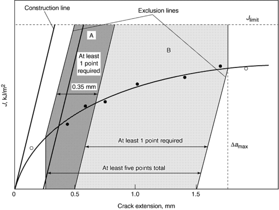
Fig. 12 J
Ic
evaluation scheme
The candidate J
Q
value is subjected to qualification criteria to see if it constitutes an acceptable value. The basic
one is to guarantee a sufficient specimen size:
b, B ≥ 25(J
Q
/ σ
Y
)
(Eq 9)
where σ
Y
is an effective yield strength and
σ
Y
= (σ
ys
+ σ
uts
)/2
(Eq 10)
where σ
ys
and σ
uts
are the yield strength and ultimate tensile strength, respectively.
If the qualification requirements are met, the J
Q
is J
Ic
and the results are reported following the prescribed
format in ASTM E 813 (Ref 9).
J-R Curve Evaluation (ASTM E 1152)
A more complete evaluation of fracture toughness for ductile fracture based on J is the J-R curve. The test
procedure was originally standardized as ASTM E 1152 (Ref 10). This standard uses the same specimens,
instrumentation, and test procedures as the J
Ic
test. The J-R curve test cannot be conducted with the multiple-
specimen test procedure; it must use a single-specimen procedure. The purpose of the J-R curve is to develop
points of J versus Δa; these comprise the fracture toughness evaluation. A single value of J is not specifically
measured as it is for the J
Ic
procedure. The single-specimen method used is again primarily the elastic
unloading compliance method. Equation 7 is the basic J formula for the case of a nongrowing crack. It is based
on a K equivalence for the elastic component of J and an area term for the plastic component of J. Alternate J
formulas are given in ASTM E 1152 (Ref 10) for the growing crack. Qualification criteria are also given in the
standard (Ref 10). The J
Ic
and J-R curve methods are very similar; hence the two have recently been combined
into one standard, ASTM E 1820 (Ref 11). The individual standard ASTM E 813 and E 1152 were withdrawn
from the Annual Book of ASTM Standards beginning in 1998.
Crack Tip Opening Displacement (CTOD) Test (ASTM E 1290)
The crack tip opening displacement method of fracture toughness measurement was the first one that used a
nonlinear fracture parameter to evaluate toughness (Ref 5). The first CTOD standard was written by the British
Standards Institution (Ref 12). Subsequently, ASTM E 1290 was written as the U.S. version of this test method
(Ref 13). The basic idea of the test method is to evaluate a fracture toughness point for brittle fracture or to
evaluate a safe point for the case of ductile fracture. The primary measurements of toughness are at unstable
fracture before significant ductile crack extension, labeled δ
c
, unstable fracture after significant crack extension,
δ
u
, or the point of maximum load in the test, δ
m
. The method originally had a point near the beginning of stable
crack extension, δ
i
, that was measured as a point on an R-curve in a similar manner to J
Ic
. This point was
subsequently removed from the test method.
The CTOD standard uses the same bend and compact specimens that are used in the J
Ic
test; thus the same
loading fixtures are used. The method requires measurement of load and displacement during the test. As for J,
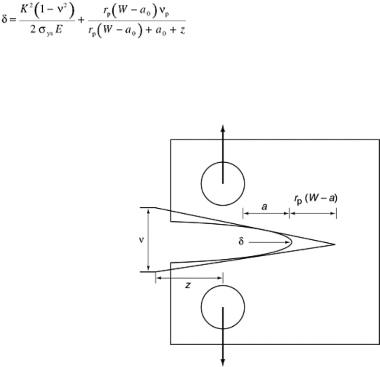
the formulas for δ calculation use a combination of an elastic and a plastic component:
(Eq 11)
In this equation, the elastic component of δ is based on a K equivalence, and the plastic component is based on
a rigid plastic rotation of the specimen about a neutral stress point at r
p
(W - a
0
) from the crack tip. In Eq 11, ν
is Poisson's ratio, σ
ys
is the yield strength, r
p
is a rotation factor, ν
p
is a plastic component of displacement, W -
a
0
is the uncracked ligament length, and z is the distance from the clip gage measurement position to the front
face for an SE(B) specimen or to the load line for a C(T) specimen (Fig. 13). The rotation factor, r
p
, is 0.44 for
the bend specimen and a variable ranging from 0.46 to 0.47 for the compact specimen.
Fig. 13 Definitions of length parameters used in plastic CTOD
For many years the CTOD test was the only one that measured toughness for a brittle, unstable fracture event
using a nonlinear fracture parameter. Now fracture toughness can be measured for unstable fracture using J in
ASTM E 1820. The ASTM E 1290 method also allows the measurement of toughness after a pop-in, which is
described as a discontinuity in the load-versus-displacement record usually caused by a sudden, unstable
advance of the crack that is subsequently arrested.
References cited in this section

5. A.A. Wells, Unstable Crack Propagation in Metals: Cleavage and Fast Fracture, Proc. Cranfield Crack
Propagation Symposium, Vol 1, Paper 84, 1961
9. “Standard Method for J
Ic
, a Measure of Fracture Toughness,” E 813, Annual Book of ASTM Standards,
Vol 3.01, ASTM
10. “Standard Method for Determining J-R Curves,” E 1152, Annual Book of ASTM Standards, Vol 3.01,
ASTM
11. “Standard Test Method for Measurement of Fracture Toughness,” E 1820, Annual Book of ASTM
Standards, Vol 3.01 ASTM
12. “Methods for Crack Opening Displacement (COD) Testing,” BS5762: 1979, The British Standards
Institution, 1979
13. “Standard Method for Crack-Tip Opening Displacement (CTOD) Fracture Toughness Measurement,” E
1290, Annual Book of ASTM Standards, Vol 3.01, ASTM
Fracture Toughness Testing
John D. Landes, University of Tennessee, Knoxville
New Standards for Metallic Materials
The development of standard fracture toughness test methods is not completed. In the past five years, two new
standards have been developed, successfully balloted, and placed in the Annual Book of ASTM Standards. They
are the common test method, a new fracture toughness standard that combines most of the standard test
methods discussed above into a single standard, and the transition fracture toughness standard. A standard for
testing of weldments is still being developed.
Common Fracture Toughness Test Method
Because the J
Ic
and J-R curve test standards are similar in many respects, they have been combined into a single
test standard, ASTM E 1820 (Ref 11). This standard method also allows a measurement of fracture toughness
using the linear elastic parameter, K, and the nonlinear parameters, J and δ. The idea of a common method is
that most of the fracture toughness tests use the same specimens, instrumentation, and test procedures.
However, the analysis part of the standard gives each an exclusive quality that was derived from the historical
development of the fracture mechanics methodology. The way individual methods were written in the past
allows for the likelihood that a test can produce an invalid or unqualified result with no way to use the analysis
procedure of another test method to try to obtain an acceptable result. The common method combines all
measurements of fracture toughness into a single standard instead of many specialized standards. Therefore,
after the test has been completed, the behavior of the material can dictate the nature of the analysis used, and a
satisfactory fracture toughness result can be achieved for most tests. The analysis can use a linear elastic or an
elastic-plastic parameter; it can use a single point fracture measurement or an R-curve toughness measurement.
The way that each test is evaluated depends on the nature of the deformation and fracture behavior during the
test. Therefore, the actual test result has a major influence on how the data are analyzed.
An additional feature of the new common method is an initialization procedure to assure that the initial portion
of the J-R curve is aligned properly with the initial measured crack length. The ASTM E 813 method of J
Ic
measurement did not specifically align the initial portion of the curve and could give artificially raised or
lowered values of J
Ic
reflecting the misalignment in the initial J-R curve. The ASTM E 1820 method includes
