ASM Metals HandBook Vol. 8 - Mechanical Testing and Evaluation
Подождите немного. Документ загружается.

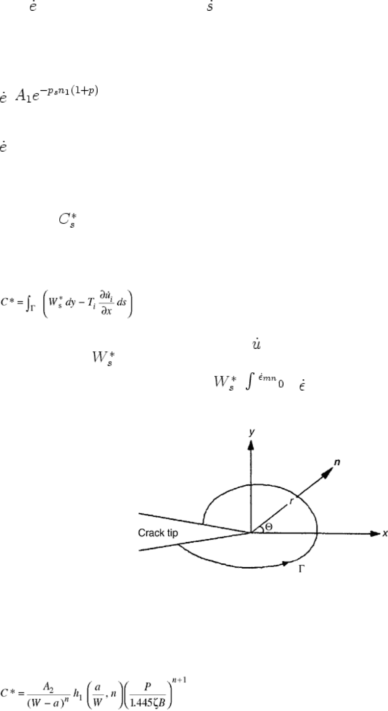
where is the engineering creep strain rate, is the applied engineering stress rate, e is the engineering strain, s
is the engineering (nominal) stress, E is Young's modulus, A
1
is the primary creep coefficient, p and n
1
are the
primary creep exponents, A
2
is the secondary creep coefficient, and n is the secondary creep exponent.
Under extensive creep conditions, the first term in Eq 1 can be neglected. This term is due to the elastic strain
rate, which is only of importance during small-scale creep. The second term is due to primary creep, and thus,
under extensive primary creep conditions, Eq 1 can be reduced to:
=
(Eq 2)
Similarly, the third term is due to secondary creep, and so under extensive secondary creep conditions, Eq 1
reduces to:
= A
2
s
n
(Eq 3)
All of the coefficients and exponents in the above equations may be obtained from creep deformation test
results.
C* Parameter. The conditions for the application of C* can be described as extensive secondary creep
conditions (Ref 1). In cases where the pure secondary creep condition is emphasized, one might see the use of
the notation instead of C*. The level of load and, accordingly, the characterization of the loading have a
negligible effect on the material behavior because, under extensive creep conditions, the creep strain rate
dominates the elastic or plastic strain rate throughout the cracked specimen (Ref 1). The C* parameter is
analogous to the path-independent J-integral discussed previously. The basic definition of the integral, as given
by Landes and Begley (Ref 13), Nikbin et al. (Ref 14), and Taira et al. (Ref 15) is as follows:
(Eq 4)
where Γ is a counter-clockwise contour of the integral that encloses the crack tip (Fig. 2), T
i
is the outward
stress vector acting on the contour around the crack,
i
is the displacement rate vector, and ds is an increment
of the contour path. is the strain energy rate density defined by the equation:
= σ
ij
d
ij
Overall, C* is a calculation of the energy input rate in the crack-tip area, similar to the J-integral. It could also
be referred to as the stress-power dissipation rate in the cracked body (Ref 13).
Fig. 2 Schematic of the contour integral in terms of crack-tip coordinate system used to define C*. n is
the unit normal vector. Source: Ref 5
An approximation for estimating C* can be found in the Electric Power Research Institute (EPRI) Handbook
solution (Ref 1). In this case, C* is indirectly calculated from the material power-law creep constants, A
2
and n,
from Eq 3. When under plane strain conditions, the equation for a compact-type (CT) specimen is given by:
(Eq 5)
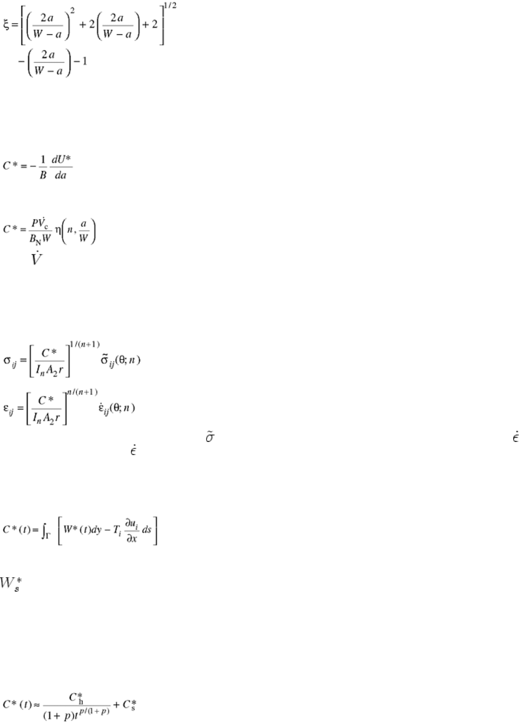
with
(Eq 6)
where W is the compact tension specimen width, a is the crack length, P is the applied load, B is the thickness
of the cracked body, and h
1
is a function of a/W and the strain-hardening exponent (the numerical values of h
1
can be found in Ref 16).
In addition, C* can also be described as the energy input rate difference between two identically loaded bodies
with incrementally differing crack lengths, da:
(Eq 7)
where U* is the power input in the cracked body. From this last equation, an expression has been derived for
experimentally determining C*:
(Eq 8)
where
c
is the load-line deflection due to creep, B
N
is the net specimen thickness (in side-grooved specimens,
B
N
is equal to the distance between the roots of the grooves), and η is a function of crack length, the exponent
on stress in Norton's creep equation, and specimen geometry (Ref 1).
Because as the cracked body is under extensive secondary creep conditions and the stress and strain rates are
related by Eq 3, the crack-tip stress and strain rate fields can be described in terms of C* as follows (Ref 17,
18):
(Eq 9)
(Eq 10)
where I
n
is a dimensionless factor (Ref 19),
ij
(θ; n) is the dimensionless stress angular distribution (Ref 19),
ij
is the strain rate tensor, and
ij
(θ; n) is the dimensionless strain rate angular distribution.
C*(t) Parameter. For the C*(t) parameter, the conditions are extensive primary and/or secondary creep
conditions (Ref 1). Again, the level of the load has little effect on the material behavior. The C*(t) parameter is
essentially the extension of C* from extensive secondary creep conditions into extensive primary creep
conditions. This parameter can be defined as:
(Eq 11)
where W*(t) is the instantaneous stress-power or energy rate per unit volume.
One can see in Eq 11 that when the specimen is under pure secondary creep conditions, W*(t) is replaced by
, and thus, C*(t) is equal to C* (as shown in Eq 4).
Conditions of extensive creep are not always associated with pure secondary or pure primary creep. Often, a
mixture of primary and secondary creep is found. Under such conditions, the C*(t) integral is no longer path
independent. However, an approximation of C*(t) can still be calculated path-independently with an error of
2% (Ref 20).
Under extensive primary-secondary creep conditions, the value of C*(t) can also be approximated by the sum
of C*(t) under extensive primary creep conditions and C*(t) or C* under extensive secondary creep conditions.
This approximation is given by:
(Eq 12)
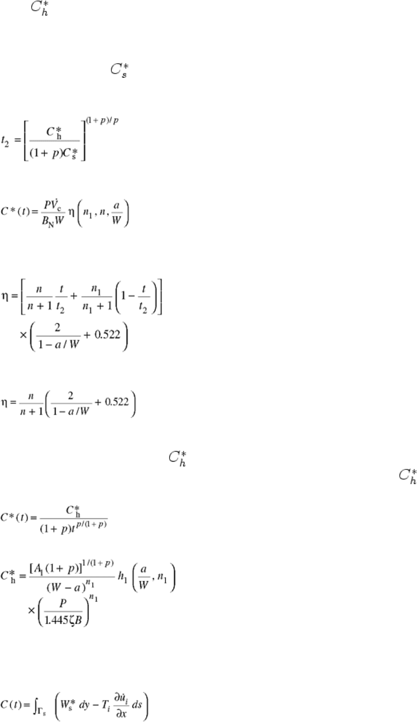
where is the stress-dependent part of the path-independent integral C*(t) under extensive primary creep
conditions. In Eq 12, the first term on the right-hand side is the value of C*(t) under extensive pure primary
creep conditions, while the second term is the C*(t) or C* value under extensive pure secondary creep
conditions. Another expression of Eq 12 would be:
C* (t) ≈ [1 + (t
2
/t)
p/(1+p)
]
(Eq 13)
where t
2
is the time of the transition from extensive primary creep to extensive secondary creep. Here t
2
can be
determined by:
(Eq 14)
Knowing that C* can be estimated experimentally from Eq 8, C*(t) can similarly be measured in test specimens
under extensive secondary creep conditions using this equation:
(Eq 15)
Equation 15 differs from Eq 8 in that the function, η, is a function of the primary creep exponent, n
1
, in addition
to the secondary creep exponent, n, and the ratio of crack size to specimen width, a/W. The expression for η is
given by (Ref 21):
(Eq 16)
For CT specimens, it has been shown that there is little dependence of η on n and n
1
. For this reason, it is
recommended that for these specimens, η can be approximated using the following equation (Ref 22):
(Eq 17)
This equation has been adopted by ASTM E 1457, “Standard Test Method for Measurement of Creep Crack
Growth Rates in Metals” (Ref 23).
C*
h
Parameter. The conditions for can be expressed as extensive primary creep conditions (Ref 1). This
parameter was defined as a path-independent integral by Riedel (Ref 24). As such, is the stress-dependent
part of C*(t) under extensive primary creep conditions shown as:
(Eq 18)
C*
h
can be determined by the equation:
(Eq 19)
C(t) Parameter. The conditions for the C(t) parameter are frequently found at the crack tip. These conditions
can be described as small-scale, elastic, primary and/or secondary creep conditions (Ref 1). Ohji et al. (Ref 25),
Bassani and McClintock (Ref 26), and Ehlers and Riedel (Ref 27) studied the crack-tip stress fields under these
conditions, and the C(t) integral was defined as follows:
(Eq 20)

where Γ
s
is a counter-clockwise contour of the integral that encloses the crack within the crack-tip creep zone.
This differs from the counter-clockwise contour of the C* integral because, in that case, the contour of the
integral was not limited to the crack-tip creep zone. The reason for this limitation is that it is only in the creep
zone that the creep strain rate may dominate the elastic strain rate. The loading is confined to elastic loading for
this parameter due to the fact that the creep strain rate may not be able to dominate the plastic strain rate under
small-scale creep zone conditions. This is because the plastic zone size may be larger than the creep zone size.
Just from the definition of the C(t) parameter, it is evident that when the creep zone scale transitions from small
to extensive conditions, the definition of the parameter becomes indistinguishable from that of the C*t)
parameter.
When experiencing small-scale, elastic, secondary creep conditions in the case of plane strain, the value of C(t)
can be approximated by this equation (Ref 25, 26, and 27):
(Eq 21)
where K is the stress intensity factor, and ν is Poisson's ratio.
Another approximation for C(t) under the same conditions is given as (Ref 27):
C(t) = [1 + t
T
/ t]
(Eq 22)
where t
T
is the transition time from small-scale to extensive creep given by the equation:
(Eq 23)
The approximations from Eq 22 have been confirmed in several numerical studies and have been determined to
be reasonably accurate (Ref 20, 28).
When under small-scale, elastic conditions with primary and/or secondary creep conditions, the C(t) parameter
can be approximated as follows (Ref 20, 29):
C(t) = [1 + t
TP
/t + (t
2
/ t)
p/(1 + p)
]
(Eq 24)
where t
TP
is the transition time from the small-scale primary creep to extensive primary creep conditions as
determined by:
(Eq 25)
For creep deformation ranging from small-scale to extensive creep, Ehlers and Riedel (Ref 27) proposed that
C(t) can be determined from the sum of the small-scale and extensive creep solutions as follows:
(Eq 26)
Their analytical work, along with that of Ohji et al. (Ref 25), shows that similar to C* for the extensive,
secondary creep conditions, C(t) may be used to describe the crack-tip stress and strain fields under the small-
scale, elastic creep conditions:
(Eq 27)
(Eq 28)
Even though C(t) can be applied to both small-scale and extensive creep conditions, this parameter has a severe
drawback. The values of C(t) can only be calculated with the given equations and cannot be experimentally
measured, as was the case with C* and C*(t). In addition, the accuracy of its calculated values depends heavily
on the accuracy of the constitutive equations employed for the calculation (Ref 1).
C
st
(t) Parameter. The conditions for the C
st
(t) parameter can be described as small-scale, elastic, primary and/or
secondary creep conditions during the time shortly after t
1
is reached and long before t
2
is reached (Ref 1). In
this case, t
1
is the transition time from small-scale primary creep in the elastic field to extensive primary creep
conditions. McDowell et al. (Ref 30) have shown that in a compact tension (CT) specimen during this time,
C(t) becomes essentially path independent because a stationary stress field is achieved across the remaining
ligament. Under such conditions, C(t) is defined as C
st
(t), and can be determined from the following equation:
C
st
(t) = [1 + (t
2
/t)
p/(1 + p)
]
(Eq 29)
C
t
Parameter. For C
t
, the conditions can best be described as small-scale or transition, elastic, and primary
and/or secondary creep conditions (Ref 1). The C
t
parameter was originally proposed by Saxena (Ref 31) in
order to avert the disadvantage of C(t), which cannot be experimentally measured. This parameter can be
thought of as an extension of the C* integral into the small-scale and transition creep regions, and, under
extensive creep conditions, the C
t
parameter approaches the value of C*(t) in much the same way as the C(t)
parameter does (Ref 1). Under small-scale conditions, however, the C
t
parameter behaves differently from C(t).
Whereas C(t) is the amplitude of the crack-tip stress field, C
t
, as defined by Saxena, is uniquely related to the
rate of expansion of the creep zone size under small-scale creep conditions (Ref 28):
(Eq 30)
where (C
t
)
SSC
is the value of C
t
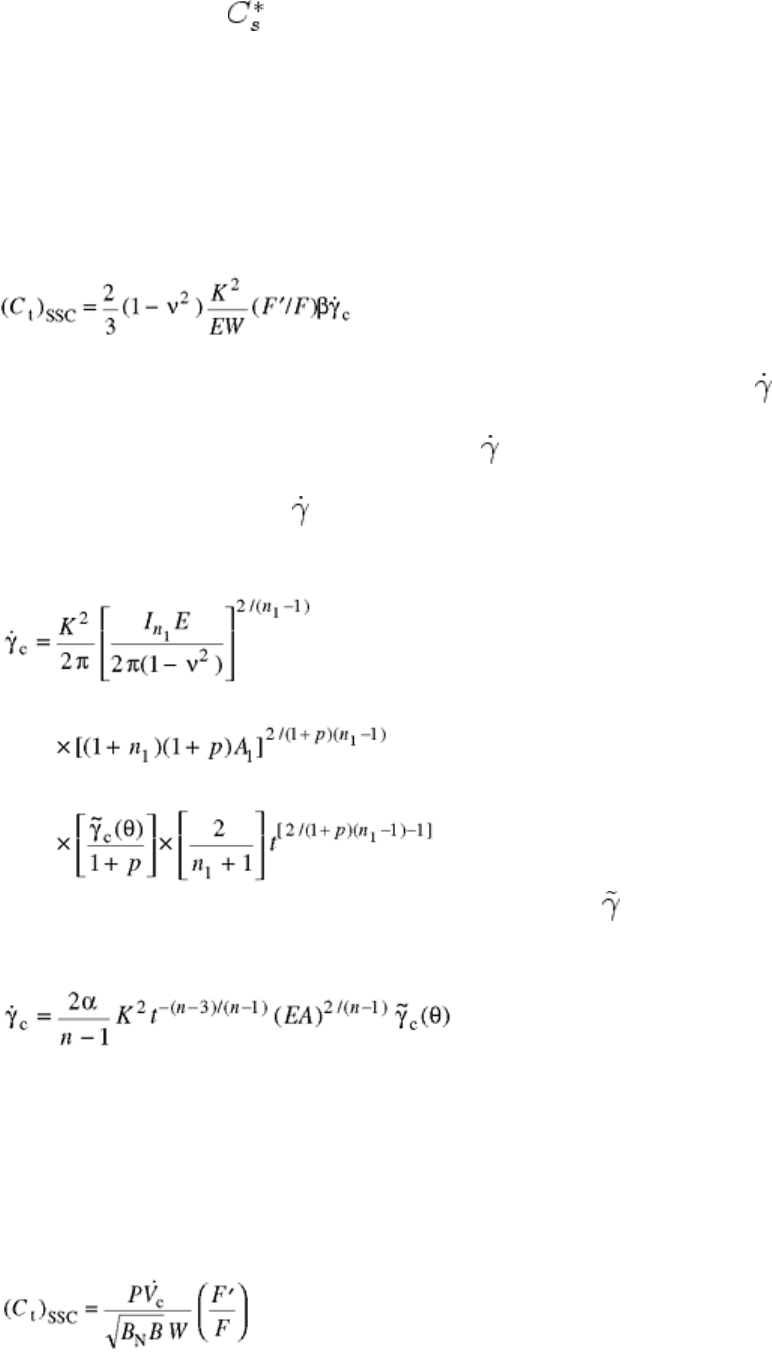
when the small-scale creep condition is emphasized, F is the K-calibration
factor [F = (K/P)BW1/2], F′ is the a/W derivative of F [F′ = dF/da(a/W)], and
c
is the rate of expansion of the
creep zone size.
For the rate of expansion of the creep zone size,
c
, expressions have been derived for elastic, primary creep
and elastic, secondary creep conditions (Ref 21, 28). An analytical estimation of (C
t
)
SSC
may be found by
substituting the corresponding
c
expressions into Eq 30 (Ref 1).
When the specimen is under small-scale, elastic primary creep conditions, the rate of expansion of the creep
zone is given by the following equation:
(Eq 31)
where I
n1
is a nondimensional factor dependent upon n
1
, and
c
(θ) is the dimensionless function defining the
creep zone shape (Ref 1).
Under small-scale, elastic secondary creep conditions, the rate of expansion of the creep zone size is given by:
(Eq 32)
where α is a dimensionless constant dependent on n.
C
t
may also be estimated over a range, from small-scale to extensive creep conditions, using the following:
C
t
= (C
t
)
SSC
+ C* (t)
(Eq 33)
where (C
t
)
SSC
and C*(t) are both calculated rather than experimentally measured values. Again, it is important
to note that C
t
changes from (C
t
)
SSC
to C*(t) as conditions progress from small-scale to extensive creep (Ref 1).
An equation has been included in the ASTM handbook (Ref 23) that allows the experimental measure of C
t
under small-scale creep conditions. This equation is included as follows:
(Eq 34)

Parameters for Cyclic Loading
For cyclic loading, there are two parameters considered to be applicable for tests involving cyclic loading.
Again, the testing conditions, definitions, and necessary calculations for each parameter are outlined below.
ΔJ
c
Parameter. The ΔJ
c
parameter is simply a time integral of C* or J* over the hold time, t
h
, involved in
trapezoidal waveform loading (Ref 1). The parameter was first introduced by Jaske and Begley (Ref 32) and
Taira et al. (Ref 33) in order to correlate with the time-dependent creep crack growth during a trapezoidal
waveform loading at elevated temperatures. Its definition is:
ΔJ
c
= C* (dt)
(Eq 35)
where t
h
is the hold time at the maximum load of a trapezoidal load form.
When a material is subjected to trapezoidal waveform loading, its response can be divided into two parts: the
loading portion and the hold time portion. Creep deformation may occur at the crack tip during both portions.
When integrated over the hold time, the ΔJ
c
parameter gives the total energy input in the crack-tip area due to
creep deformation that occurs during the hold time (Ref 1). During the loading portion, the amount of creep
deformation generally depends on the rate of loading. If the loading is conducted quickly, the creep deformation
is small compared to the elastic and plastic deformation. Thus, it is usually a negligible effect, and, therefore,
no time-dependent fracture-mechanics parameter has been defined for such instances. However, in the case of
slow loading, creep deformation can dominate the elastic and plastic deformation. In this instance, Ohtani et al.
(Ref 34) and other researchers (Ref 35, 36, and 37) have proposed a method to use for estimation of ΔJ
c
. This
method functions on the assumption that creep deformation occurs under extensive creep conditions.
Because trapezoidal waveform loading involves both elastic and plastic deformations, the total energy output
for the entire cycle should be described by the sum of the cycle-dependent and time-dependent parts (Ref 1).
Therefore, the ΔJ
c
parameter can be integrated into the total J-integral (ΔJ
T
) defined as:
ΔJ
T
= ΔJ
f
+ ΔJ
c
(Eq 36)
where ΔJ
f
is the cycle-dependent integral associated with time-independent plasticity (Ref 1).
(C
t
)
avg
Parameter. The (C
t
)
avg
parameter is, as the notation denotes, the average value of the C
t
parameter during
the hold time periods of a trapezoidal waveform (Ref 1). The parameter was first defined by Saxena as the
following (Ref 38, 39, and 40):
(Eq 37)
The definition of the (C
t
)
avg
parameter given in Eq 37 is applicable only for creep deformation encountered
during the hold time, t
h
. In general, along with the creep deformation during this time, there is elastic
deformation as a result of stress relaxation. With longer hold times, the creep zone expands from small-scale to
extensive creep, so eventually the elastic deformation will become insignificant. As can be seen through Eq 37,
as C
t
approaches C*, (C
t
)
avg
· t
h
becomes equal to ΔJ
c
(Ref 1). It is important to note, however, that under small-
scale creep conditions, the (C
t
)
avg
· t
h
and ΔJ
c
parameters will not be equal. This is especially true when the
values are calculated as opposed to being experimentally obtained (Ref 1).
According to which method is used to estimate the deflection rate of the cracked body, there are two ways to
determine the value of (C
t
)
avg
. For a CT specimen test, where the load and load-line deflection as functions of
time can be determined experimentally, the value of (C
t
)
avg
is experimentally measured. However, for the case
of a cracked component, where the deflection rate can only be predicted analytically, (C
t
)
avg
is found by
calculation.
When measured experimentally, (C
t
)
avg
can be obtained from the following:
(Eq 38)
where ΔP is the applied load range and ΔV
c
is the load-line deflection due to creep during the hold period.
The value of (C
t
)
avg
, when determined analytically, is found through the employment of equations that depend
on material conditions. If a material has low resistance to cyclic plasticity, where the cyclic plastic zone is
larger than the creep zone during the first hold time, (C
t
)
avg
may be determined from the following equation
(Ref 39) as elastic-cyclic plastic-secondary creep conditions:
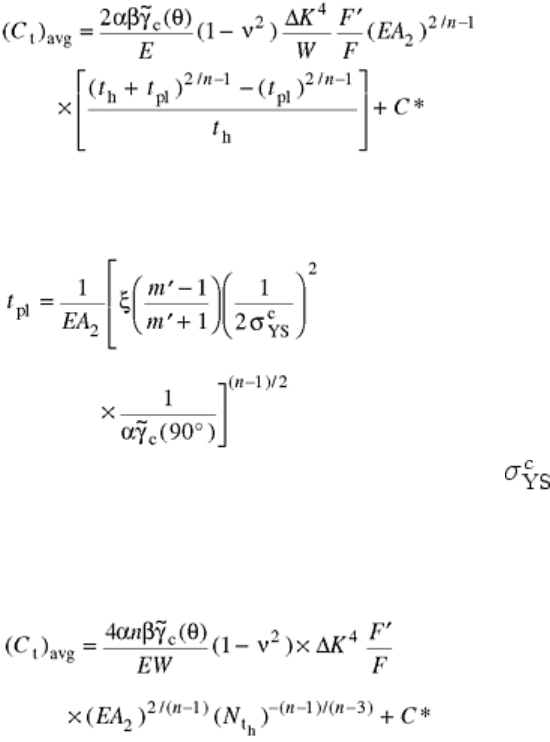
(Eq 39)
where ΔK is the range of the stress intensity factor, t
pl
is the factor added to account for retardation in the creep
zone expansion rate due to cyclic plasticity, and α and β are constants. In order to estimate t
pl
, the following
may be used:
(Eq 40)
where m′ is the cyclic strain-hardening exponent, is the cyclic yield strength determined as the stress
amplitude (Δσ/2) corresponding to a plastic strain amplitude (Δε
p
/2) of 0.2%, and ξ is a constant.
On the other hand, for materials having high resistance to cyclic deformations, where creep rates are high and
the creep zone size quickly exceeds the cyclic plastic zone size, the value of (C
t
)
avg
may be calculated from a
different equation (Ref 41):
(Eq 41)
where N is the number of fatigue cycles. For more detail concerning these last few equations, consult Ref 39
and 41.
References cited in this section
1. W. Ren, “Time-Dependent Fracture Mechanics Characterization of Haynes HR160 Superalloy,” Ph.D.
dissertation, School of Material Science and Engineering, University of Tennessee, 1995
5. R.H. Norris, P.S. Grover, B.C. Hamilton, and A. Saxena, Elevated Temperature Crack Growth, Fatigue
and Fracture, Vol 19, ASM Handbook, ASM International, 1996
12. A. Saxena, Fracture Mechanics Approaches for Characterizing Creep-Fatigue Crack Growth, Int. J.
JSME A, Vol 36 (No. 1), 1993, p 15, 16
13. J.D. Landes and J.A. Begley, A Fracture Mechanics Approach to Creep Crack Growth, Mechanics of
Crack Growth, STP 590, ASTM, 1976, p 128–148
14. K.M. Nikbin, G.A. Webster, and C.E. Turner, Relevance of Nonlinear Fracture Mechanics to Creep
Cracking, Cracks and Fracture, STP 601, ASTM, 1976, p 47–62
15. S. Taira, R. Ohtani, and T. Kitamura, Application of J-integral to High-Temperature Crack Propagation,
J. Eng. Mater. Technol. (Trans. ASME), Vol 101, 1979, p 154
16. V. Kumar, M.D. German, and C.F. Shih, “An Engineering Approach to Elastic-Plastic Analysis,”
Technical Report EPRI NP-1931, Electric Power Research Institute, 1981

17. J. Hutchinson, Singular Behavior at the End of a Tensile Crack in a Hardening Material, J. Mech. Phys.
Solids, Vol 16, 1968, p 13
18. J. Rice and G.F. Rosengren, Plane Strain Deformation near a Crack Tip in a Power-Law Hardening
Material, J. Mech. Phys. Solids, Vol 16, 1968, p 1–12
19. N.L. Goldman and J.W. Hutchinson, Fully Plastic Crack Problems: The Center-Cracked Strip Under
Plane Strain, Int. J. Solids Struct., Vol 11, 1975, p 575–591
20. C.P. Leung, D.L. McDowell, and A. Saxena, Consideration of Primary Creep at Stationary Crack Tips:
Implications for the C
t
Parameter, Int. J. Fract., Vol 36, 1988
21. A. Saxena, Creep Crack Growth in Creep-Ductile Materials, Eng. Fract. Mech., Vol 40 (No. ), 1991, p
721
22. P.K. Liaw, A. Saxena, and J. Schaefer, Estimating Remaining Life of Elevated Temperature Steam
Pipes, Part I: Material Properties, Eng. Fract. Mech., Vol 32, 1989, p 675
23. “Standard Test Method for Measurement of Creep Crack Growth Rates in Metals,” ASTM E 1457,
American Society for Testing and Materials, 1998
24. H. Riedel, Creep Deformation at Crack Tips in Elastic-Viscoelastic Solids, J. Mech. Phys. Solids, Vol
29, 1981, p 35
25. K. Ohji, K. Ogura, and S. Kubo, Stress-Strain Field and Modified J-Integral in the Vicinity of a Crack
Tip Under Transient Creep Conditions, Int. J. JSME, Vol 790 (No. 13), p 18, 1979
26. J.D. Bassani and F.A. McClintock, Creep Relaxation of Stress Around a Crack Tip, Int. J. Solids Struct.,
Vol 7, 1981, p 479
27. R. Ehlers and H. Riedel, A Finite Element Analysis of Creep Deformation in a Specimen Containing a
Macroscopic Crack, Advances in Fracture Research: Proc. of the Fifth Int. Conf. of Fracture, ICF-5
,Vol 2, Pergamon Press, 1981, p 691–698
28. J.L. Bassani, K.E. Hawk, and A. Saxena, Evaluation of the C
t
Parameter for Characterizing Creep Crack
Growth Rate in the Transient Regime, Time-Dependent Fracture, Vol 1, Nonlinear Fracture
Mechanics, STP 995, ASTM, 1986, p 7–26
29. H. Riedel and V. Hetampel, Creep Crack Growth in Ductile, Creep Resistant Steels, Int. J. Fract., Vol
34, 1987, p 179
30. D.L. McDowell and C.P. Leung, Implication of Primary Creep and Damage for Creep Crack Extension
Criteria, Structural Design for Elevated Temperature Environments—Creep, Ratchet, Fatigue and
Fracture, Pressure Vessel and Piping Division, Vol 163, July 23–27 1989 (Honolulu), American
Society of Mechanical Engineers
31. A. Saxena, Creep Crack Growth Under Nonsteady-State Conditions, ASTM STP 905, Seventeenth
ASTM National Symposium on Fracture Mechanics, American Society for Testing and Materials, 1986,
p 185–201
32. B.E. Jaske and J.A. Begley, An Approach to Assessing Creep/Fatigue Crack Growth, Ductility and
Toughness Considerations in Elevated Temperature Service, MPC-8, ASTM, 1978, p 391

33. S. Taira, R. Ohtani, and T. Komatsu, Application of J-Integral to High Temperature Crack Propagation,
Part II: Fatigue Crack Propagation, J. Eng. Mater. Technol. (Trans. ASME), Vol 101, 1979, p 162
34. R. Ohtani, T. Kitamura, A. Nitta, and K. Kuwabara, High-Temperature Low Cycle Fatigue Crack
Propagation and Life Laws of Smooth Specimens Derived from the Crack Propagation Laws, STP 942,
H. Solomon, G. Halford, L. Kaisand, and B. Leis, Ed., ASTM, 1988, p 1163
35. K. Kuwabara, A. Nitta, T. Kitamura, and T. Ogala, Effect of Small-Scale Creep on Crack Initiation and
Propagation under Cyclic Loading, STP 924, R. Wei and R. Gangloff, Ed., ASTM, 1988, p 41
36. R. Ohtani, T. Kitamura, and K. Yamada, A Nonlinear Fracture Mechanics Approach to Crack
Propagation in the Creep-Fatigue Interaction Range, Fracture Mechanics of Tough and Ductile
Materials and Its Application to Energy Related Structures, H. Liu, I. Kunio, and V. Weiss, Ed.,
Materials Nijhoff Publishers, 1981, p 263
37. K. Ohji, Fracture Mechanics Approach to Creep-Fatigue Crack Growth in Role of Fracture Mechanics
in Modern Technology, Fukuoka, Japan, 1986
38. K.B. Yoon, A. Saxena, and P.K. Liaw, Int. J. Fract., Vol 59, 1993, p 95
39. K. B. Yoon, A. Saxena, and D. L. McDowell, Influence of Crack-Tip Cyclic Plasticity on Creep-Fatigue
Crack Growth, Fracture Mechanics: Twenty Second Symposium, STP 1131, ASTM, 1992, p 367
40. A. Saxena and B. Gieseke, Transients in Elevated Temperature Crack Growth, International Seminar on
High Temperature Fracture Mechanics and Mechanics, EGF-6, Elsevier Publications, 1990, p iii–19
41. N. Adefris, A. Saxena, and D.L. McDowell, Creep-Fatigue Crack Growth Behavior in 1Cr-1Mo-0.25V
Steels I: Estimation of Crack Tip Parameters, J. Fatigue Mater. Struct., 1993
Creep Crack Growth Testing
B.E. Gore, Northwestern University, W. Ren, Air Force Materials Laboratory, P.K. Liaw, The University of Tennessee
Creep-Fatigue Crack Growth Testing
The following description of the experimental test method for creep crack growth tests using a compact
specimen geometry, under cyclic or static loading, is in agreement with the ASTM E 1457 “Standard Test
Method for Measurement of Creep Crack Growth Rates in Metals” (Ref 23). The aforementioned technique
entails applying a constant load to a heated, precracked specimen until significant crack extension or failure
occurs. During the test, the crack length, load, and load-line deflections must be monitored and recorded, and
upon test completion, the final crack length must be measured. Analysis of the test data involves an
examination of the crack growth rate with respect to time, da/dt, in terms of the magnitude of an appropriate
elevated-temperature crack growth parameter (Ref 5, 23). The various crack growth parameters are presented
earlier in this article.
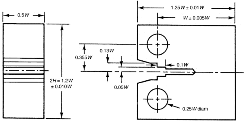
Specimen Configuration and Dimensions. The recommended specimen for creep crack growth testing is the CT
specimen. Figure 3 illustrates the specimen geometry, including details of the design specifications. Although
other configurations have also been used, such as the center-cracked tensile (CCT) panel and the single-edge
notch (SEN) specimen, the CT specimen is considered to be more suitable for creep and creep-fatigue crack
growth testing (Ref 5) and remains most convenient. In terms of suitability, the transition time for extensive
creep conditions to develop is longer in CT than in CCT specimens for the same K and a/W for samples of
identical width (Ref 42). Due to the extended transition time, during creep-fatigue testing, the necessary
condition that t
c
/t
1
« 1, with t
c
representing cyclic time, and t
1
being the aforementioned transition time, is more
easily met. In terms of convenience, an advantage of the CT specimen is that a clip gage can be easily attached
for the measurement of load-line deflection, which is one of the components required in the calculation of
crack-tip parameters. In addition, one of the most important advantages is that the magnitude of the applied
load needed to obtain a particular value of K is significantly lower for CT than for CCT specimens. Hence,
machines with smaller load capacities and small fixtures can be used for testing (Ref 5).
Fig. 3 Drawing of standard CT specimen. Source: Ref 22
Testing Machines. Three different types of machines can be used to run crack growth tests: dead-weight,
servomechanical, and servohydraulic machines. Regardless of the choice of machine, it is necessary to be able
to maintain a constant load over an extended period of time (variations are not to exceed ±1.0% of the nominal
load value at any time). Note that to fulfill this requirement, if lever-type, dead-weight creep machines are used,
care must be taken to ensure that the lever arm remains in a horizontal position. More detailed specifications of
the testing machine may be found in ASTM E 4, “Practices for Load Verification of Testing Machines” (Ref
43). Additionally, it is recommended that precautions be taken to ensure that the load is applied as nearly axial
as possible.
Control Parameter. For those tests run under creep-fatigue conditions where a trapezoidal waveform is
employed, a choice between testing conducted under a load-controlled or displacement-controlled conditions
must be made. Figure 4(a) shows a schematic representation of the displacement versus time and crack size
versus time for a load-controlled case. Displacement-controlled testing schematics of the load versus time and
crack size versus time are shown in Fig. 4(b) for comparison (Ref 5).
