ASM Metals HandBook Vol. 8 - Mechanical Testing and Evaluation
Подождите немного. Документ загружается.

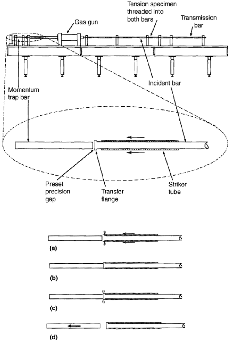
Fig. 1 Momentum trapping in recovery Hopkinson bar testing. (a) Momentum-trap tube MT in contact
with transfer flange F traps the tension pulse T upon reflection off the flange F. (b) Bar B in contact with
bar A traps compression pulse C. Source: Ref 7
Tension Hopkinson Bar with Momentum Traps. In a tension Hopkinson bar, the momentum trapping scheme
shown in Fig. 1(a) and (b) can be used to trap the compression pulse (Fig. 1b), which reflects off the sample,
back into the incident bar, and the tension pulse (Fig. 1a), which is transmitted through the sample into the
transmission bar, respectively.
Figures 2, 3, 4 show a complete system that includes at the loading end a tubular striker, an incident bar with a
transfer flange at its free end, a gas gun through which the incident bar passes, and a momentum-trap bar. The
far end of the transmission bar terminates in a momentum-trap tube (not shown), which is the mirror image of
the one shown in Fig. 1(a).
Fig. 2 Recovery tension Hopkinson bar setup. Source: Ref 7
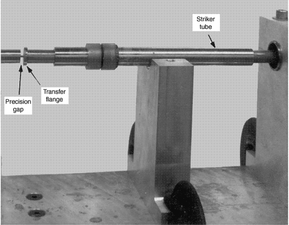
Fig. 3 Operation of the recovery tension Hopkinson bar. (a) Striker tube impacts transfer flange. (b) The
resulting tensile pulse closes the preset precision gap. (c) The compression pulse, which reflects off the
sample into the incident bar, reaches the transfer flange and is transmitted into the momentum-trap bar.
(d) The momentum in the trapped pulse causes the bar to fly off. Source: Ref 7
Fig. 4 Photograph of tension Hopkinson bar momentum-trap construction. Source: Ref 7
A preset precision gap separates the momentum-trap bar and the transfer flange of the incident bar. The
precision gap is set such that the end of the momentum-trap bar and the face of the transfer flange are brought
into contact, once the entire tensile pulse, produced by the tubular striker, is transferred into the incident bar
through the transfer flange. This tensile pulse then travels toward the sample, where it is partly transmitted into
the transmission bar and is partly reflected as compression back into the incident bar. This reflected
compression (often nearly the same as the incident pulse) is then transmitted into the momentum-trap bar and
reflects off the other (free) end of this bar as a tensile pulse. This pulse is then trapped in the momentum-trap
bar since the contact interface with the transfer flange cannot support tension. The momentum of the trapped
pulse causes the bar to fly off. The incident bar then is everywhere at rest. The pulse, which is transmitted
through the sample into the transmission bar, is also trapped at the free end of this bar by a momentum-trap
tube. This free end of the transmission bar includes a transfer flange and a momentum-trap tube in contact with
the flange, similar to those in Fig. 1(a).
At the striker end of the incident bar, the precision gap between the transfer flange and the momentum-trap bar
must be calculated and set with some care to obtain satisfactory results, as illustrated in Fig. 5(a). If the gap is
too large, the reflected compression pulse in the incident bar will not be transmitted to the momentum-trap bar.
On the other hand, if the gap is too small, it will be closed during the loading of the incident bar by the striker.
This affects the stress pulse, moves the momentum-trap bar into an improper position, and, hence, produces
undesirable results. An example is shown in Fig. 5(b), where the gap was much too large.
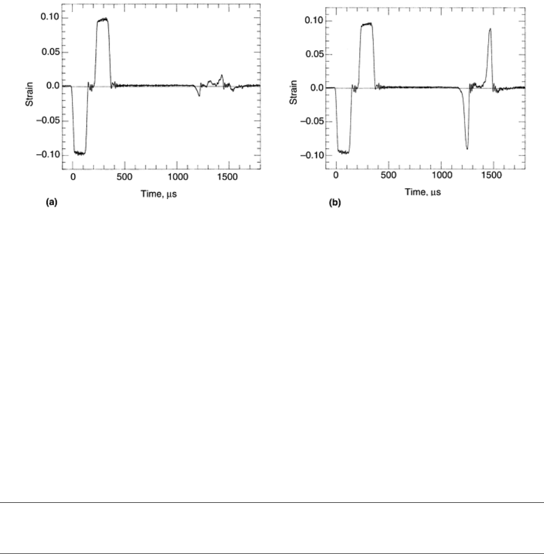
Fig. 5 (a) A typical tensile stress pulse, its reflected compression pulse, and its residue after trapping. (b)
A poorly trapped reflected compression; the gap between the momentum-trap and incident bars was too
big. Source: Ref 7
The momentum-trap bar is correctly positioned when the gap is set such that when the initial collision between
the striker and the incident bar is complete, the incident bar is fully in contact with the momentum-trap bar.
While the necessary separation can be calculated, in practice this provides a starting point that then is optimized
by trial and error. If the breech pressure of the gas gun and the striker velocity are kept constant while adjusting
the gap, within a few trials the correct gap for a given striker bar and breech pressure will be obtained. With
data of this kind, a calibration curve of breech pressure versus gap can be established for further use.
Calibration curves of this kind are not universal and must be rechecked periodically for the same system and
reestablished each time a change in the system is made.
Reference cited in this section
7. S. Nemat-Nasser, J.B. Isaacs, and J.E. Starrett, Hopkinson Techniques for Dynamic Recovery
Experiments, Proc. R. Soc. (London) A, Vol 435, 1991, p 371–391
Recovery Hopkinson Bar Techniques
Sia Nemat-Nasser, University of California, San Diego
Stress-Reversal and Strain Rate Jump Hopkinson Techniques
Using a flange and a momentum-trap tube, it is possible to produce a compression pulse followed by a tension
pulse and to create a sudden jump (an increase or a decrease) in the strain rate. These techniques are discussed
in this section.
Stress-Reversal Technique. Figure 6 shows the overall design of this stress-reversal Hopkinson bar. The loading
end of the incident bar begins with a transfer flange, as shown in Fig. 6 and 7 (see also Fig. 8). In this setup, the
incident tube, the striker bar, and the incident bar have the same impedance. The incident tube rests against the
transfer flange at one end and against a reaction mass at the other, as shown in Fig. 6 and 7. The reaction mass
is a large steel cylinder through which the incident bar passes.
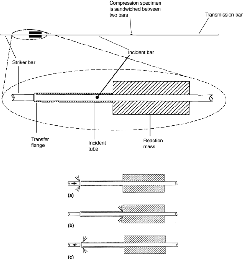
Fig. 6 A stress-reversal Hopkinson bar setup. Source: Ref 7
Fig. 7 Operation of stress-reversal Hopkinson bar. (a) Striker bar impacts transfer flange. (b)
Compressive pulse in the incident tube reflects from the reaction mass. (c) Striker bar bounces away.
Source: Ref 7
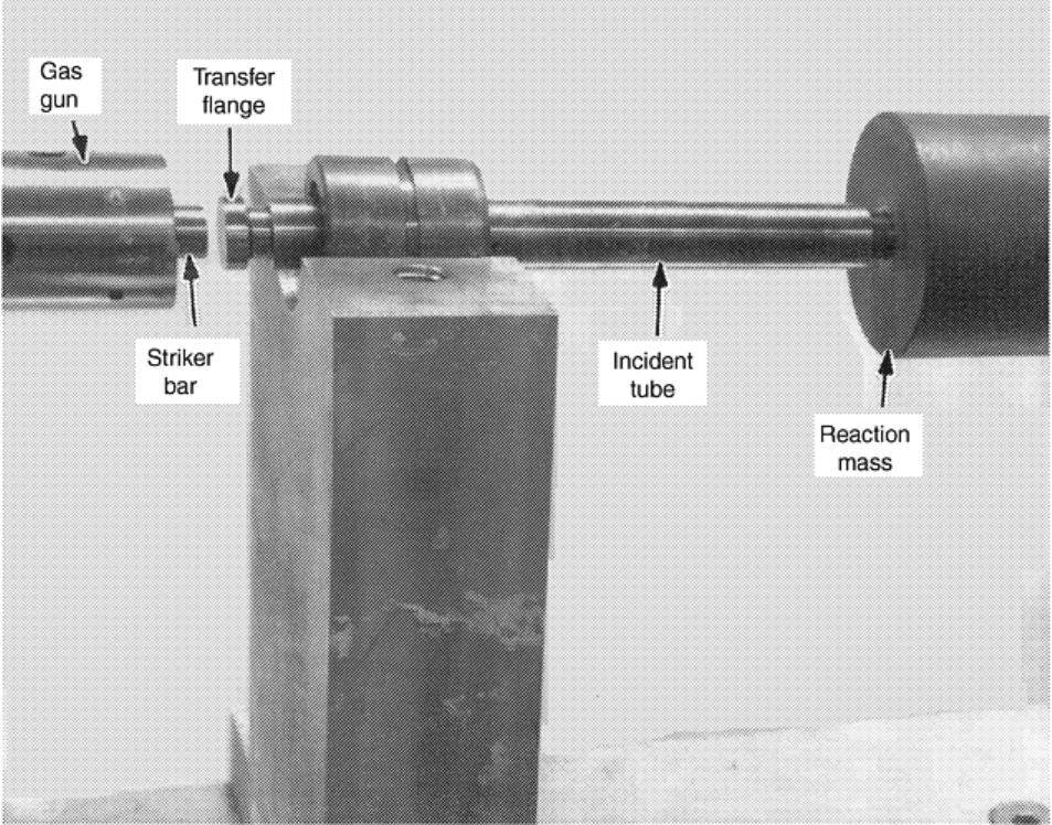
Fig. 8 Photograph of a stress-reversal loading fixture. Source: Ref 7
When the striker bar impacts the transfer flange at velocity V
0
, it imparts a common axial strain to the incident
tube and incident bar. The compression pulse in the incident bar travels along this bar toward the specimen. The
compression pulse in the incident tube reflects from the reaction mass as compression and reaches the transfer
flange at the same instant that the tension release pulse—which is reflected from the free end of the striker—
reaches the end of the striker bar in contact with the transfer flange. Since the combined cross section of the
incident bar and tube is twice that of the striker bar, having the same material properties, the striker bar begins
to bounce back, away from the transfer flange, as the transfer flange is loaded by the compression pulse
traveling along the incident tube. This compression pulse then imparts a tensile pulse to the incident bar, which
follows the then-existing compression pulse in the incident bar, both pulses traveling toward the sample. Figure
9 illustrates a typical result.
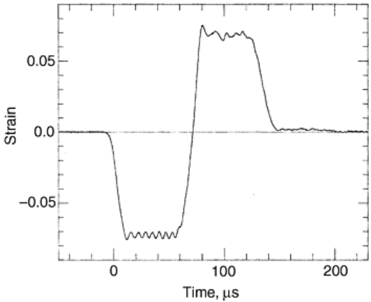
Fig. 9 A typical stress pulse generated by the stress-reversal Hopkinson bar technique. Source: Ref 7
It is important to bear in mind the significance of the perfect impedance matching of the striker bar, incident
bar, and incident tube, as well as the configuration of the transfer flange in the design of the loading fixture for
proper functioning of the stress-reversal Hopkinson technique.
From the equality of particle velocities at contacting surfaces and the conservation of linear momentum, it
follows that the particle velocity in the incident bar and incident tube at impact is V
0
/3. The particle velocity of
the compressed portion of the striker bar, relative to its unstressed part, then is 2V
0
/3. When the reflected
release-wave front in the striker reaches the contact with the transfer flange, the striker bar begins to move at
velocity V
0
/3 away from the transfer flange. At the same instant, the compression wave in the incident tube
imparts to the transfer flange exactly the same particle velocity (i.e., V
0
/3) in exactly the same direction. Thus,
the contact surfaces remain in contact for a short period, t
0
= 2l
0
/C
0
, until the striker separates at a third of its
initial impact velocity, as the flange comes to rest; here, l
0
is the common length of the striker bar and the
incident tube, and C
0
is their common longitudinal elastic-wave speed.
Strain Rate Jump. The stress-reversal technique can be used to change the strain rate during the course of
Hopkinson bar compression or tension experiments (Ref 14). Consider a recovery compression system first.
The loading (striker) end of the incident bar includes a transfer flange, an incident tube, and a reaction mass, as
sketched in Fig. 10(a). Suppose the transfer tube is in contact with the transfer flange. Then, as the striker bar
impacts the incident bar over the transfer flange, elastic compressive stresses are induced in both the incident
bar and the incident tube, as well as in the striker bar, in accordance with their impedances. To change
(decrease) the stress (and, hence, the strain) in the incident bar in the course of the experiment, a predetermined
gap is introduced between the transfer flange and the incident tube (Fig. 10b). As the striker bar now impacts
the incident bar, a compressive stress pulse is imparted into this bar, resulting in the shortening of the bar. Once
the incident bar is sufficiently shortened to come in contact with the incident tube over the transfer flange, a
stress pulse is also imparted into the incident tube, reducing the compressive stress (and, hence, the
compressive strain) in the incident bar. Since the sample strain rate is a linear function of the incident strain in
the incident bar, the procedure allows implementation of a change in the sample strain rate during the course of
the experiment. By proper choice of the gap and the involved impedances, a desired change in the sample strain
rate can be achieved.
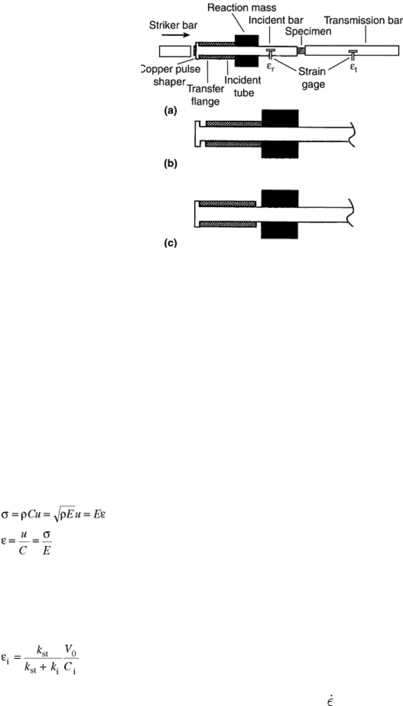
Fig. 10 Recovery Hopkinson bar compression testing. (a) Test configuration. (b) A gap between the
incident tube and the transfer flange leads to a decrease in the strain rate, once the gap is closed. (c) A
gap between the incident tube and the reaction mass leads to an increase in the strain rate. Source: Ref 8
It is also possible to increase the sample strain rate using the same construction. For this purpose, the incident
tube first rests against the transfer flange, as the striker bar impacts the flange (Fig. 10c). If the length of the
incident tube is suitably smaller than that of the striker, and if the other end of this tube (which is not in contact
with the transfer flange) is free, the compressive pulse in the tube will be reflected off its free end as a tensile
release pulse, reaching the transfer flange before the tensile release wave in the striker reaches there. The
incident tube then separates from the transfer flange while the striker bar continues to impart a stress pulse into
the incident bar. Upon separation of the tube from the flange, the stress (and, hence, the strain) in the incident
bar is increased accordingly. Thus, the incident strain at the sample-incident bar interface is increased, resulting
in a corresponding increase in the sample strain rate.
For numerical estimates, ρ, C, E, A, u, ε, and σ denote the mass density, longitudinal wave speed, Young's
modulus, area, particle velocity, axial strain, and axial stress, respectively, and subscripts st, i, and tb represent
the striker bar, incident bar, and the incident tube, respectively. Set k = ρCA, and note that C
2
= E/ρ.
Since the bar and the tube remain elastic throughout the experiment, in general:
(Eq 1)
While a gap separates the incident tube and the transfer flange (Fig. 4b):
k
i
u
i
= k
st
u
st
V
0
- u
st
= u
i
(Eq 2)
where V
0
is the (constant) initial velocity of the striker bar. From Eq 1 and 2, it follows that:
(Eq 3)
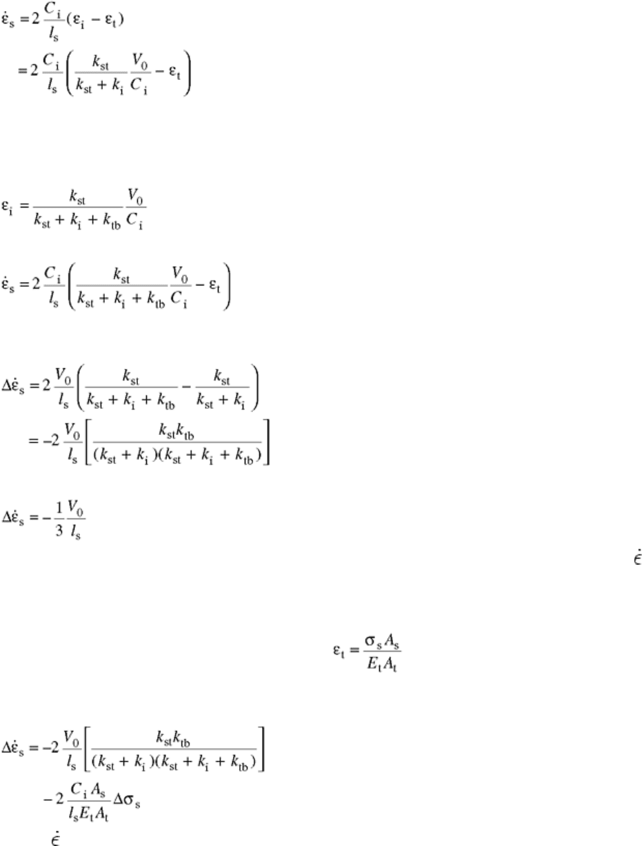
This strain in the incident bar is the incident strain at the sample end of the incident bar. If the strain in the
transmission bar is denoted by ε
t
, then the strain rate in the sample,
s
, is given by:
(Eq 4)
where l
s
is the sample length. Note that, in general, the incident and transmission bars have common area, wave
speed, and so on.
When the gap between the transfer flange and the incident tube is closed (Fig. 10c), the incident strain is
reduced to:
(Eq 5)
resulting in the sample strain rate of:
(Eq 6)
If the sample material is rate independent, ε
t
will be the same in Eq 4 and 6, and the change in the sample strain
rate becomes:
(Eq 7)
When k
st
= k
i
= k
tb
:
(Eq 8)
For example, with a striker velocity of 30 m/s (98 ft/s) and sample length of 5 mm (0.2 in.), Δ
s
= 2 × 10
3
s
-1
.
Note that these results apply to both reduction and increase in the sample strain rate.
For rate-dependent materials, the flow stress changes with the strain rate. Hence, the transmitted strain ε
t
in the
transmission bar is changed:
where subscripts s and t refer to the sample and transmission bar, respectively. Hence, if the change in the
sample flow stress is Δσ
s
:
(Eq 9)
where Δ
s
is negative when the strain rate (and, hence, the flow stress) is decreased.
Figure 11 illustrates the results of this method. Point A on the lower curve in this figure marks the strain in the
sample, at which the strain rate is changed from about 1600 s
-1
to about 850 s
-1
; the strain rate difference is
about 750 s
-1
. The impact velocity of the striker bar is 8 m/s (26 ft/s); the Young's modulus of the incident bar is
200 GPa (29 × 10
6
psi). The diameter of the transmission bar is 1.27 cm (0.5 in.). The length of the sample is
0.35 cm (0.14 in.). The stress difference in Fig. 11 due to the change of the strain rate is 350 MPa (50 ksi).
From Eq 9 and these data, a strain rate difference of 757 s
-1
is obtained (Ref 8). This calculated result is very
close to the observed one.
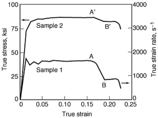
Fig. 11 Illustration of strain rate jump. At point A the strain rate is changed from about 1600 s
-1
to about
850 s
-1
, leading to a stress difference of about 350 MPa (50 ksi). Source: Ref 8
Strain Rate Jump in Tension. The tension bar with a momentum trap can be used to change the strain rate
during the course of tension Hopkinson tests. First, consider a case in which it is required to decrease the strain
rate during a test. To accomplish this, a gap is provided between the momentum-trap bar and the transfer flange
of the incident bar in Fig. 1(a) such that this gap is closed while the striker tube is transferring the load to the
transfer flange. By suitable choices of the impedances of the incident bar, momentum-trap bar, and the striker
tube, it is then possible to suddenly decrease the strain rate by a desired amount. The basic equations follow
from those given in the previous section.
To increase the strain rate in a tension Hopkinson test, a suitably short momentum-trap bar in contact with the
flange is used (Fig. 1a), before the striker tube impacts the transfer flange. Then, the striker bar imparts a tensile
pulse into the incident bar and, simultaneously, a compression pulse into the momentum-trap bar. This
compression pulse reflects off the other end of the momentum-trap bar as a tensile release wave, separating the
bar from the flange, once it reaches the contact between the bar and the flange. For a suitably long striker tube,
this can occur while the striker is continuing to load the transfer flange. Again, the necessary equations are
similar to those given in the previous section. Note that the impedances must be properly selected in order to
achieve a desired increase or decrease in the strain rate.
Recovery after Combined Compression-Tension Loading. In many high strain rate applications, materials may
be subjected to dynamic compressive loads, followed by tension. An example is the examination of the
dynamic Bauschinger effect and its relation to the microstructure of the material. Experimental investigations of
this kind require techniques to recover the sample after it has been subjected to a cycle of compression followed
by tension, or tension followed by compression.
The stress-reversal technique can be used to subject a specimen to a combined compression-tension pulse
without interruption and then recover it for post-test characterization (Ref 7). The loading fixture is the same as
shown in Fig. 6 7 8. The sample configuration and the manner by which it is attached to the incident and
transmission bars are designed such that, after the specimen is subjected to the desired compression-tension
pulse, it is detached from the incident bar without additional loading of its central gage portion. This process is
accomplished as follows.
As shown in Fig. 12 (see also photograph in Fig. 13), in addition to the reaction mass R
0
, there are two other
reaction masses, denoted by R
1
and R
2
. The sample construction (Fig. 14) includes two threaded ends and a
reaction flange F
S
, which, at the start of the experiment, rests against the reaction mass R
1
, with the sample end
fully threaded into the incident bar.
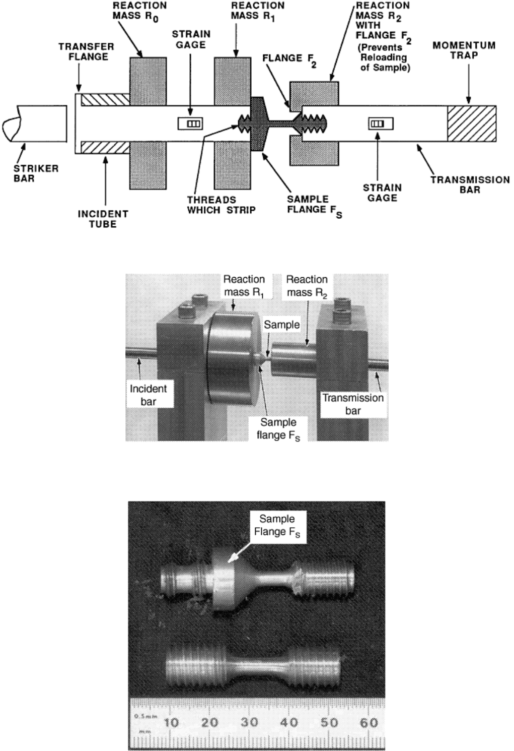
Fig. 12 Combined compression-tension dynamic recovery experiment. Source: Ref 7
Fig. 13 Photograph of combined compression-tension setup showing the manner by which the sample is
connected to the incident and transmission bars. Source: Ref 7
