Armstrong M., et al. Plurigaussian simulations in geosciences
Подождите немного. Документ загружается.

Gr
€
otsch and Mercadier (1999), cementation can specifically affect the core reef
exposed to the ocean but not the lee-side where porosity is preserved.
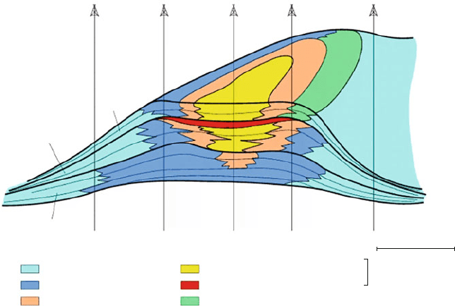
Six facies were differentiated for the simulation: fore reef (facies 1), core reef,
basin-ward (facies 2), back-reef (facie s 3), lagoon (facies 4), cemented facies
(facies 5), and core-reef landward (facies 6). Facies 5 corresponds to a cemented
horizon which affected facies 2, 3and 4in unitII. The cemented horizon constitutes
a significant permeability barrier within the reservoir, and so it is important to
reproduce it in the simulation. Three litho-stratigraphic units were then used for the
reservoir simulation, each with a specific facies distribution. The simulation was
processed in a proportional grid within a unit, in order to get correlation lines
parallel to the top and bottom of each unit.
InunitIII, the truncated gaussianalgorithm was usedwith a simplelithotype rule
(Fig. 8.8). In unit II, the plurigaussian algorithm was applied in order to respect the
complex relationship between the facies. The cemented facies (facies 5) can be in
contact with facies 2, 3 and 4 but facies 5 cannot be in contact with facies 1. The
vertical proportion curve also constrains facies 5 only to the topmost part of the unit
II. In unit I, the porous core reef (facies 6) is only present in the lee side oriented
towards the continent. The lithotype rule prevents contact between facies 6 and 4.
Gaussianvariogramswere used for thetwo gaussianfunctionsin orderto respectthe
rounded shape of the reef facies belts. The continuity of the facies distribution was
also ensured by using long variogram ranges of the 6,000 m in the East-West
direction and 15,000 m in the North-South direction. This anisotropy imposes an
ellipsoidal shape on the simulated reef. The results of the simulation are shown in
Unit II
Unit III
5
6
7
2
1
3
FACIES
: FORE-REEF
: REEF CORE (SEAWARD)
: BACK-FEED
: LAGOON
: CEMENTED LAYER
20m
0
0
1km
: REEF-CORE (LANDWARD)
2
2
3
4
3
6
1
1
2
2
3
3
3
4
5
1
1
1
Unit I
Fig.8.7 Synthetic model of a reef complex from which a pseudo-well data-base was compiled for
simulation purposes
130 8 Case Studies and Practical Examples
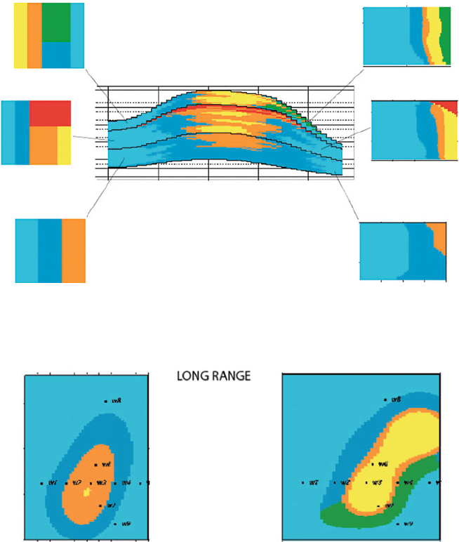
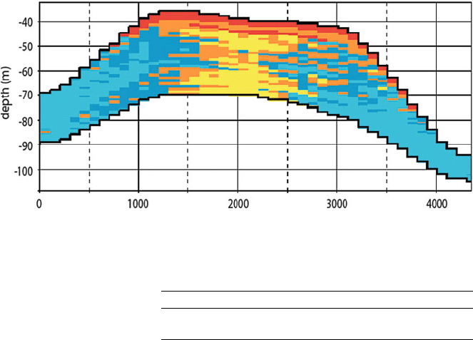
Fig. 8.8 in a vertical section across the reef, and in Fig. 8.9 in plan view. The
complexinternalorganisationof the reefhasbeenreproduced wellinthesimulation.
Simulating Progradational Patterns
In a progradational sequence, the facies are organised in a logical order from the
deepest facies at the base of sequence to the shallowest on top. Laterally, the
LYTHOTYPE RULE
Unit III
Unit II
Unit I
VERTICAL PROPORTION
CURVES
CROSS-SECTION
GAUSSIAN VARIOGRAMS
LONG RANGES
distance (m)
–30
–40
–50
–60
–70
depth (m)
–80
–90
–100
–110
–120
0 1000 2000 3000 4000
–20
Unit III
Unit II
Unit I
Fig. 8.8 Vertical section extracted from a plurigaussian simulation of the reefal complex which
was divided into three units. These are shown with their lithotype rules (left) and their vertical
proportion curves (right)
Fig. 8.9 Plan view of the reef simulation, using a gaussian variogram with a long range in Unit II
(a) and III (b). See Fig. 8.8 for unit names
Petroleum Applications of the Plurigaussian Approach 131
geometry of a progradation is marked by oblique clinoforms each corresponding
to a depositional surface The facies belts are then organised obliquely with
their dip corresponding to the direction of progradation (Fig. 8. 1 0). In it litho-
facies 1 is separated from lithofacies 4 by lithofacies 2 and 3. The first gaussian
function controls the thresholds of lithofacies 1 and 4, and the second, litho-
facies 2 and 3. An anisotropy was added to simulate the dip of facies 3 within
facies 4.
Simulation of Fractures Affecting a Specific Facies
Fracturing which affects some reservoirs after burial can also be simulated with
a stochastic approach (Cacas et al. 2001). Fracture networks are simulated as
objects in a reservoir matrix. In many cases, there is a relationship between the
fracture distribution and the initial lithotypes because the mechanical properties of
the latter depend on their lithology and textures. When stressed during burial and
tectonic deformation, fracturing affects the lithotypes differentially. Some of them
end up intensively fractured, whereas others do not. So it is important to correlate
the fracture distribution with the lithotype.
We simulated algal mounds with fractures in them. We consider that only the
mound facies (facies 5 and 6) have been fractured significantly. The distribution of
the facies was simulated first with the plur igaussian method. Then, fractures were
only simulated in the mound facies. Figure 8.11 presents the results.
Testing the Impact of Simulation Parameters
Differenttestswerecarriedouttoevaluatethesensitivity ofthesimulationstovariations
in input parameters. The synthetic reef case study presented in Fig. 8.7 was used as
a reference to evaluate the effect of changing the type of variogram model and its
range. The influence of the range was tested on unit II. In the reference simulation
Fig. 8.10 Simulation of a progradation
132 8 Case Studies and Practical Examples
(Figs. 8.8 and 8.9), the horizontal ranges used were 6,000 m and 15,000 m in the X and
Y directions respectively. In Fig. 8.12, smaller ranges were used (X ¼ 1,500 m,
Y ¼ 1,300 m).
Comparing the two simulations shows that the range reduction has dramatic
consequences on the shape and distribution of the facies belts. Small isolated reefs
are produced by the smaller ranges. The sensitivity of the simulations to the
variogram model was then tested. In the reference simulation, two gaussian vario-
grams with ranges of X ¼ 6,000 m, Y ¼ 15,000 m, Z ¼ 5 m were used for each
gaussian function. Figure 8.13 shows the results produced using exponential var-
iograms with similar ranges to the reference simulation. The consequences of this
change are again very important.
The facies are more scattered in the simulation using an exponential variogram
models than in the one using gaussian variograms. So the type of variogram mode l
can have important consequences when computing facies connectivity within a
reservoir.
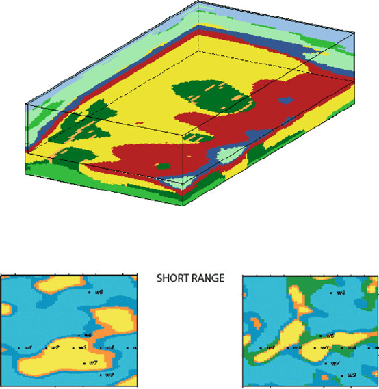
Fig. 8.12 Testing the variogram range influence on the reefal complex described in Fig. 8.7. The
figure shows a plan view of the reef using variograms with short ranges. Compare with Fig. 8.9 in
which the same plan was simulated with a long range
Fig.8.11 Simulation offractures onlyaffectingonefacieswithinthePennsylvanianalgal mounds
Petroleum Applications of the Plurigaussian Approach 133
Testing the Impact of the Rock-Type Rule
Normando et al. (2005) tested the effect of sli ghtly changing the rock-type rule on
the connec ti vit y of the reservoir whi le fixing the other parameters. In a study on
a mature Brazilian field with four facies, the authors showed permuting the
position of two of the facies in the rock-type rule led to significant changes in
the connectivity in sim ulated reservoirs obtained using the two diff erent rules
(Table 8.1).
Handling Heterotopic Data
The aim of the project between IFP, Ecole des Mines de Paris and the Italian oil
company, ENI, was totackle the problem of simultaneouslysimulating sedimentary
facies and diagenes is index in a reservoir deposited in a clastic fluvial environment.
Four sedimentary facies were defined from cores and logs of 15 wells. In addition
four diagenetic indices were identified from thin section analyses for some of the
wells. As the two properties are not known at the same locations, this dataset
is heterotopi c. This study gave us the opportunity to test different simulation
approaches to produce a reservoir model including the two properties, and to
Table 8.1 Percentage of
connected volume in one zone
of the reservoir
Rock type P90 (%) P50 (%) P10 (%)
N
1152025
N
2273135
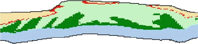
Fig. 8.13 Testing the variogram model. The simulation represents a cross section of the reef
complex described in Fig. 8.7. An exponential variogram model was used here. Compare with
Fig. 8.8 in which the same reef complex was simulated with a gaussian variogram
134 8 Case Studies and Practical Examples
identify the different characteristics of these methods. Th ree different approaches
were used to simulate the sedimentary facies and the diagenetic
l
Nested truncated gaussian simulations
l
Classical plurigaussian simulations (PGS)
l
Bi-plurigaussian simulations (Bi-PGS)
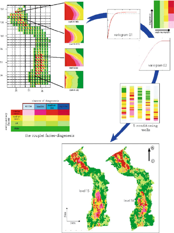
In the workflow for the nested simulations, the steps are performed sequentially:
first a classical plurigaussian simulation of sedimentary facies, using a vertical pro-
portion matrix in terms of sedimentary facies (Fig. 8.14); second, for each sedi-
mentary facies, a classical plurigaussian simulation of the diagenesis index,
and third the reconstitution of the final information using logical rules to combine
the different realizations (Fig. 8.15). The simulation parameters are specific to each
property, sedimentary facies and diagenesis index. This method makes it possible
to separate the constraints for each simulated property in terms of conditioning
wells and parameters. The diagenetic property is independent from one cell to
another, if the sedimentary facies change between these cells. The disadvantage is
that it will not be possible to use any correlations found between the sedimentation
and the diagenesis.
The classical plurigaussian simulation method (PGS) can be used direct ly if the
two indicators variable are combined into one single global indicator variable,
called the facies-diagenesis variable. In that case only the wells where both types
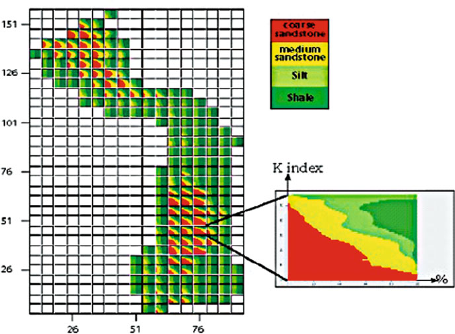
Fig. 8.14 Matrix of percentage for the sedimentary facies
Petroleum Applications of the Plurigaussian Approach 135
of informat ion, sedimentary facies and diagenesis index, are defined can be used for
the conditioning.
A single simulationwhere eachGaussian functionis associatedwithoneindicator
variable, (here G1 is related to the sedimentation and G2 is related to the diagenesis)
is carried out globally. A correlation coefficient between the two Gaussian functions
could be usedto takeaccountof a relationshipbetweensedimentationand diagenesis
(Fig. 8.16). This approach is in fact a short-cut to combine in one simulation two
mono-truncated Gaussian simulations. Thus the continuityin the diagenesis property
through the facies is respected by construction.
Fig. 8.17 illustrates the main differences between the three simulation methods.
The bi-plurigaussiansimulation (Bi-PGS) model has been also used as it provides
a sound basis for bivariate categorical simulation. In this approach, each physical
process is associated with a complete PGS. The two vertical proportion matrices
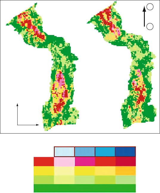
level 30
5 km
5 km
level 15
N
NO DIA low DIA high DIA
classes of diagenesis
sed imentary
facies
coarse
sands
medium
sands
silt
shale
medium
DIA
S
Fig. 8.15 Two levels in the reservoir model using nested truncated Gaussian simulations
136 8 Case Studies and Practical Examples
are linked through the conditional probabilities between the two indicators. The
advantage of this approach is that all the data are taken into account during the
conditioning, even the ones where only one indicator is available (Fig. 8.17).
Fig. 8.16 Workflow and parameters for plurigaussian simulation
Petroleum Applications of the Plurigaussian Approach 137
Mining Applications of the Plurigaussian Approach
In this section we present two applications of plurigaussian simulations to mining
projects. The first was developed in answer to a question by the French uranium
mining company, Areva: Is the plurigaussian approach suitable for reproducing the
characteristics of roll-front uranium deposits? As these deposits are formed in
permeable sandstone, the method is a natural extension of the techniques in the
oilindustry. The second case-study is anapplication to a porphyry copper deposit in
Chile, that is, in a non-sedimentary environment.
Roll-Front Uranium Deposit
In this application, we are interested in a roll-front uranium deposit and its exploi-
tation by in-situ leaching. The dataset comes from the Muyumkum deposit in the
South Khazakstan (Fontaine and Beucher 2006). Roll-front uranium deposits are
formed in permeable sandstone. The uranium is located at the interface between
oxidizing and reducing conditions.
The in-situ leaching technique consists of circulating oxidising and acid or
alkaline solutions in the mineralised area via injection wells to dissolve the uranium
selectively. As a consequence, there are two issues: on the one hand, to delimit the
areas where the uranium grade is above a given threshold and on the other hand to
reproduce the distribution of the hydrodynamic parameters to mimic the fluid flows
for the in-situ leaching.
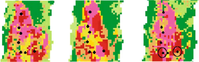
Fig. 8.17 Comparing the three approaches. The nested simulation (left) there is no con-
tinuity (correlation ) in the diagenesis variable. In the Bi-PGS simulation (centre) all data are
used and there is continuity in the diagenesis. In contrast the wells where there was no
diaenesis data were not used the PGS (right) and so the wells with circles a round them are
not respected
138 8 Case Studies and Practical Examples
First Issue
As the hydrodynamic parameter distribution depends mainly on the geological
characteristics, this constitutes the first step of the study. In the example, the facies
have been grouped in three classes from silt to medium and coarse grained sands.
Moreover the sands have been split into non-oxidized and oxidized facies. So,
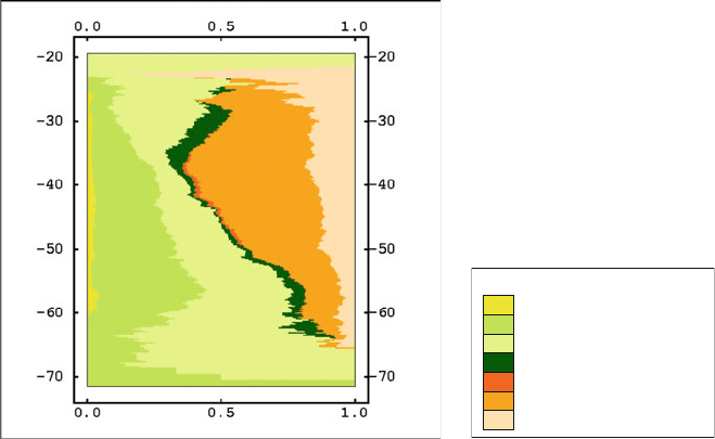
seven types were defined. The spatial distribution of the proportions (see vertical
proportion curves, Fig. 8.18, and vertical proportion matrix, Fig. 8.19) shows that
the oxidized types are predominantly in the south east which is correlated to the
origin of the oxidizing fluids. Vertically, these facies are more abundant in
the upper part of the deposit. The shale facies has almost the same proportion in
the whole domain.
As these seven types result from two processes, two underlying Gaussians
are used. The first one gives the granulometric evolution from coarse sand to silt
and the second one separates oxidized and non oxidized types. The shapes of the
experimental variograms confirm the choice of the lithotype rule. The fits of the
oxidized facies is presented in the figure.
Giving this lithotype rule, the fit of shale type gives the parameters for the first
gaussian random function. Then the second one is chosen by fitting the other
experimental indicator variograms. The result is presented for the oxidized facies
in Fig. 8.20. A vertical E-W cross-section in a conditional simulation (Fig. 8.21)
Lithotypes
coarse sand
medium sand
fine sand +silt
shale
coarse sand oxy
medium sand oxy
fine sand oxy
Fig. 8.18 Vertical proportion curves (VPC)
Mining Applications of the Plurigaussian Approach 139