Altan T. Metal Forming Handbook
Подождите немного. Документ загружается.

6.7.2Die and punch design
Dies are subjected to high degrees of internal pressure which can quick-
ly lead to die failure using single ring extrusion containers manufac-
tured with die steels available today. The extremely high stresses, pre-
sent on the internal die wall of the extrusion container (cf. Sect. 6.5.1)
can be reduced by pre-stressing (shrink-fit) the container with one or
more shrink rings. Punches are subjected initially to pressure and then
additionally, depending on the process, to bending stress as a result of
off-center loads. Less frequently, the possibility of punch buckling must
be taken into consideration. The calculation methods outlined here for
dies and punches are described in detail in VDI Guidelines 3176, VDI
3186 and ICFG Doc. No. 5/82.
491
Die design
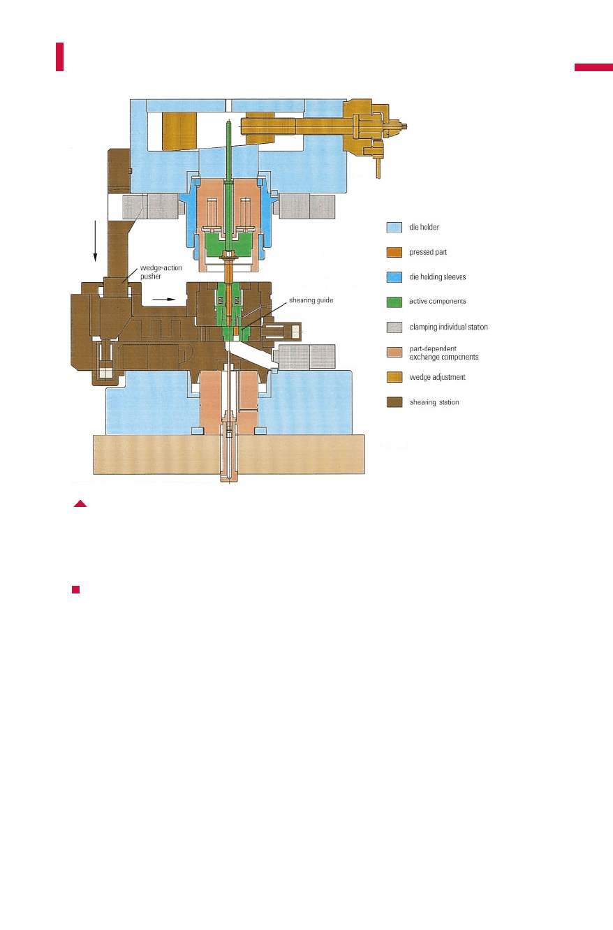
Fig. 6.7.5 Shearing die with wedge-action pusher, holding sleeve hydraulically clamped
Metal Forming Handbook / Schuler (c) Springer-Verlag Berlin Heidelberg 1998
Die design
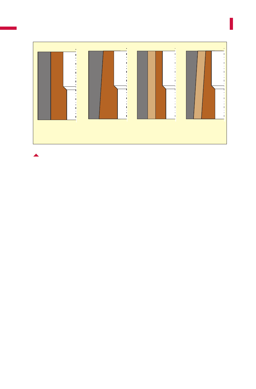
In Fig.6.7.6,various shrink ring designs are illustrated. Cylindrical
shrink fits are simpler to produce, but can only be used up to interfer-
ences which can be achieved by warm shrink fitting, in order to avoid
cold welds during assembly.
Tapered shrink fits permit simpler, scratch-free disassembly. A draw-
back of this method are the high production costs. The tapered shrink
fit exhibits different levels of radial pre-stress, which can lead in case of
very long containers to dimensional differences on the forged part.
Usual taper angles are 0.5 and 1°; if the height to diameter ratio of the
container is below 0.8, taper angles of 2 to 3°are used in order to avoid
disassembly of the shrink rings during part ejection. Analytic approxi-
mate operations are based on the method by LAMÉ and were published
by Adler/Walter. These assume an ideal loading situation where an infi-
nitely long thick-walled cylinder is subjected to a constant hydrostatic
pressure over its entire length. Using Tresca’s yield condition, which can
be applied in this case, the stress distribution can be calculated. It is
found that the maximum values are at the internal wall of the contain-
er and correspond approximately to the value of the internal pressure p
i
,
492
Solid forming (Forging)
Fig. 6.7.6 Shrink fits with single and double rings – each with cylindrical and tapered fits
cylindrical shrink
fit surface
cylindrical shrink
fit surface
tapered shrink
fit surface
tapered shrink
fit surface
single shrink ring double shrink ring
Metal Forming Handbook / Schuler (c) Springer-Verlag Berlin Heidelberg 1998

for radial stress s
r
and tangential stress s
t
(Fig. 6.7.7, left). The internal
pressure can therefore, due to
amount to no more than , for the effective stress s
v
= R
p0.2
. Thus,
for material values of R
p0.2
= 2,000N/mm
2
, maximum pressure levels
of 1,000 N/mm
2
are permissible. If, in the case of thick-walled pipes
subjected to internal pressure, the effective stress exceeds the yield
strength of a material with sufficient toughness, then plastic flow
occurs at the inside wall of the container. If the ultimate strength is
reached in containers or inserts from brittle materials, cracks occur.
As a result of adding compressive stress, the tangential stress and
thus also the effective stress status at the inside wall of the extrusion
container (or insert) are reduced (Fig. 6.7.7center, right).
The radial pre-stress is generated by means of shrink rings. A shrink
ring has an internal diameter that is smaller than the outer diameter of
the corresponding inner ring by a selected dimension (interference). By
maintaining the outer diameter unchanged, the permissible internal
pressure can be increased by up to 100% as a result of the shrink ring
compared to a container without a shrink ring. For a given permissible
internal pressure, the outside diameter of the container, using shrink
493
Die design
Fig. 6.7.7 Theoretical stress distribution in a thick-walled single-piece hollow cylinder
(left),
a two-part
(center)
and three-part
(right)
shrink fit design (red: without internal
pressure, blue: with internal pressure)
2.5
2.0
1.5
1.0
0.5
0
-0.5
-1.0
dD
vi
/p
ti
/p
ri
/p
p
i
a
b
c
p
i
r
t
p
i
t
r
+
-
σσσ
vrti
p=+=2
R
p02
2
.
Metal Forming Handbook / Schuler (c) Springer-Verlag Berlin Heidelberg 1998

rings, can be reduced by about 60% (Table 6.7.2). In multiple-station
forming machines this results in a substantial reduction of die diame-
ters, the distances between stations, the dimensions of the die holder
and thus also the machine bed size.
Carbide cannot be subject to tensile stresses. Therefore, when using
dies or inserts from carbide, the extrusion container must be pre-
stressed in such a way that no tangential tensile stress occurs under
internal pressure. Accordingly, the interference dimensions are consid-
erably higher than those used for tool steels. Guidelines also have been
established for the calculation of axial pre-stress levels; in the thin, ring-
shaped lateral split, surface pressures of 700 to 1,000 N/mm
2
are as-
sumed as guideline values.
In extrusion dies, the actual stress conditions differ from the ideal
assumptions made here, however. The extrusion containers have a
finite length, a limited and possibly eccentric pressure area, no uniform
internal pressure exists, and the containers have often off-center die
openings. Realistic conditions in the configuration of shrink fit assem-
blies can be determined by using discrete approximation techniques,
for example the finite element method (FEM). For practice-oriented
application, various calculations have been conducted by making a
parametric study using FEM. These results have been made accessible
for practical application in the form of Nomograms (VDI 3176, ICFG
Doc. 5/82) and corresponding computer programs.
Punch design
Extrusion punches are subjected to an axial force with an average com-
pressive stress. They are calculated as follows:
494
Solid forming (Forging)
Table 6.7.2: Increase of the allowable internal pressure p
i zul.
or reduction of the outside diameter d
a
through single and double shrink rings
Characteristic value Press container
without shrink ring with single shrink ring with double shrink ring
p
i zul.
[N/mm
2
] 690 1,160 1,395
d
a
[mm] with d
i
= 20 mm 100 40 36.4
p
F
A
St
St
St
=
Metal Forming Handbook / Schuler (c) Springer-Verlag Berlin Heidelberg 1998
The off-center applied force causes additional bending stresses. The
overall stress in the punch then amounts to:
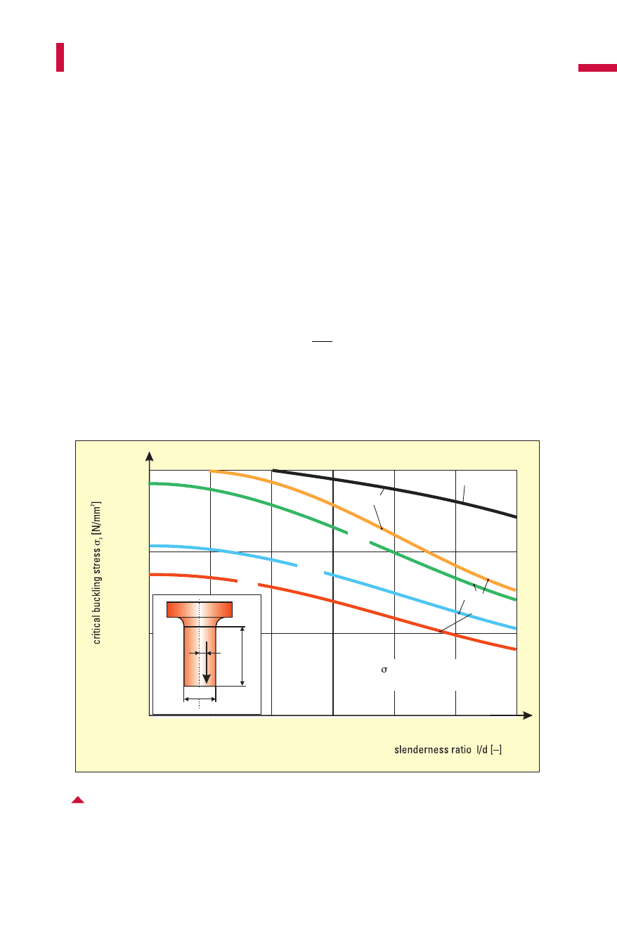
whereby d [mm] is the punch diameter and e [mm] the off-center posi-
tion of force application. Values for critical buckling stress are provided
in Fig.6.7.8. With backward cup extrusion, the eccentricity generally
amounts to e/d = 0.01 to 0.02. The calculated punch stress is compared
to the compressive yield strength of the punch material in its hardened
state.
The counterpunch is subjected to an average compressive stress of
during backward cup extrusion.
495
Die design
Fig. 6.7.8Critical buckling stress in function of the slenderness ratio (l/d) of a punch made of
high-speed steel: 1 forward rod extrusion; 2 backward cup extrusion; d punch dia-
meter;e off-center position of force application; l (free) punch length
1,000
2,000
3,000
024681012
0.1
0.05
0.01
e/d=0
forward
rodextrusion
backward
cupextrusion
md
=3,000N/mm
E=225,000N/mm
2
2
d
F
U
e
l
σ
Stges St
ped=+⋅
()
18/
p
F
A
G
St
=
0
Metal Forming Handbook / Schuler (c) Springer-Verlag Berlin Heidelberg 1998

6.7.3Die and punch materials
Materials used for cold and warm forming are required to have high
strength, high toughness and high hardness. For an economical die life,
extremely good wear and tempering resistance are necessary. Die mate-
rials should be chosen, where possible, to ensure good machinability,
and as a result, low manufacturing costs (cf. Sect. 4.1.3).
All these requirements cannot be fulfilled simultaneously by each
type of tool steel. The characteristics wear resistance and toughness, for
example, show opposing tendencies. The materials 55NiCrMoV6
(1.2713), 57NiCrMoV7 (1.2714) and X3NiCoMoTi1895 (1.2709) are
extremely tough and are used for shrink rings and inserts which are
subjected to high levels of elongation. Their wear characteristics, in
496
Solid forming (Forging)
Table 6.7.3: Survey of the most frequently used cold, warm and hot forging tool steels
Die materials I / Cold forging tool steels / Active components
Material No. DIN ANSI JIS Composition in %
to DIN Germany USA Japan C Si Mn P S Co Cr Mo Ni V W Ti
1.2363 X100CrMoV51 A2 SKD11 1.00 0.30 0.55 0.03 0.03 – 5.00 1.10 – 0.20 – –
1.2369 81M0CrV4216 0.81 0.25 0.35 – – – 4.00 4.20 – 1.00 – –
1.2379 X155CrVMo12 1 D2 SKD11 1.55 0.30 0.35 0.03 0.03 – 12 0.70 – 1.00 – –
1.2709 X3NiCoMoTi1895 0.03 0.10 0.15 0.01 0.01 9.25 0.25 5.00 18 – – –
1.27131. NiCrMo55NiCrMoV6 6F2 0.55 0.30 0.60 0.03 0.03 – 0.70 0.30 1.70 0,10 – –
1.2714 57NiCrMoV7 SKT4 0.58 0.30 0.70 0.03 0.03 – 1.00 0.50 1.70 0.10 – -
1.2767 X45NiCrMo4 6F7 0.45 0.25 0.30 0.03 0.03 – 1.35 0.25 4.00 – – –
1.3207HSS S10-4-3-10 T42 SKH57
1.3343 S-6-5-2 M2 SKH51 0.90 0.45 0.40 0.03 0.03 – 4.15 5.00 – 1.85 6.35 –
1.3344 S-6-10-2 M3/2 1.20 0.45 0.40 0.03 0.03 – 4.15 5.00 – 3.00 6.35 –
Die materials I / Hot-warm forging tool steels / Active components
Material No. DIN ANSI JIS Composition in %
to DIN Germany USA Japan C Si Mn P S Co Cr Mo Ni V W Ti
1.27131. NiCrMo55NiCrMoV6 6F2 SKT4 0.55 0.30 0.60 0.03 0.03 – 0.70 0.30 1.70 0.10 – –
1.2714 57NiCrMoV7 SKT4 0.58 0.30 0.70 0.03 0.03 – 1.00 0.50 1.70 0.10 – –
1.23432. CrNiMoVX32CrMoV51 0.38 1.00 0.40 0.03 0.03 – 5.30 1.10 – 0.40 – –
1.2344 X40CrMoV51 H13
H11 SKD6
SKD61 0.40 1.00 0.40 0.03 0.03 – 5.30 1.40 – 1.00 – –
1.2365 X32CrMoV33 H10 0.32 0.30 0.30 0.03 0.03 – 0.30 2.80 ––––
1.2367 X40CrMoV53 SKD7 0.30 0.20 0.30 0.03 0.03 – 2.40 – – – 4.30 –
1.26063. WCrV X40CrMoW51
1.2622 X60WCrCoV93 SKH51
SKD62
SKT4
Metal Forming Handbook / Schuler (c) Springer-Verlag Berlin Heidelberg 1998

contrast, are not quite as favorable. The high-speed steel S10-4-3-10
(1.3207) offers outstanding wear characteristics, but tends to be more
brittle. The materials X155CrVMo121 (1.2379) and S-6-5-2/S-6-10-2
(1.3343/44) represent a compromise concerning wear and toughness
characteristics: Their tempering resistance can also be considered to be
very good at 550°C. The most important criterion to be considered
when selecting a tool material is the type and extent of load, followed
by the layout and geometry of the die.
Table 6.7.3 provides a summary of the most commonly used tool
materials for cold and warm forming. The table also specifies the desig-
nations of comparable steels from the USA or Japan and their composi-
tions. Table 6.7.4 describes the heat treatment, i.e. the annealing tem-
497
Die design
Table 6.7.4: Heat treatment of cold, warm and hot forging tool steels
Die material II / Cold forging tool steels / Active components
No. Heat treatment (
°C) Hardness Cooling Application/hardness (HRC/N/mm
2
)
AnnealingHardening
Quenching
medium
Quenching
medium
Tempering (customary)Water
1.2363 800-840 930-970 Ö,WB 400 180-400 60 +/–1 blanking/punching dies
1.2369 800-840 1,070-1,100Ö,WB 450-550 550 61 +/–1 punches, blanking/punching dies
1.2379 840-860 1,040-1,080Ö,L,WB 400 180-250 60 +/–1 punches, dies
1.2709 840 480 L – 55 shrink ring
1.2713 650-700 830-870 Ö 300-650 45 +/–1 P,Ö,(W) shrink/intermediate ring and
1.2714 650-700 860-900 L 300-650 45 +/–1 P,Ö,(W) pressure pin (53+/-1 HRC, 1,150 N/mm
2
)
1.2767 610-630 840-870 W,Ö,L 160-250 54 +/–1 punch, mandrel, one piece press container
1.3343 1,100-900 790-820 Ö,L,WB 550 540-560 62 +/–1 punch, die (insert), press container and
1.3344 1,100-900 770-820 Ö,L,WB 550 550-570 62 +/–1 counterpunch, mandrel
Die material II / Hot, warm forging tool steels / Active components
No. Heat treatment (
°C) Hardness Cooling Application/hardness
AnnealingHardening Tempering (customary)
HRC
1.2713 650-700 830-870 Ö 300-650 42 +2 P,Ö,(W) shrink/intermediate ring and
1.2714 650-700 860-900 L 300-650 42 +2 P,Ö,(W) pressure pin (52+2 HRC, 1,150 N/mm
2
)
1.2343 750-800 1,000-1,040L,Ö,WB 500-550 550-650 50 +2 W,P,Ö die (insert), shrink ring (45+/–1 HRC)
1.2344 750-800 1,020-1,060L,Ö,WB 500-550 550-650 50 +2 P,Ö mandrel and counterpunch
1.2365 750-800 1,020-1,060Ö,WB 500-550 500-670 50 +2 (W),L,P,Ö die (insert), punch and
1.2367 750-800 1,060-1,100L,Ö,WB 500-550 600-700 54 +2 (W),L,P,Ö counterpunch
1.2606 750-790 1,020-1,050Ö,L,WB 500-550 550-650 W,L,P,Ö
1.2622 760-800 1,150-1,200Ö,WB 500-550 500-650 56 +2 L,Ö blanking die
W = water WB = water bath
L = air
P = compressed air
Ö = oil
Metal Forming Handbook / Schuler (c) Springer-Verlag Berlin Heidelberg 1998

perature, the hardening temperature, the quenching medium and the
tempering temperatures. The levels of hardness generally required for
dies used in cold forming applications are also given. Table6.7.5
describes the characteristics of wear, toughness, machinability and
grinding using a 10-point scale, whereby a high number indicates espe-
cially good capability. The tables make no claim to completeness, but
present a substantially reduced number of actually required tool steels
in following the principles of optimised and reduced inventory.
The most frequent tool material used for cold forging is high-speed
steel, while for warm forging temperature-resistant tool steel is used.
498
Solid forming (Forging)
Table 6.7.5: Properties of cold, warm and hot forging tool steels
Die materials III / Cold forging tool steel / Active components
Characteristics Remark
VZBS
7687
7/8 5
8 4 4 4 12 % Cr-steel
5 9 5 7 special steel
21068
41068
9245
9445
10334
2 10 6 8 44 HRC 1,400 -1,480 N/mm
2
52 HRC 1,800 - 1,900 N/mm
2
5 8 50 HRC 1,700 - 1,800 N/mm
2
5 8 8 8 surface welding Capilla 521 for erosive machining
surface welding Capilla 5200 for machining
4
8 8 8 50 HRC 1,700 - 1,800 N/mm
2
5 7 8 8 54 HRC 1,925 - 2,050 N/mm
2
56 HRC 2,050 - 2,200 N/mm
2
V = wear resistance
Z = toughness
B = machinability
S = grindability
No.
1.2363
1.2369
1.2379
1.2709
1.2713
1.2714
1.2767
1.3343
1.3344
No.
1.2713
1.2714
1.2343
1.2344
1.2365
1.2367
1.2606
1.2622
Die materials III / Hot, warm forging tool steel / Active components
VZBS
Characteristics Remark
Metal Forming Handbook / Schuler (c) Springer-Verlag Berlin Heidelberg 1998

Powder metal-manufactured high-speed steels demonstrate very uni-
form carbide distribution and are segregation-free. This results in
improved toughness properties and extremely high compressive
strength. If a larger wear resistance is required, for example for forward
rod extrusion or ironing dies, for large-production series carbides are
also used. The carbide types used comprise tungsten carbide as a phase
in a cobalt matrix. The cobalt content which determines the character-
istics of the carbide, lies between 15 and 30%. With a rising tungsten
carbide content, hardness, compressive strength and wear resistance all
increase. However, at the same time toughness, notch impact strength,
bending and buckling resistance are reduced. The grain size exerts an
influence here: fine-grained carbides are unsuitable as a result of poor
toughness characteristics. Table 6.7.6 provides a summary of the
mechanical characteristics of carbides. The strength values apply to sta-
tic loads and must be reduced by 50% for stress cycles greater than 10
6
.
Tool steels for warm forming
The materials X40CrMoV53 (1.2367), X38CrMoV51 (1.2343), X40-
CrMoV51 (1.2344) and X60WCrCoV93 (1.2622) are currently used for
warm forming and in conjunction with the water cooling method gen-
erally applied today; In the case of shrink rings, 55NiCrMoV6
(1.2713)/57NiCrMoV7 (1.2714) or X38CrMoV51 (1.2343)/X40CrMoV-
51 (1.2344) can be used. Due to their low thermal shock resistance, car-
bides, high-speed steels and cold forming tool steel 81MoCrV4216
(1.2369) are only suitable when using water-free cooling methods
which were common in the past. On closer examination, it becomes
clear that materials for warm forging are generally those used in the
classical field of hot forging. Special materials for warm forging, which
are capable of withstanding relatively high pressure levels and relative-
ly high temperatures simultaneously, have not yet been developed for
implementation in series production. Developments of die materials
for warm forming are moving in the following directions:
Compared to hot forging tool steels, high-speed steels already exhib-
it good wear and heat resistance properties as well as improved temper-
ing resistance. By a gradual reduction of the carbon content, attempts
have been made to achieve a further improvement in thermal shock
resistance of high-speed steels. With simultaneous deterioration of the
wear and heat resistance, however, the thermal shock resistance level
499
Die design
Metal Forming Handbook / Schuler (c) Springer-Verlag Berlin Heidelberg 1998

was far below that of hot forming tool steels. In view of the successful
implementation of environmentally friendly water-soluble lubricants,
the factor thermal shock resistance is expected to continue to be a sub-
ject of particular interest.
Thus, investigations are concentrated on tool steels which are
derived from hot forming tool steels, i.e. those which have a relatively
low carbon content. These tool steels demonstrate superior wear and
heat resistance properties as well as very good thermal shock resistance.
A number of different die materials are being developed concurrently,
for example using nickel-based alloys (Inconell 718), which have
already produced good results in bar extrusion (temperatures 1,150 °C,
pressures of 900 to 1,100 N/mm
2
) and isotherm forging applications.
Die coatings (VDI 3198)
The cost-effectiveness of cold forging processes depends largely on the
tool costs and accordingly on the achievable service life of dies. Die
wear influences the dimensional stability and surface quality of the pro-
duced workpieces. There are two main types of wear resistant coatings
considered for use in forging technology. Coatings, for example using
adding-on processes such as CVD or PVD processes, and coatings
obtained through reaction layers such as nitriding and ion implanta-
tion. Processes which have proven successful for cold forming dies
include the CVD and PVD techniques, which permit service life to be
more than doubled (cf. Sect. 4.1.3).
An essential prerequisite for a successful coating is good adhesion
between the coating material and the substrate, whose hardness and
compressive strength must provide adequate support. High-speed steels,
500
Solid forming (Forging)
Table 6.7.6: Mechanical properties of carbides
Carbide types E-modulus Ultimate strength
Co content Density Hardness Compressive strength Bending strength
% by weight g/cm
3
HV N/mm
2
N/mm
2
N/mm
2
15 14.0 1,150 530,000 4,000 2,400
20 13.5 1,050 480,000 3,800 2,600
25 13.1 900 450,000 3,300 2,600
30 12.7 800 420,000 3,100 2,700
Metal Forming Handbook / Schuler (c) Springer-Verlag Berlin Heidelberg 1998