Altan T. Metal Forming Handbook
Подождите немного. Документ загружается.


For cold forming processes, the gripper units are mounted on clamp-
ing rails which are fixed in turn on a base rail(Fig. 6.6.1).When reset-
ting for producing a different part, all that has to be exchanged are the
clamping rails including the pre-set grippers. The front grippers are
equipped with proximity switches to monitor part transfer.
Parts with a higher L/D ratio (approx. 3 to 8) must be transferred
between stations by a 3D transfer. This involves the use of an addition-
al horizontal pusher which moves the part together with its retainer
into a position from where it can be raised vertically. Here, too, the lev-
el of the base plate on which the parts are positioned is located below
the transport plane. Shaft-shaped parts with a billet L/D ratio of > 6 can
also be moved into the uplift position using special devices such as
rotating sleeve retainers.
In warm forming, the loading station has the additional function of
segregating parts which either have not been fed in correct synchro-
nization with the press, or which have an incorrect temperature. To
allow these parts to be ejected, an opening is released in the base plate
of the loading station through which the parts drop down into a chute
for removal.
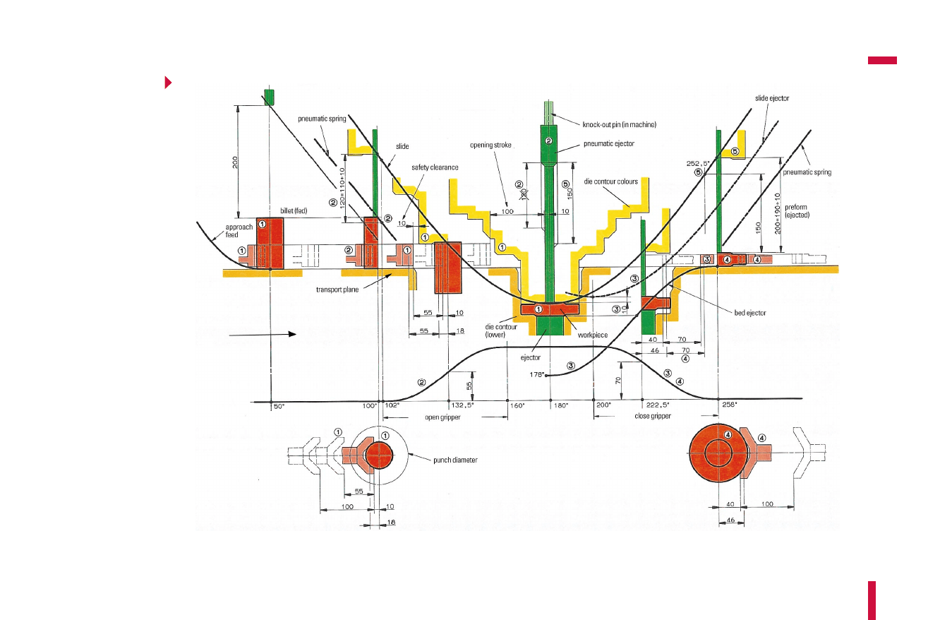
6.6.2Transfer study
Before conducting a transfer study, data on the kinematics of the slide
movement must be available in the form of a time-displacement dia-
gram. The stroke is defined based on the range of parts, the required
forming process and the die layout. The slide curve is given by the stroke
height and press kinematics (eccentric drive, knuckle-joint drive, modi-
fied knuckle-joint drive) (cf.Fig.3.2.3). The slide curve, whose bottom
dead center is at 180°, can only be displaced vertically for transfer study.
The ejector stroke is determined by the range of parts being processed
and the respective position of the forming stations in the die. The
largest necessary ejector stroke is equal to the sum of the inlay depth of
the part in the die and the part length. The ejector stroke can be
achieved by means of a mechanical and an additional pneumatic dis-
placement. The stroke covered mechanically must eject the part, which
is stuck in the tool as a result of elastic deflection of the container. In
addition, the pneumatically generated displacement is able to raise the
481
Part transfer
Metal Forming Handbook / Schuler (c) Springer-Verlag Berlin Heidelberg 1998

part. Our present example has a mechanical ejector curve with a stroke
of 200mm which is travelled through at 80°crank angle: In this case,
no pneumatic ejector is required. The starting point for the ejector
curve can be optionally selected, allowing the curve in the diagram
(Fig. 6.6.2)to be displaced horizontally. The slope of the ejector curve
can be configured in such a way that it corresponds approximately to
the linear portion of the slide curve.
Starting with the transverse movement of the connecting rod, the
slide ejector curve is generated by the corresponding kinematic
(Fig. 6.6.2, dashed line). For the transfer study, this curve can be dis-
placed only vertically.
The curve of the pneumatic ejector, whose actual distance from the
slide curve must be determined with the transfer study, runs parallel to
the slide curve (Fig. 6.6.2, broken line).The slide ejector acts mechani-
cally briefly after the bottom dead center and can be operated pneu-
matically after that.
In addition to these main press motions, in universal transfer devices
the curves for opening and shutting the grippers are also significant. The
opening and closing times can normally be adjusted within certain lim-
its, e.g. within a 30°range, making the curves horizontally displaceable
in the transfer study. The opening stroke is determined by the required
diameter of the upper die (Fig. 6.6.2, opening stroke 100 mm). Where
mostly slender punches are used, this stroke is smaller than for female
dies used on the side of the slide, for example when producing long rod-
shaped parts or parts in closing devices. Depending on the opening
stroke, these movements require a smaller (approx. 30°for around
40 mm) or a larger (approx. 60°for around 100 mm) crank angle range.
Through the forward and reverse movement, lateral transportation
takes place. Forward motion can be initiated as soon as the grippers
engage the part, and must have been completed before the grippers
open, i. e. the upper die elements make contact with the transported
part. The forward and return motions require a crank angle of approx.
80 to 100°. The return motion takes place during the infeed and press-
ing cycles.
Transport studies of 3D transfer devices involve a lift-up motion in
addition to the movements previously described. This motion starts
briefly after the ejector movement and after the closing of the grippers.
It ends with the lowering motion which should have been completed
482
Solid forming (Forging)
Metal Forming Handbook / Schuler (c) Springer-Verlag Berlin Heidelberg 1998
483
Part transfer
Fig. 6.6.2 Two-dimensional transfer study:
1 define opening starting point; 2 determine pneumatic spring travel for fed part;
3 define shortening of ejector bolt in the machine and starting point of
ejector in bed; 4 define closing end point;
5 determine pneumatic spring travel for ejected part
Metal Forming Handbook / Schuler (c) Springer-Verlag Berlin Heidelberg 1998

just before the opening of the grippers. Here, too, depending on the lift-
up motion, a greater or smaller crank angle range may be required. A
lift-up motion of around 100mm can require a crank angle of around
60°. All the transport motions of the press and transfer device are limit-
ed by maximum allowable acceleration levels, and must be separately
designed for each individual case under consideration.
484
Solid forming (Forging)
Metal Forming Handbook / Schuler (c) Springer-Verlag Berlin Heidelberg 1998

6Solid forming (Forging)
6.7Die design
In industrial practice, extrusion or cold forging dies are frequently sub-
ject to parametric designs and adaptations, making the configuration of
the punches and dies of central importance. Less frequently, for exam-
ple where a new press is used, questions related to die holder design and
spare and active die sets must be addressed. Modern cold and warm forg-
ing dies have a multiple-station configuration. Most of the main forging
operations are completed within one to three stations. However, using
four or even five-station die sets it is possible to execute other sizing,
piercing and trimming operations in one and the same processing step.
Thus, it is possible to approach the objective of net shape or near net
shape production, and to reduce the transport and processing costs
involved in an additional pass through the press.
Figure 6.7.1illustrates the basic schematic layout of a modern multi-
ple-station die for a universal press. An intermediate plate is mounted
on the press bed and distributes the press force in the form of a pressure
cone which increases in size as it acts on the press bed. The intermediate
plate is equipped with recesses for connecting the shafts of the transfer
device clamping boxes, and is able to accommodate sensors for press
force measurement or roller brackets for die set changeover. Hydraulic
die clamps for complete die change operations can also be located on
the intermediate plate.
The die base plate houses the die holding sleeves. As demonstrated in
the example, this plate can also hold hydraulic closing devices and
scrap chutes. However, where these are used, the overall height of the
plate must be configured to be higher. The dies themselves can be
mounted in a retainer block which reaches over the entire width of the
Metal Forming Handbook / Schuler (c) Springer-Verlag Berlin Heidelberg 1998
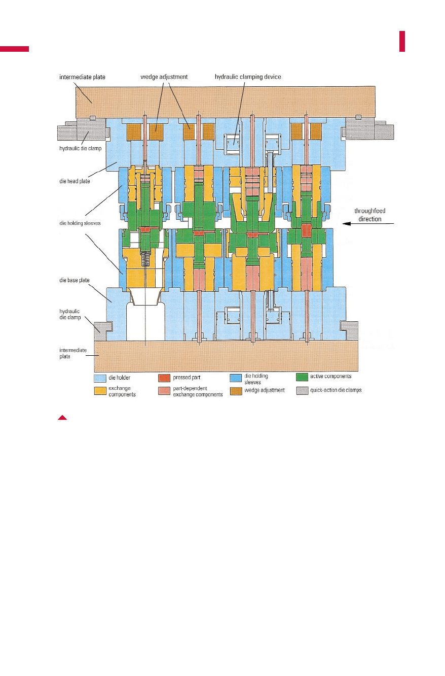
die. However, for warm forming and in some cases also for cold form-
ing, the use of single die holding sleeves is preferred. Thus, the thermal
expansion is absorbed in each individual die holder, independent of
other die stations. Using a suitable cooling device, it is possible to pre-
vent the motion of die block, as a result of thermal expansion, relative
to the die halves mounted on the slide.
In principle, the layout of the upper die is similar. However, addition-
al wedge adjustment devices (Fig.6.7.2)are located in the head plate.
These are used for individual height adjustment of the dies. The wedge
adjustment devices have an adjustment height of about 3 to 5mm.
486
Solid forming (Forging)
Fig. 6.7.1 Four-station die holder with hydraulic die clamping and closing system
in the second station
Metal Forming Handbook / Schuler (c) Springer-Verlag Berlin Heidelberg 1998
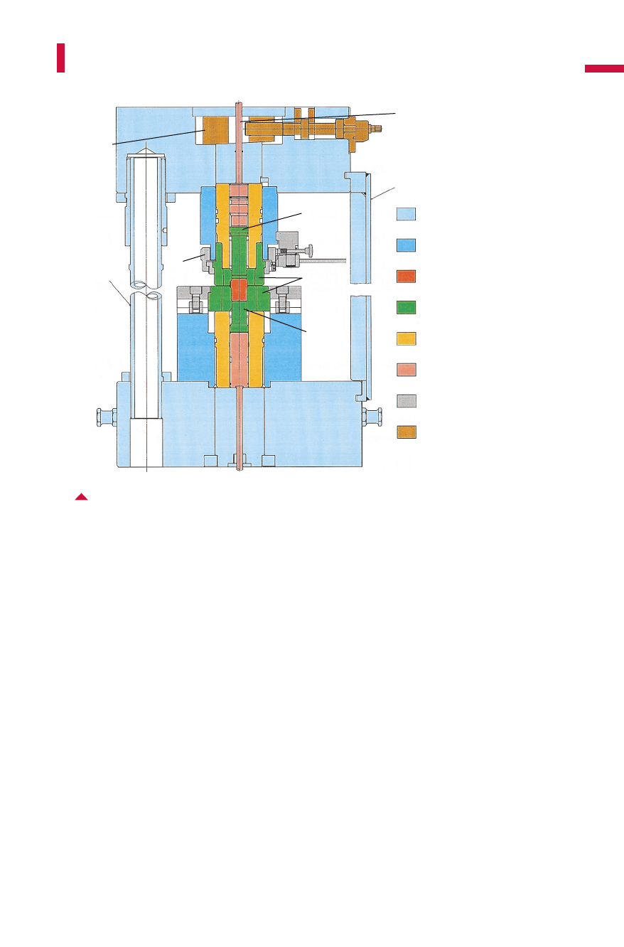
If no slide height adjustment is available in the press, the wedges must
then have a longer adjustment height of approx. 8 to 12mm in the indi-
vidual stations. Before actuating a wedge adjustment device, the clamp-
ing ring is released, thus allowing the downward motion of the dies. The
upper dies are relatively high, as they are designed to accommodate
pneumatically supported pads for workpiece transfer (Fig. 6.7.3).As a
result, reliable part transfer is ensured. Thus, higher effective stroking
rates and increased output can be obtained. The stroke of the pneumat-
ic ejectors is determined by means of a transfer study (cf. Sect. 6.6.2).
Active and exchange die components are located in the die holders.
The active die components contact the workpiece contour and are sub-
ject to wear. These must be reworked or replaced periodically. The
active die components include the containers, the die inserts, punches
and counterpunches, as well as for example stripper sleeves. The part-
dependent tooling must be exchanged together with the active die
487
Die design
Fig. 6.7.2 Section through a die holder with wedge adjustment
(auxiliary columns and transport straps are built in for die holder change)
die holder
die holding sleeves
pressed part
active components
exchange components
part-dependent
exchange components
acitve component clamping
wedge adjustment
transport strap
pneumatic pad
punch
clamping
ring
dies
counter-
punch
auxiliary
column
wedge
adjustment
Metal Forming Handbook / Schuler (c) Springer-Verlag Berlin Heidelberg 1998
components when setting up the press for a new product. Other uni-
versally used exchange tooling components remain in the holding
sleeves. The exchange tooling include mainly pressure plates, pressure
pins, spring elements and guide sleeves. For the structural design of
active and exchange components of die sets, please refer to the VDI
Guidelines 3176, 3186 Sheets 1 to 3.
6.7.1Die holders
The die holders hold both the active and exchange tooling compo-
nents. Their function is to ensure that the lower and upper die operate
as on-center as possible in relation to each other. The number of sta-
tions, the distance between stations and the holder sizes are generally
grouped together in standardized series. Table 6.7.1 illustrates a modu-
488
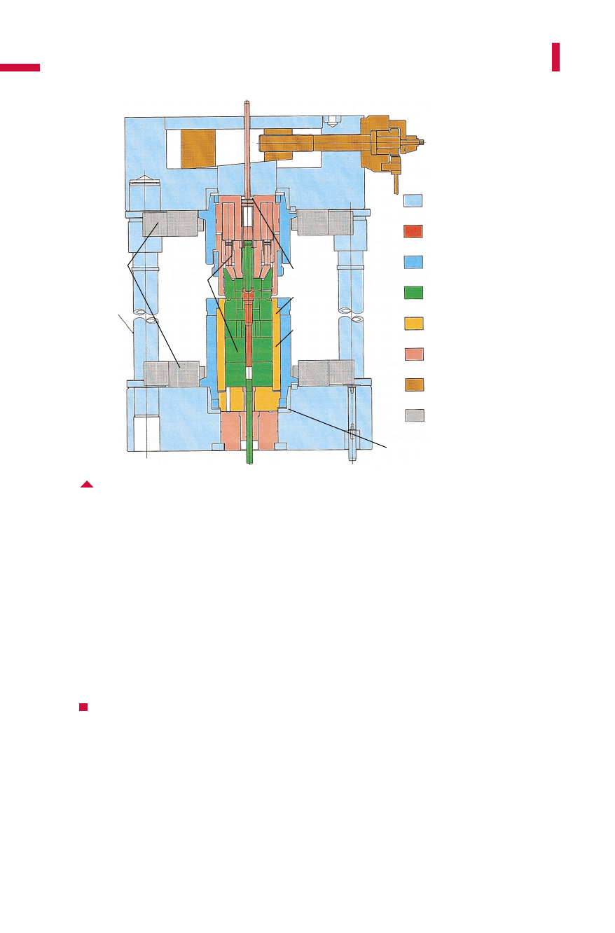
Solid forming (Forging)
Fig. 6.7.3 Section through a die holder with wedge adjustment and
hydraulic sleeve clamping
die holder
pressed part
die holding sleeves
active components
exchange components
part-dependent exchange
components
wedge adjustment
clamping individual station
active and
exchange
dies
auxiliary
column
intermediate
die sleeve
die holding
sleeve
pneumatic
pad
hydraulic
sleeve
clamping by
means of
wedge clamp
conical retainers
Metal Forming Handbook / Schuler (c) Springer-Verlag Berlin Heidelberg 1998

lar system of this type for a universal press design frequently used for
forming parts of approx. 0.1 to 15kg. Of course, other component and
die sizes can also be implemented.
The die change system is closely linked with the die holder design.
The range of parts to be produced and the individual batch sizes are the
main criteria that influence the die holder design and the layout of the
die changing system.
The complete die holder change, required when starting work on a
completely new part, involves moving the entire die holder out of the
machine to be replaced by a ready-prepared holder located in a pre-
scribed waiting position. The die head and base plate of the die holders
are hydraulically clamped (Fig.6.7.1).For moving in and out of the
press, the upper and lower part are moved together by means of
auxiliary columns and locked together with safety straps for transport
(Fig. 6.7.2). A third die holder can be assembled and set-up in the die
shop during the pressing or exchanging the die holders. For this
method of die holder exchange, parts of the gripper rails have to be
uncoupled, fixed on the die holder and removed together from the
press. Depending on the size of the holder, the exchange can take any-
where between 20 and 40min. These times include resetting of the
feeding station and, in the case of warm pressing, of the induction fur-
nace as well.
In exchanging the sleeves, the base and the head plate are left in the
press and the sleeves in the table and slide are replaced individually. For
this purpose, the base and head plate are fastened at the bed and slide.
They are equipped with conical centering rings (Fig.6.7.3and6.7.4).
489
Die design
Table 6.7.1: Modular system for possible die holder sizes (widths) (bold = frequently used sizes) for
number of and distance between stations
Number of stations Die holder widths with distances between stations in mm
200 250 300 350 400
2 400 500 600/750 700 800
3 600 750 900/1,000 1,050 1,200
4 800 1,000 1,200/1,250 1,400/1,500 1,600
5 1,000 1,250 1,500 1,850 2,000
6 1,200/1,250 1,500 –––
Metal Forming Handbook / Schuler (c) Springer-Verlag Berlin Heidelberg 1998
Each die holding sleeve is fastened by means of two to four hydraulic
wedge-type clamps (Fig.6.7.3).This design is used for large batch sizes
when the tools wear at very different rates in the individual stations
and have to be individually replaced. In this case, ready prepared die
holding sleeves are located in a prescribed loading position and can be
mounted into the die station by a die changing arm (cf. Fig. 3.4.5).It
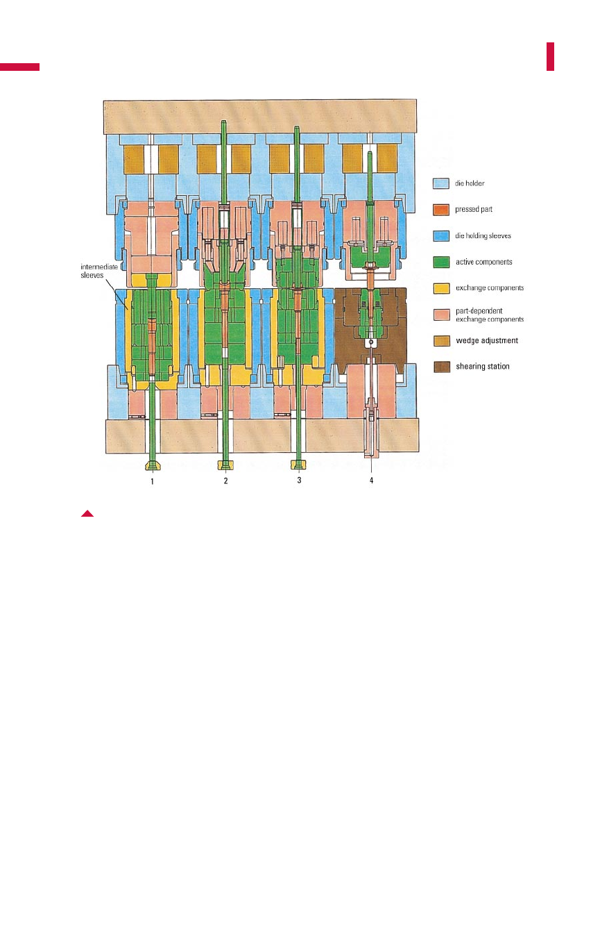
takes between 4 and 8 min to replace one sleeve. Figures 6.7.3and 6.7.4
illustrate the use of intermediate sleeves which can be assembled with
axial pre-stressing. Multiple-station forging permits subsequent opera-
tions to be executed in one processing step. As illustrated in Fig. 6.7.4
and 6.7.5,in the case of this specific die holder, the end of the extrud-
ed shaft is sheared to the required length by a wedge-action pusher die
in the fourth die station.
490
Solid forming (Forging)
Fig. 6.7.4 Four-station die holder with hydraulic sleeve clamping and shearing station
in the fourth station
Metal Forming Handbook / Schuler (c) Springer-Verlag Berlin Heidelberg 1998