Alciatore D.G., Histand M.B. Introduction to Mechatronics and Measurement Systems
Подождите немного. Документ загружается.

Confirming Pages
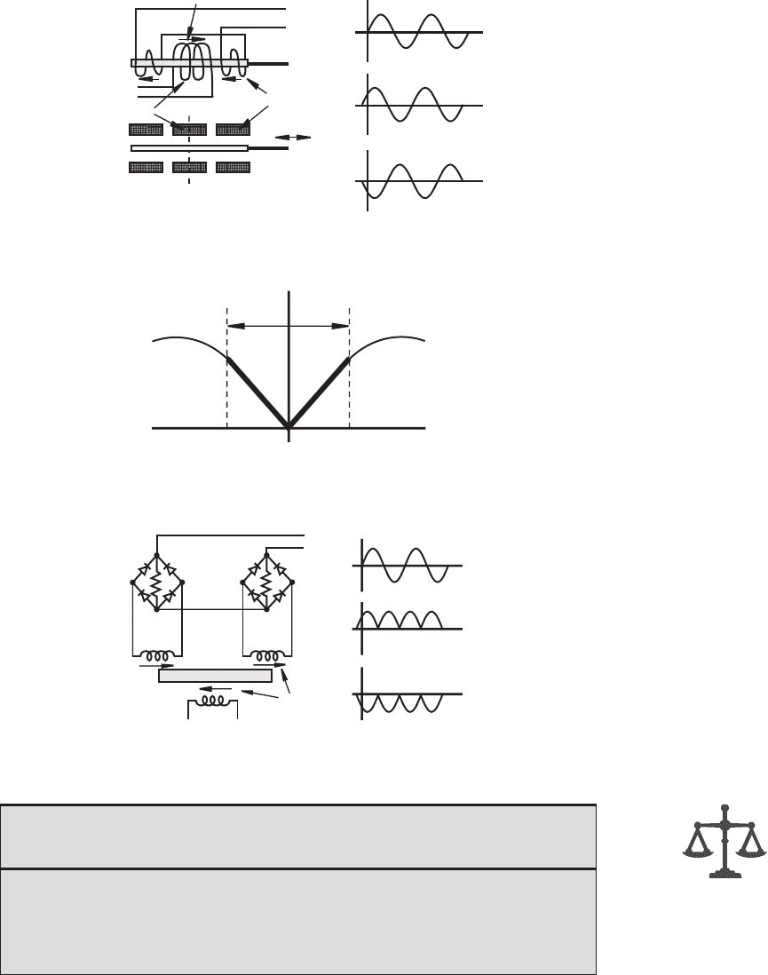
Figure 9.7 Linear variable differential transformer.
V
out
V
in
core centered
(null position)
secondary
primary
movable
iron core
V
in
V
out
V
out
excitation voltage
output voltage with
core left of null
output voltage with
core right of null
+
−
+
−
+−
++− −
magnetic field
Figure 9.8 LVDT linear range.
V
out
amplitude
core displacement
rightleft
linear
range
Figure 9.9 LVDT demodulation.
V
in
primary
secondary
V
out
secondary
core
V
in
V
out
V
out
excitation voltage
output voltage with
core left of null
output voltage with
core right of null
+
−
+
−
magnetic fields
and associated
voltage polarities
+
−
+
−
−
+
9.2 Position and Speed Measurement 381
■ CLASS DISCUSSION ITEM 9.2
LVDT Demodulation
Trace the currents through the diodes in the demodulation circuit shown in
Figure 9.9 for different core positions (null, left of null, and right of null) and explain
why the output voltage behaves as shown. Assume ideal diodes. Also, explain why
the output is 0 when the core is in the null or center position.
alc80237_ch09_375-430.indd 381alc80237_ch09_375-430.indd 381 10/01/11 10:09 PM10/01/11 10:09 PM
Confirming Pages
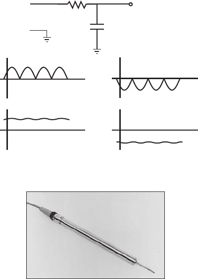
Figure 9.10 LVDT output filter.
+
−
V
out
V'
out
R
C
low-pass filter
output voltage with
core left of null
output voltage with
core right of null
V
out
V
out
V'
out
V'
out
Figure 9.11 Commercial LVDT. (Courtesy of Sensotec,
Columbus, OH)
382 CHAPTER 9 Sensors
As illustrated in Figure 9.10 , a low-pass filter may also be used to convert the
rectified output into a smoothed signal that tracks the core position. The cutoff fre-
quency of this low-pass filter must be chosen carefully to filter out the high fre-
quencies in the rectified wave but not the frequency components associated with the
core motion. The excitation frequency is usually chosen to be at least 10 times the
maximum expected frequency of the core motion to yield a good representation of
the time-varying displacement.
Commercial LVDTs, such as the one shown in Figure 9.11 , are available in
cylindrical forms with different diameters, lengths, and strokes. Often, they include
internal circuitry that provides a DC voltage proportional to displacement.
The advantages of the LVDT are accuracy over the linear range and an analog
output that may not require amplification. Also, it is less sensitive to wide ranges
in temperature than other position transducers (e.g., potentiometers, encoders, and
semiconductor devices). The LVDT’s disadvantages include limited range of motion
and limited frequency response. The overall frequency response is limited by inertial
effects associated with the core’s mass and the choice of the primary excitation fre-
quency and the filter cutoff frequency.
alc80237_ch09_375-430.indd 382alc80237_ch09_375-430.indd 382 10/01/11 10:09 PM10/01/11 10:09 PM

Confirming Pages
9.2 Position and Speed Measurement 383
A resolver is an analog rotary position sensor that operates very much like the
LVDT. It consists of a rotating shaft (rotor) with a primary winding and a stationary
housing (stator) with two secondary windings offset by 90 ⬚ . When the primary is
excited with an AC signal, AC voltages are induced in the secondary coils, which are
proportional to the sine and cosine of the shaft angle. Because of this, the resolver is
useful in applications where trigonometric functions of position are required.
Two other types of linear position sensors that measure linear displacement
directly, based on magnetic principles, are the voice coil and magnetostrictive posi-
tion transducers. Video Demos 9.5 and 9.6 show two example devices and describe
how they work.
9.2.4 Digital Optical Encoder
A digital optical encoder is a device that converts motion into a sequence of dig-
ital pulses. By counting a single bit or decoding a set of bits, the pulses can be
converted to relative or absolute position measurements. Encoders have both linear
and rotary configurations, but the most common type is rotary. Rotary encoders are
manufactured in two basic forms: the absolute encoder where a unique digital word
corresponds to each rotational position of the shaft, and the incremental encoder,
which produces digital pulses as the shaft rotates, allowing measurement of relative
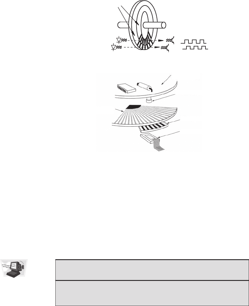
displacement of the shaft. As illustrated in Figure 9.12 , most rotary encoders are
composed of a glass or plastic code disk with a photographically deposited radial
pattern organized in tracks. As radial lines in each track interrupt the beam between
a photoemitter-detector pair, digital pulses are produced.
Video Demo 9.7 shows and describes all of the internal components of a small
digital encoder. In this case the code disk is made of stamped sheet metal. Video
Demos 9.8 and 9.9 describe two interesting applications of encoders: a computer
mouse and an industrial robot. View Video Demos 1.1 and 1.2 to see a demonstra-
tion of how the robot works and how the encoders are incorporated into the internal
design. Video Demo 1.5 shows another application of encoders where cost is a major
concern and a custom design is necessary.
The optical disk of the absolute encoder is designed to produce a digital word
that distinguishes N distinct positions of the shaft. For example, if there are eight
tracks, the encoder is capable of measuring 256 (2
8
) distinct positions corresponding
to an angular resolution of 1.406 ⬚ (360 ⬚ /256). The most common types of numerical
encoding used in the absolute encoder are gray and natural binary codes. To illus-
trate the action of an absolute encoder, the gray code and natural binary code disk
Video Demo
9.5Voice coil
9.6Magneto-
strictive position
sensor
■ CLASS DISCUSSION ITEM 9.3
LVDT Signal Filtering
Given the spectrum of a time-varying core displacement, what effect does the
choice of the primary excitation frequency have, and how should the low-pass filter
be designed to produce an output most representative of the displacement?
Video Demo
9.7Encoder
components
9.8Computer
mouse relative
encoder
9.9Adept robot
digital encoder
components
1.1Adept One
robot demon-
stration (8.0 MB)
1.2Adept One
robot internal
design and con-
struction (4.6 MB)
1.5Inkjet printer
components with
DC motors and
piezoelectric
inkjet head
alc80237_ch09_375-430.indd 383alc80237_ch09_375-430.indd 383 10/01/11 10:09 PM10/01/11 10:09 PM
Confirming Pages
Figure 9.12 Components of an optical encoder.
1 or more LED
photoemitters
phototransistor
photodetectors
code disk
shaft
tracks
digital output
signals
(a) schematic
(b) typical construction (Courtesy of
Lucas Ledex Inc., Vandalia, OH)
Electronics board
(Signal conditioning)
Rotating
encoder disk
LED light source
Stationary mask
Photodetector
384 CHAPTER 9 Sensors
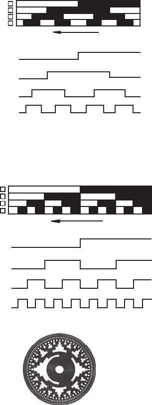
track patterns for a simple four-track (4-bit) encoder are illustrated in Figures 9.13
and 9.14 . The linear patterns and associated timing diagrams are what the photo-
detectors sense as the code disk circular tracks rotate with the shaft. The output bit
codes for both coding schemes are listed in Table 9.1.
The gray code is designed so that only one track (one bit) changes state for each
count transition, unlike the binary code where multiple tracks (bits) can change during
count transitions. This effect can be seen clearly in Figures 9.13 and 9.14 and in the last
two columns of Table 9.1. For the gray code, the uncertainty during a transition is only
one count, unlike with the binary code, where the uncertainty could be multiple counts.
■ CLASS DISCUSSION ITEM 9.4
Encoder Binary Code Problems
What is the maximum count uncertainty for a 4-bit gray code absolute encoder and
a 4-bit natural binary absolute encoder? At what decimal code transitions does the
maximum count uncertainty occur in a 4-bit natural binary absolute encoder?
alc80237_ch09_375-430.indd 384alc80237_ch09_375-430.indd 384 10/01/11 10:09 PM10/01/11 10:09 PM
Confirming Pages
Figure 9.13 4-bit gray code absolute encoder disk track patterns.
direction of positive track motion
fixed
sensors
bit 3 (MSB)
bit 2
bit 1
bit 0 (LSB)
0° 360°
bit 3
1
0
bit 2
1
0
bit 1
1
0
bit 0
1
0
Figure 9.14 4-bit natural binary absolute encoder disk track patterns.
(b) actual disk (Courtesy of Parker
Compumotor Division, Rohnert Park, CA)
(a) schematic and signals
direction of positive track motion
fixed
sensors
bit 3 (MSB)
bit 2
bit 1
bit 0 (LSB)
0° 360°
bit 3
1
0
1
0
1
0
1
0
bit 2
bit 1
bit 0
9.2 Position and Speed Measurement 385
Because the gray code provides data with the least uncertainty but the natural
binary code is the preferred choice for direct interface to computers and other digi-
tal devices, a circuit to convert from gray to binary code is desirable. Figure 9.15
shows a simple circuit that utilizes Exclusive OR (XOR) gates to perform this
alc80237_ch09_375-430.indd 385alc80237_ch09_375-430.indd 385 10/01/11 10:09 PM10/01/11 10:09 PM

Confirming Pages
Table 9.1 4-bit gray and natural binary codes
Decimal Code Rotation Range (⬚)
Natural binary
code (B
3
B
2
B
1
B
0
)
Gray code
(G
3
G
2
G
1
G
0
)
0 0–22.5 0000 0000
1 22.5–45 0001 0001
2 45–67.5 0010 0011
3 67.5–90 0011 0010
4 90–112.5 0100 0110
5 112.5–135 0101 0111
6 135–157.5 0110 0101
7 157.5–180 0111 0100
8 180–202.5 1000 1100
9 202.5–225 1001 1101
10 225–247.5 1010 1111
11 24 7.5–270 1011 1110
12 270–292.5 1100 1010
13 292.5–315 1101 1011
14 315–337.5 1110 1001
15 337.5–360 1111 1000
Figure 9.15
Gray-code-to-binary-code conversion.
MSB
LSB
G
3
B
3
G
2
B
2
G
1
G
0
B
1
B
0
386 CHAPTER 9 Sensors
function. The Boolean expressions that relate the binary bits ( B
i
) to the gray code
bits ( G
i
) are
B
3
G
3
=
B
2
B
3
G
2
⊕=
B
1
B
2
G
1
⊕=
B
0
B
1
G
0
⊕=
(9.1)
For a gray-code-to-binary-code conversion of any number of bits N (e.g., N ⫽ 4 as
previously), the most significant bits of the binary and gray codes are always identi-
cal ( B
N ⫺ 1
⫽ G
N ⫺ 1
), and for each other bit, the binary bit is the XOR combination:
B
i
⫽ B
i 1 1
丣 G
i
for i ⫽ 0 to N ⫺ 2. This pattern can be easily seen in the 4-bit
example above ( Equations 9.1 ).
alc80237_ch09_375-430.indd 386alc80237_ch09_375-430.indd 386 10/01/11 10:09 PM10/01/11 10:09 PM
Confirming Pages
Figure 9.16 Incremental encoder disk track patterns.
direction of positive track motion
fixed
sensors
A
B
INDEX
0° 360°
A
1
0
B
1
0
INDEX
1
0
(a) schematic and signals
(b) actual disk (Courtesy of Parker
Compumotor Division, Rohnert Park, CA)
9.2 Position and Speed Measurement 387
■ CLASS DISCUSSION ITEM 9.5
Gray-to-Binary-Code Conversion
Examine the validity of Equations 9.1 by applying them to the last two columns in
Table 9.1.
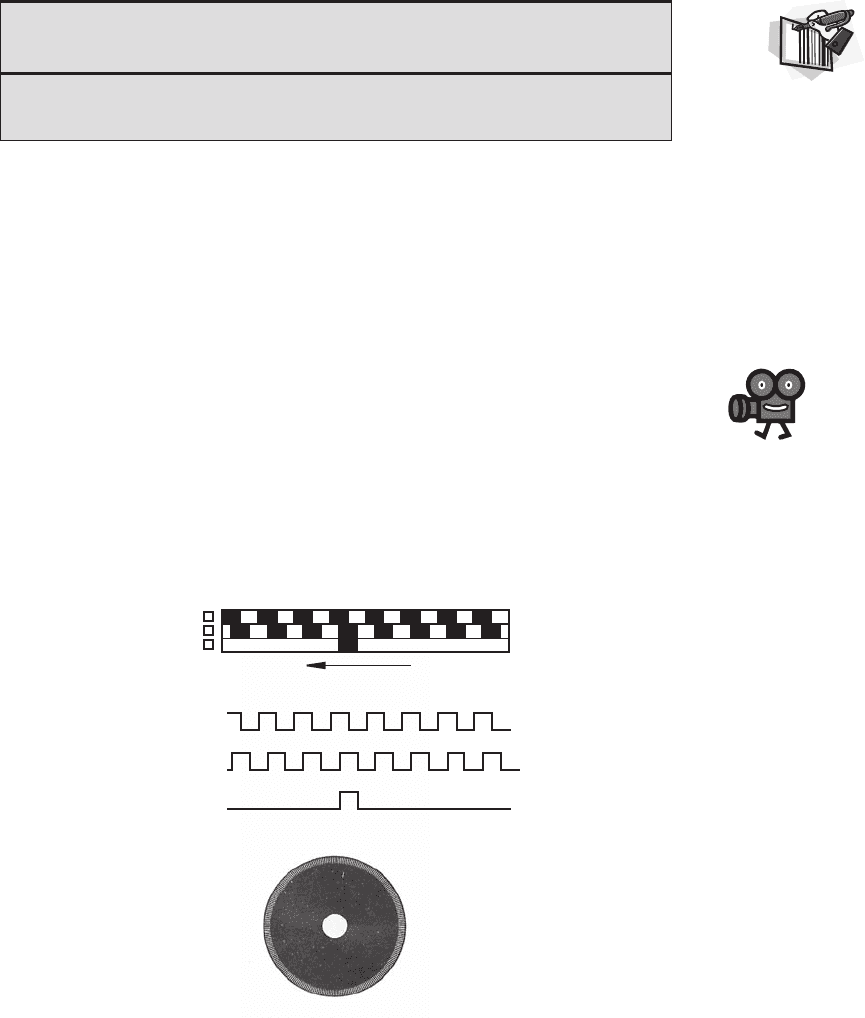
The incremental encoder, sometimes called a relative encoder, is simpler in
design than the absolute encoder. It consists of two tracks and two sensors whose
outputs are designated A and B. As the shaft rotates, pulse trains occur on A and B
at a frequency proportional to the shaft speed, and the lead-lag phase relationship
between the signals yields the direction of rotation as described in detail below. The
code disk pattern and output signals A and B are illustrated in Figure 9.16 . By count-
ing the number of pulses and knowing the resolution of the disk, the angular motion
can be measured. A and B are 1/4 cycle out of phase with each other and are known
as quadrature signals. Often a third output, called INDEX, yields one pulse per
revolution, which is useful in counting full revolutions. It is also useful to define a
reference or zero position.
Figure 9.16a illustrates a configuration using two separate tracks for A and B,
but a more common configuration uses a single track (see Figure 9.16b and
Video Demo 9.7) with the A and B sensors offset a quarter cycle on the track to
Video Demo
9.7Encoder
components
alc80237_ch09_375-430.indd 387alc80237_ch09_375-430.indd 387 10/01/11 10:09 PM10/01/11 10:09 PM
Confirming Pages
Figure 9.17 Quadrature direction sensing and resolution enhancement.
forward (CW) reverse (CCW)
A
B
CW
CCW
CW
CCW
CW
CCW
1X
2X
4X
388 CHAPTER 9 Sensors
yield the same signal pattern. A single-track code disk is simpler and cheaper to
manufacture.
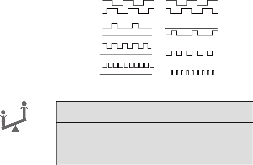
The quadrature signals A and B can be decoded to yield angular displacement
and the direction of rotation as shown in Figure 9.17 . Pulses appear on one of two
output lines (CW and CCW) corresponding either to clockwise (CW) rotation or
counterclockwise (CCW) rotation. Decoding transitions of A and B using sequential
logic circuits can provide three different resolutions: 1X, 2X, and 4X. The 1X reso-
lution provides an output transition at each negative edge of signal A or B, resulting
in a single pulse for each quadrature cycle. The 2X resolution provides an output
transition at every negative or positive edge of signal A or B, resulting in two times
the number of output pulses. The 4X resolution provides an output pulse at every
positive and negative edge of signal A or B, resulting in four times the number of
output pulses. The direction of rotation is determined by the level of one quadrature
signal during an edge transition of the second quadrature signal. For example, in the
1X mode, A ⫽ ↓ with B ⫽ 1 implies clockwise rotation, and B ⫽ ↓ with A ⫽ 1
implies counterclockwise rotation. If we only had one signal instead of both A and B,
it would be impossible to determine the direction of rotation. Furthermore, shaft
jitter around an edge transition in the single signal would result in erroneous pulses
(see Class Discussion Item 9.6).
■ CLASS DISCUSSION ITEM 9.6
Encoder 1X Circuit with Jitter
An incremental encoder connected to a 1X quadrature decoder circuit is experi-
encing a small rotational vibration with an amplitude roughly equivalent to one
quadrature pulse width. During this vibration, you observe many pulses on both the
CW and CCW lines but no net change in the output of the up-down counter. Explain
why this happens.
alc80237_ch09_375-430.indd 388alc80237_ch09_375-430.indd 388 10/01/11 10:09 PM10/01/11 10:09 PM

Confirming Pages
Figure 9.18 1X quadrature decoder circuit.
D
C
Q
up-down
counter
up
down
binary
count
output
A
B
CW
CCW
CLR
D
C
Q
CLR Q
Q
9.2 Position and Speed Measurement 389
Figure 9.18 shows a circuit that will yield the 1X resolution by creating and
counting pulses at specific negative edges of the quadrature signals. The D flip-
flops decode whether the shaft is rotating clockwise or counterclockwise, and this
information is used to drive an up-down counter to keep the current pulse count for
the encoder rotation. In addition to the edges detected for the 1X resolution, circuits
can be designed to detect other edges in the quadrature signals resulting in two times
(2X) and four times (4X) the base resolution (1X). These quadrature decoder cir-
cuits can be constructed with discrete components, but they are also available on ICs
(e.g., Hewlett Packard’s HCTL-2016). Quadrature decoding can also be done with
software running on a microcontroller (Question 9.11).
Incremental encoders provide more resolution at lower cost than absolute
encoders, but they measure only relative motion and do not provide absolute posi-
tion directly. However, an incremental encoder can be used in conjunction with a
limit switch to define absolute position relative to a reference position defined by the
switch. Absolute encoders are chosen in applications where establishing a reference
position is impractical or undesirable.
■ CLASS DISCUSSION ITEM 9.7
Robotic Arm with Encoders
When a robotic arm with absolute encoders on its joints is powered up, the robot
knows exactly where its links are relative to its base. If the absolute encoders were
replaced with incremental encoders, would this remain true? If not, how would the
robot establish a home or zero reference position for the arm?
THREADED DESIGN EXAMPLE
DC motor position and speed controller—Digital encoder interface C.4
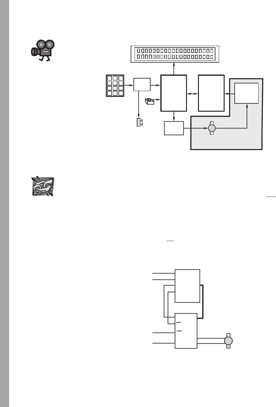
The figure below shows the functional diagram for Threaded Design Example C (see Section
1.3 and Video Demo 1.8), with the portion described here highlighted.
alc80237_ch09_375-430.indd 389alc80237_ch09_375-430.indd 389 10/01/11 10:09 PM10/01/11 10:09 PM
Confirming Pages
390 CHAPTER 9 Sensors
microcontrollers
SLAVE
PIC
MASTER
PIC
H-bridge
driver
liquid crystal display
DC motor with
digital position encoder
1 2 3
4 5 6
7 8 9
*
0 #
keypad
keypad
decoder
button
buzzer
quadrature
decoder
and counter
The following figure shows all components and interconnections required to read the
digital encoder’s position from the slave PIC. A commercially available quadrature decoder/
counter interface IC, the HCTL-2016, is the main component in the design. Detailed informa-
tion about this component can be found in the data sheet at Internet Link 9.3. The HCTL-2016
requires a clock signal to operate. In this design, it is provided by a clock output on the master
PIC. The master PIC also resets the encoder counter at the appropriate time (via the RST line)
to define a zero position. The digital encoder quadrature signals (channels A and B) are also
connected to the HTCL-2016. Because the HTCL-2016 contains a 16-bit counter, and the
interface to the slave PIC is via the 8-bit PORTB, the data must be retrieved one byte at a time.
The thick line connecting PORTB on the PIC to D0-7 on the HCTL-2016 in the wiring dia-
gram indicates multiple wires (in this case, an 8-wire cable). The SEL pin is used to indicate
which byte is being read. Finally, the OE pin is used to latch the encoder values before they
are read by the PIC.
DC motor
with
encoder
+
HCTL-2016
CLK
CHA
CHB
D0-7
PIC16F84
SEL
PORTB
RA2
RA3
RA0
RA1
OE
RST
17
18
1
2
6–13
3
4
5
2
1, 15–9
7
6
controlled
by the master PIC
for communication
with the master PIC
Shown below is the slave PIC code, which monitors the digital encoder position and
transmits the data back to the master PIC upon request. The full code for both PICs is
Video Demo
1.8DC motor
position and
speed controller
Internet Lin
k
9.3HTCL-2016
quadrature
decoder/counter
alc80237_ch09_375-430.indd 390alc80237_ch09_375-430.indd 390 10/01/11 10:09 PM10/01/11 10:09 PM
