Alciatore D.G., Histand M.B. Introduction to Mechatronics and Measurement Systems
Подождите немного. Документ загружается.


Confirming Pages
9.3 Stress and Strain Measurement 391
presented in Threaded Design Example C.3. The serial communication between the PICs is
also described there.
' Define I/O pin names and constants
enc_start Var PORTA.0 ' signal line used to start encoder data transmission
enc_serial Var PORTA.1 ' serial line used to transmit encoder data
enc_sel Var PORTA.2 ' encoder data byte select (0:high 1:low)
enc_oe Var PORTA.3 ' encoder output enable latch signal (active low)
enc_mode Con 2 ' 9600 baud mode for serial communication
' Main loop
start:
' Wait for the start signal from the master PIC to go high
While (enc_start == 0) : Wend
' Enable the encoder output (latch the counter values)
Low enc_oe
' Send out the high byte of the counter
SEROUT enc_serial, enc_mode, [PORTB]
' Wait for the start signal from the master PIC to go low
While (enc_start == 1) : Wend
' Send out the low byte of the counter
High enc_sel
SEROUT enc_serial, enc_mode, [PORTB]
' Disable the encoder output
High enc_oe
Low enc_sel
goto start ' wait for next request
9.3 STRESS AND STRAIN MEASUREMENT
Measurement of stress in a mechanical component is important when assessing
whether or not the component is subjected to safe load levels. Stress and strain mea-
surements can also be used to indirectly measure other physical quantities such as
force (by measuring strain of a flexural element), pressure (by measuring strain in
a flexible diaphragm), and temperature (by measuring thermal expansion of a mate-
rial). The most common transducer used to measure strain is the electrical resistance
strain gage. As we will see, stress values can be determined from strain measure-
ments using principles of solid mechanics.
Basic stress and strain relations and planar stress analysis techniques are pre-
sented in Appendix C for your review if necessary.
alc80237_ch09_375-430.indd 391alc80237_ch09_375-430.indd 391 10/01/11 10:09 PM10/01/11 10:09 PM
Confirming Pages
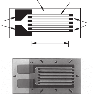
Figure 9.19 Metal foil strain gage construction.
foil grid lines
solder
tabs
backing
end
loops
active length
(a) schematic
(b) actual (Courtesy of Measurements
Group Inc., Raleigh, NC)
392 CHAPTER 9 Sensors
9.3.1 Electrical Resistance Strain Gage
The most common transducer for experimentally measuring strain in a mechanical
component is the bonded metal foil strain gage illustrated in Figure 9.19 . It consists
of a thin foil of metal, usually constantan, deposited as a grid pattern onto a thin plas-
tic backing material, usually polyimide. The foil pattern is terminated at both ends
with large metallic pads that allow leadwires to be easily attached with solder. The
entire gage is usually very small, typically 5 to 15 mm long.
To measure strain on the surface of a machine component or structural mem-
ber, the gage is adhesively bonded directly to the component, usually with epoxy
or cyanoacrylate. The backing makes the foil gage easy to handle and provides a
good bonding surface that also electrically insulates the metal foil from the com-
ponent. Leadwires are then soldered to the solder tabs on the gage. When the
component is loaded, the metal foil deforms, and the resistance changes in a pre-
dictable way (see below). If this resistance change is measured accurately, the
strain on the surface of the component can be determined. Strain measurements
allow us to determine the state of stress on the surface of the component, where
stresses typically have their highest values. Knowing stresses at critical locations
on a component under load can help a designer validate analytical or numerical
results (e.g., from a finite element analysis) and verify that stress levels remain
below safe limits for the material (e.g., below the yield strength). It is important to
note that, because strain gages are finite in size, a measurement actually reflects
an average of the strain over a small area. Hence, making measurements where
stress gradients are large (e.g., where there is stress concentration) can yield poor
results.
alc80237_ch09_375-430.indd 392alc80237_ch09_375-430.indd 392 10/01/11 10:09 PM10/01/11 10:09 PM
Confirming Pages
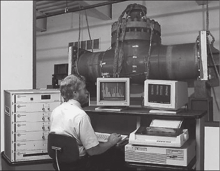
Figure 9.20 Strain gage application. (Courtesy of Measurements
Group Inc., Raleigh, NC)
9.3 Stress and Strain Measurement 393
Experimental stress analysis (e.g., with strain gages) and analytical or numerical
stress analysis (e.g., with finite element analysis) are both important to design reli-
able mechanical parts. The two approaches should be considered complements to
each other and not replacements. Finite element analysis involves many assumptions
about material properties, load application, and boundary conditions that may not
accurately model the actual component when it is manufactured and loaded. Strain
gage measurements may also have some inaccuracies due to imperfect bonding and
alignment on the component surface and due to uncompensated temperature effects.
Also, only specific locations can be checked with strain gages because space and
access on the component can be limiting factors.
Effects that are easily measured with strain gages but difficult to model with
finite element analysis include stresses resulting from mechanical assembly of com-
ponents and complex loading and boundary conditions. These and other effects are
often difficult to predict and model accurately with analytical and numerical methods.
Experimental stress applications usually involve mounting a large number of
strain gages on a mechanical component, as illustrated in Figure 9.20 , before it is
loaded. Experimental strain values are usually acquired through an automated data
acquisition system. The strain data can be converted to stresses in the object under
different loading conditions, and the stresses can be compared to analytical and
numerical finite element analysis results.
To understand how a strain gage is used to measure strain, we first look at how
the resistance of the foil changes when deformed. The metal foil grid lines in the
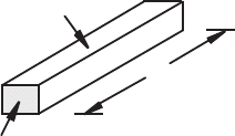
active portion of the gage (see Figure 9.19a) can be approximated by a single rectan-
gular conductor as illustrated in Figure 9.21 , whose total resistance is given by
R
ρL
A
------
=
(9.2)
alc80237_ch09_375-430.indd 393alc80237_ch09_375-430.indd 393 10/01/11 10:09 PM10/01/11 10:09 PM
Confirming Pages
Figure 9.21 Rectangular conductor.
A
ρ
L
w
h
394 CHAPTER 9 Sensors
where is the foil metal resistivity, L is the total length of the grid lines, and A is the
grid line cross-sectional area. The gage end loops and solder tabs have negligible
effects on the gage resistance because they typically have a much larger cross section
than the foil lines.
To see how the resistance changes under deformation, we need to take the dif-
ferential of Equation 9.2. If we first take the natural logarithm of both sides,
Rln
ρ
ln Lln Aln–+=
(9.3)
taking the differential yields the following expression for the change in resistance
given material property and geometry changes in the conductor:
dRR⁄ dρρ⁄ dLL⁄ dAA⁄–+=
(9.4)
As we would expect, the signs in this equation imply that the resistance of the
conductor increases (d R > 0) with increased resistivity and increased length and
decreases with increased cross-sectional area. Because the cross-sectional area of
the conductor is
Awh=
(9.5)
the area differential term is
dA
A
------ -
w dh⋅ h dw⋅+
wh⋅
------------------------------------
dh
h
------
dw
w
-------
+==
(9.6)
From the definition of Poisson’s ratio (see Appendix C),
dh
h
------
ν
dL
L
------
–=
(9.7)
and
dw
w
-------
ν
dL
L
------
–=
(9.8)
so
dA
A
------ -
2– ν
dL
L
------
2– νε
axial
==
(9.9)
where ε
axial
is the axial strain in the conductor (see Appendix C). When the conduc-
tor is elongated (ε
axial
> 0), the cross-sectional area decreases (d A / A < 0), causing the
resistance to increase.
alc80237_ch09_375-430.indd 394alc80237_ch09_375-430.indd 394 10/01/11 10:09 PM10/01/11 10:09 PM

Confirming Pages
9.3 Stress and Strain Measurement 395
Using Equation 9.9 , Equation 9.4 can be expressed as
dRR⁄ε
axial
12ν+()dρρ⁄+=
(9.10)
Dividing through by ε
axial
gives
dRR⁄
ε
axial
-------------- 12ν+
dρρ⁄
ε
axial
-------------
+=
(9.11)
The first two terms on the right-hand side, 1 and 2 , represent the change in resis-
tance due to increased length and decreased area. The last term (d / )/(ε
axial
) rep-
resents the piezoresistive effect in the material, which explains how the resistivity of
the material changes with strain. All three terms are approximately constant over the
operating range of typical strain gage metal foils.
Commercially available strain gage specifications usually report a constant gage
factor F to represent the right-hand side of Equation 9.11. This factor represents the
material characteristics of the gage that relate the gage’s change in resistance to strain:
F
ΔRR⁄
ε
axial
---------------
=
(9.12)
Thus, when a gage of known resistance R and gage factor F is bonded to the surface
of a component and the component is then loaded, we can determine the strain in the
gage ε
axial
simply by measuring the change in resistance of the gage Δ R:
ε
axial
ΔRR⁄
F
---------------
=
(9.13)
This gage strain is the strain on the surface of the loaded component in the direction
of the gage’s long dimension.
For the bonded metal foil strain gage, the gage factor F is usually close to 2, and
the gage resistance R is close to 120 Ω. Strain gage suppliers also report a trans-
verse sensitivity for the gage, which is a measure of the resistance changes in the
end loops and grid lines due to strain in the transverse direction. The transverse
sensitivity for a bonded metal foil gage is usually close to 1%. This number predicts
the gage’s sensitivity to transverse strains: those perpendicular to the measuring axis
of the gage. A gage experiencing 50 ε (50 ⫻ 10
⫺ 6
, read as “50 microstrain”) in the
axial direction and 100 ε in the transverse direction with a transverse sensitivity of
1% will sense 51 ε (50 ⫹ 1% of 100), not 50 ε.
If a 120 Ω strain gage with gage factor 2.0 is used to measure a strain of 100 ε (100 ⫻ 10
⫺ 6
),
how much does the resistance of the gage change from the unloaded state to the loaded
state?
Equation 9.12 tells us that
ΔRRFε⋅⋅=
so the change in resistance would be
ΔR 120 Ω
()
2.0
()
0.000100
()
0.024 Ω==
Strain Gage Resistance Changes
EXAMPLE 9.1
alc80237_ch09_375-430.indd 395alc80237_ch09_375-430.indd 395 10/01/11 10:09 PM10/01/11 10:09 PM

Confirming Pages
Figure 9.22 Static balanced bridge circuit.
+
Hi Z
VM
V
ex
R
1
: strain gage
R
2
R
4
: potentiomete
r
R
3
i
1
i
2
i
4
i
3
A
B
396 CHAPTER 9 Sensors
9.3.2 Measuring Resistance Changes
with a Wheatstone Bridge
To use strain gages to accurately measure strains experimentally, we need to be able
to accurately measure small changes in resistance. The most common circuit used to
measure small changes in resistance is the Wheatstone bridge, which consists of a
four-resistor network excited by a DC voltage. A Wheatstone bridge is better than
a simple voltage divider because it can be easily balanced to establish an accurate
zero position, it allows temperature compensation, and it can provide better sensitiv-
ity and accuracy. There are two different modes of operation of a Wheatstone bridge
circuit: the static balanced mode and the dynamic unbalanced mode. For the static
balanced mode, illustrated in Figure 9.22 , R
2
and R
3
are precision resistors, R
4
is a
precision potentiometer (variable resistor) with an accurate scale for displaying the
resistance value, and R
1
is the strain gage resistance for which the change is to be
measured. To balance the bridge, the variable resistor is adjusted until the voltage
between nodes A and B is 0. In the balanced state, the voltages at A and B must be
equal so
i
1
R
1
= i
2
R
2
(9.14)
Also, because the high-input impedance voltmeter between A and B is assumed to
draw no current,
i
1
i
4
V
ex
R
1
R
4
+
-----------------
==
(9.15)
and
i
2
i
3
V
ex
R
2
R
3
+
-----------------
==
(9.16)
■ CLASS DISCUSSION ITEM 9.8
Piezoresistive Effect in Strain Gages
For a typical metal foil strain gage with a gage factor of 2.0, how large is the piezo-
resistive effect in comparison to the effects of change in area and change in length?
alc80237_ch09_375-430.indd 396alc80237_ch09_375-430.indd 396 10/01/11 10:09 PM10/01/11 10:09 PM
Confirming Pages
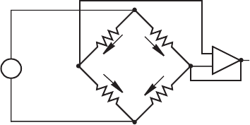
Figure 9.23 Dynamic unbalanced bridge circuit.
+
V
ex
R
1
R
2
R
4
R
3
i
1
i
2
V
ou
t
differential
buffer
amplifier
−
+
9.3 Stress and Strain Measurement 397
where V
ex
is the DC voltage applied to the bridge called the excitation voltage. Sub-
stituting these expressions into Equation 9.14 and rearranging gives
R
1
R
4
-----
R
2
R
3
-----
=
(9.17)
If we know R
2
and R
3
accurately and we note the value for R
4
on the precision poten-
tiometer scale, we can accurately calculate the unknown resistance R
1
as
R
1
R
4
R
2
R
3
----------- -
=
(9.18)
Note that this result is independent of the excitation voltage, V
ex
(see Class Discus-
sion Item 9.9).
The static balanced mode of operation can be used to measure a gage’s resis-
tance under fixed load, but usually balancing is done only as a preliminary step
to measuring changes in gage resistance. In dynamic deflection operation (see
Figure 9.23 ), again with R
1
representing a strain gage and R
4
representing a poten-
tiometer, the bridge is first balanced, before loads are applied, by adjusting R
4
until
there is no output voltage. Then changes in the strain gage resistance R
1
that occur
under time-varying load can be determined from changes in the output voltage.
The output voltage can be expressed in terms of the resistor currents as
V
out
i
1
R
1
i
2
R
2
– i
1
R
4
– i
2
R
3
+==
(9.19)
and the excitation voltage can be related to the currents:
V
ex
i
1
R
1
R
4
+()i
2
R
2
R
3
+()==
(9.20)
Solving for i
1
and i
2
in terms of V
ex
in Equation 9.20 and substituting these into the
first expression in Equation 9.19 gives
V
out
V
ex
R
1
R
1
R
4
+
-----------------
R
2
R
2
R
3
+
-----------------–
⎝⎠
⎛⎞
=
(9.21)
When the bridge is balanced, V
out
is 0 and R
1
has a known value. When R
1
changes value, as the strain gage is loaded, Equation 9.21 can be used to relate this
voltage change Δ V
out
to the change in resistance Δ R
1
. To find this relation, we can
alc80237_ch09_375-430.indd 397alc80237_ch09_375-430.indd 397 10/01/11 10:09 PM10/01/11 10:09 PM

Confirming Pages
398 CHAPTER 9 Sensors
replace R
1
by its new resistance R
1
⫹ Δ R
1
and V
out
by the output deflection voltage
Δ V
out
. Then Equation 9.21 gives
ΔV
out
V
ex
------------
R
1
ΔR
1
+
R
1
ΔR
1
R
4
++
----------------------------------
R
2
R
2
R
3
+
-----------------–=
(9.22)
Rearranging this equation gives us the desired relation between the change in
resistance and the measured output voltage:
ΔR
1
R
1
---------
R
4
R
1
-----
ΔV
out
V
ex
------------
R
2
R
2
R
3
+
-----------------
+
⎝⎠
⎛⎞
1
ΔV
out
V
ex
------------–
R
2
R
2
R
3
+
-----------------
–
⎝⎠
⎛⎞
---------------------------------------------------- 1–=
(9.23)
By measuring the change in the output voltage Δ V
out
, we can determine the gage
resistance change Δ R
1
from Equation 9.23 and can compute the gage strain from
Equation 9.13. The differential buffer amplifier shown in Figure 9.23 provides high
input impedance (i.e., it does not load the bridge) and high gain for the small change
in voltage due to the small change in resistance.
■ CLASS DISCUSSION ITEM 9.9
Wheatstone Bridge Excitation Voltage
What undesirable effects can the magnitude of the excitation voltage have on the
resistance change measurements made with a Wheatstone bridge?
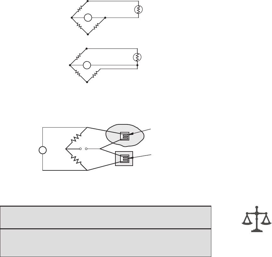
Figure 9.24 illustrates the effects of leadwires when using a strain gage located
far from the bridge circuit. Figure 9.24a illustrates a two-wire connection from a
strain gage to a bridge circuit. With this configuration, each of the leadwire resis-
tances R
⬘
adds to the resistance of the strain gage branch of the bridge. The problem
with this is that, if the leadwire temperature changes, it causes changes in the resis-
tance of the bridge branch. This effect can be substantial if the leadwires are long
and extend through environments where the temperature changes. Figure 9.24b
illustrates a three-wire connection that solves this problem. With this configura-
tion, equal leadwire resistances are added to adjacent branches in the bridge so the
effects of changes in the leadwire resistances offset each other. The third leadwire
is connected to the high-input impedance voltage measuring circuit, and its resis-
tance has a negligible effect because it carries negligible current. The three wires
are usually in the form of a small ribbon cable to ensure they experience the same
temperature changes and to minimize electromagnetic interference due to inductive
coupling.
In addition to temperature effects in leadwires, temperature changes in the
strain gage can cause significant changes in resistance, which would lead to erro-
neous measurements. A convenient method for eliminating this effect is to use
alc80237_ch09_375-430.indd 398alc80237_ch09_375-430.indd 398 10/01/11 10:09 PM10/01/11 10:09 PM
Confirming Pages
Figure 9.24 Leadwire effects in 1/4 bridge circuits.
R'
R'
(a) 2-wire connection
(b) 3-wire connection
R
2
R
1
R
3
R
4
R'
R'
R
2
VM
VM
R
1
R
3
R
4
Figure 9.25 Temperature compensation with a dummy gage in a half bridge circuit.
+
part to be loaded
unstressed material of same
composition and at same temperature
dummy gage
active gage
9.3 Stress and Strain Measurement 399
the circuit (called a half bridge) illustrated in Figure 9.25 , where two of the four
bridge legs contain strain gages. The gage in the top branch is the active gage used
to measure surface strains on a component to be loaded. The second “dummy”
gage is mounted to an unloaded sample of material identical in composition to
the component. If this sample is kept at the same temperature as the component
by keeping it in close proximity, the resistance changes in the two gages due to
temperature cancel because they are in adjacent branches of the bridge circuit.
Therefore, the bridge generates an unbalanced voltage only in response to strain
in the active gage.
■ CLASS DISCUSSION ITEM 9.10
Bridge Resistances in Three-Wire Bridges
What must be true about the bridge resistance R
4
for the three-wire configuration
shown in Figure 9.24b to result in a balanced bridge ( V
o
⫽ 0) in the no-strain condi-
tion? (Hint: Use Equation 9.21 and assume R
2
⫽ R
3
.)
alc80237_ch09_375-430.indd 399alc80237_ch09_375-430.indd 399 10/01/11 10:09 PM10/01/11 10:09 PM
Confirming Pages
Figure 9.26 Bar under uniaxial stress.
P
σ
x
σ
x
strain
gage (ε
x
)
400 CHAPTER 9 Sensors
9.3.3 Measuring Different States of Stress
with Strain Gages
Mechanical components may have complex shapes and are often subjected to com-
plex loading conditions. In these cases, it is difficult to predict the orientation of
principal stresses at arbitrary points on the component. However, with some geom-
etries and loading conditions, the principal axes are known, and measuring the state
of stress is easier.
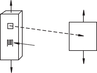
If a component is loaded uniaxially (i.e., loaded in only one direction in tension
or compression), the state of stress in the component can be determined with a single
gage mounted in the direction of the load. Figure 9.26 illustrates a bar in tension and
the associated state of stress. By measuring the strain ε
x
, the stress is obtained using
Hooke’s law (see Appendix C):
σ
x
Eε
x
=
(9.24)
where the axial stress in the
x
is given by
σ
x
P
A
---
=
(9.25)
where A is the bar’s cross-sectional area. Therefore, the force P applied to the bar
can be determined from the strain gage measurement:
PAEε
x
=
(9.26)
If a component is known to be loaded biaxially (i.e., loaded in two orthogonal
directions in tension or compression), the state of stress in the component can be
determined with two gages aligned with the stress directions. Figure 9.27 illustrates
a pressurized tank and the associated state of stress. By measuring the strains ε
x
and
ε
y
, the stresses in the tank shell can be determined from Hooke’s law generalized to
two dimensions:
ε
x
σ
x
E
----- ν
σ
y
E
-----
–=
(9.27)
ε
y
σ
y
E
----- ν
σ
x
E
-----
–=
(9.28)
alc80237_ch09_375-430.indd 400alc80237_ch09_375-430.indd 400 10/01/11 10:09 PM10/01/11 10:09 PM
