Alciatore D.G., Histand M.B. Introduction to Mechatronics and Measurement Systems
Подождите немного. Документ загружается.


Confirming Pages
7.7 Interfacing Common PIC Peripherals 301
' Check column 3
High col1 : High col2 : Low col3
If (row1 == 0) Then
' key 3 is down
Endif
If (row2 == 0) Then
' key 6 is down
Endif
If (row3 == 0) Then
' key 9 is down
Endif
If (row4 == 0) Then
' key # is down
Endif
' Continue polling
Goto loop
End
Lab Exercise 11 explores how to wire and accept input from a numeric keypad.
In this case, three keys of a keypad are used to control the motion of a DC motor.
Video Demo 7.4 shows a demonstration of the example in action.
7.7.2 LCD Display
The other common peripheral device we want to highlight is a standard Hitachi
44780-based liquid crystal display (LCD). LCDs come in different shapes and
sizes that can support different numbers of rows of text and different numbers of
characters per row. The standard choices for the number of characters and rows are
8 2, 16 1, 16 2, 16 4, 20 2, 24 2, 40 2, and 40 4. An example of
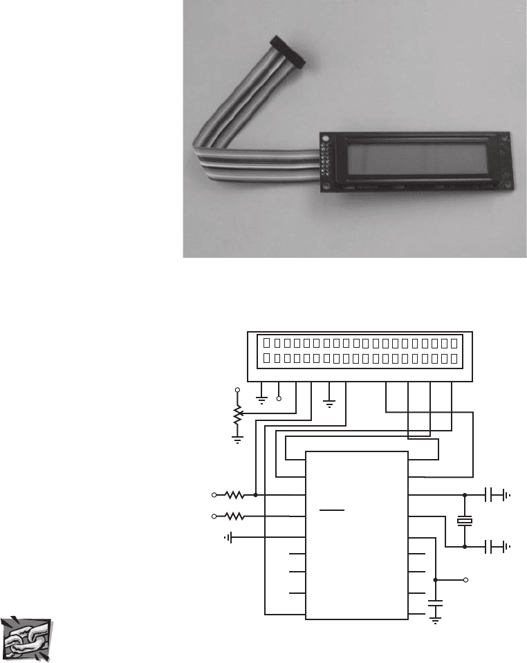
a common 20 2 LCD is shown in Figure 7.12 . It is illustrated schematically in the
top of Figure 7.13 . Applications of LCDs include displaying messages or informa-
tion to the user (e.g., a home thermostat display, a microwave oven display, or a digi-
tal clock) and displaying a hierarchical input menu for changing settings and making
selections (e.g., a copy machine or printer display).
For an LCD display with 80 characters or less (all but the 40 4 just listed),
the display is controlled via 14 pins. The names and descriptions of these pins are
listed in Table 7.6 . PicBasic Pro offers a simple statement called Lcdout to control
an LCD display. LCD displays with more than 80 characters (40 4) use a 16-pin
header with different pin assignments not compatible with Lcdout. A 14-pin LCD
can be controlled via four or eight data lines. PicBasic Pro supports both, but it is
recommended that you use four lines to minimize the number of I/O pins required.
Figure 7.13 shows the recommended interface to the PIC using a four-line data bus.
Commands and data are sent to the display via lines DB4 through DB7, and lines DB0
through DB3 (pins 7 through 10) are not used. Pin RA4 is connected to 5 V through
a pull-up resistor because it is an open drain output (see details in Section 7.8 ).
The potentiometer connected to V
ee
is used to adjust the contrast between the
Video Demo
7.4Pulse-
width-modulation
speed control of
a DC motor, with
keypad input
Lab Exercise
Lab 11Pulse-
width-modulation
motor speed
control with a
PIC
alc80237_ch07_258-345.indd 301alc80237_ch07_258-345.indd 301 12/01/11 12:52 PM12/01/11 12:52 PM
Confirming Pages
Figure 7.12 Photograph of an LCD.
Figure 7.13 LCD PIC interface.
PIC16F84
RA1
RA0
OSC1
OSC2
V
dd
RB7
RB6
RB5
RB4
1
2
3
4
5
6
7
8
9
10
11
12
13
14
15
16
17
18
5 V
22 pF
22 pF
4 MHz
1 k
5 V
0.1 μF
20 ⫻ 2 LCD character display
V
ss
V
cc
V
ee
RS R/W E
DB4 DB5 DB6 DB7
12
3
4
5
6
11 12
13
14
5 V
5 V
20 k
pot
5 V
1 k
RA2
RA3
RA4
MCLR
V
ss
RB0
RB1
RB2
RB3
302 CHAPTER 7 Microcontroller Programming and Interfacing
foreground and background shades of the display. The RS, R/W, and E lines are
controlled automatically by PicBasic Pro when communicating with the display.
Detailed information about LCD displays and how to write your own interface can
be found online (see Internet Link 7.7).
Internet Lin
k
7.7PIC I/O
interface devices
and useful
accessories
alc80237_ch07_258-345.indd 302alc80237_ch07_258-345.indd 302 12/01/11 12:52 PM12/01/11 12:52 PM

Confirming Pages
7.7 Interfacing Common PIC Peripherals 303
With the hardware interface shown in Figure 7.13 , the display can be controlled
with the PicBasic Pro statement Lcdout. The simplest form of this statement is Lcd-
out text (e.g., Lcdout “Hello world” ) where text is a string constant. The statement
also supports various commands for controlling the display and cursor and for out-
putting numbers and data in different formats. Refer to the description of the Lcd-
out statement in the PicBasic Pro compiler manual for more information on these
options. Here is a simple example to illustrate the use of the commands and format
controls. If x is defined as a byte variable and currently contains the value 123, the
following statement,
Lcdout $FE, 1, "Current value for x:", $FE, $C0, " ", DEC x
would clear the display and output the following two-line message:
Current value for x:
123
The code word $FE indicates to the display that the next item is a command. In the
example above, command 1 clears the display and command $C0 moves the cursor
to the beginning of the next line. The prefix DEC is used to instruct the display to
output the following number in its decimal digit form rather than its corresponding
ASCII character. Video Demo 7.5 shows a demonstration of the example Lcdout
statement above, where the displayed number is incremented by a Fo r loop .
Video Demo
7.5LCD display
Table 7.6 Liquid crystal display pin descriptions
Pin Symbol Description
1
V
ss
Ground reference
2
V
cc
Power supply (5 V)
3
V
ee
Contrast adjustment voltage
4 RS Register select (0: instruction input; 1: data input)
5 R/W Read/write status (0: write to LCD; 1: read from LCD RAM)
6 E Enable signal
7–14 DB0–DB7 Data bus lines
THREADED DESIGN EXAMPLE
DC motor position and speed controller—Keypad and LCD interfaces C.2
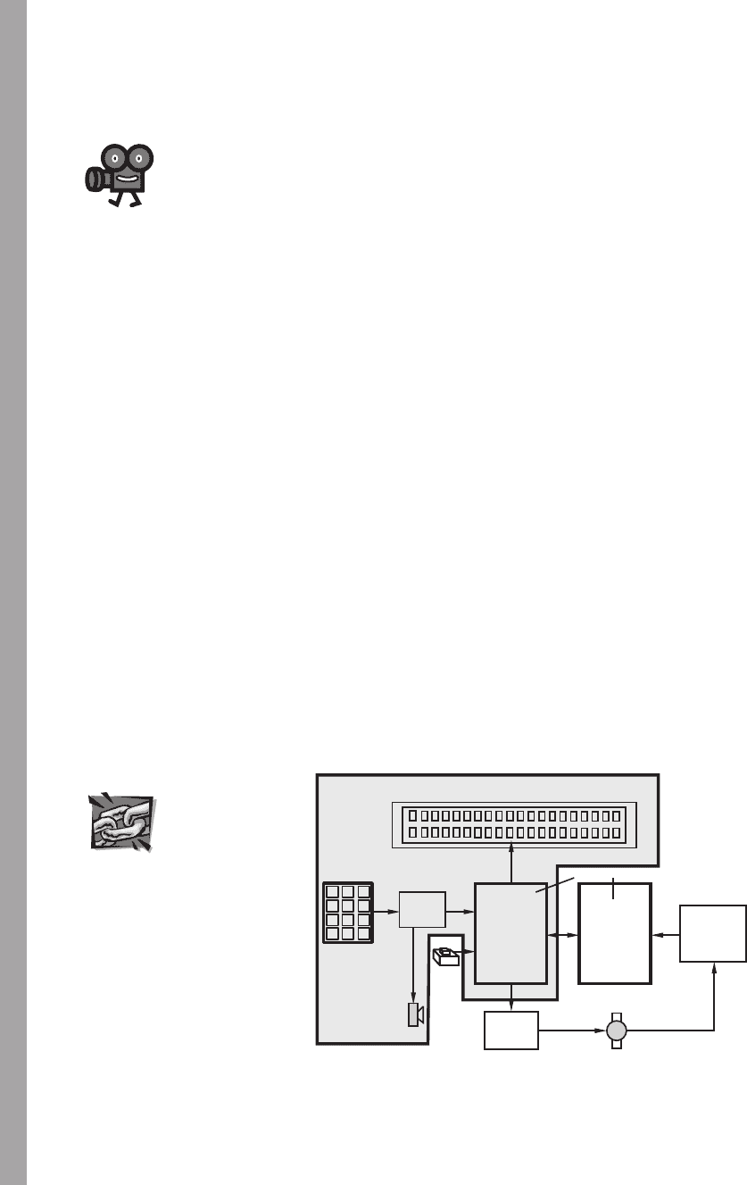
The figure that follows shows the functional diagram for Threaded Design Example C
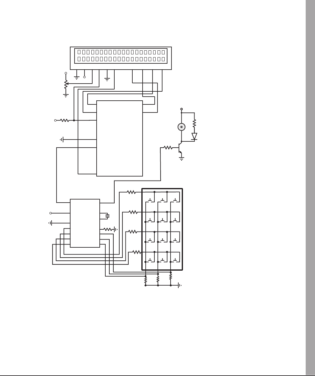
(see Section 1.3 and Video Demo 1.8), with the portion described here highlighted.
The schematic on the next page shows the components and connections for this part of
the design. A special integrated circuit available from E-Lab ( see Internet Link 7.8) called the
EDE1144 keypad decoder is used to monitor keypresses on the keypad and transmit them to
the PIC via a serial interface. Detailed information about this device can be found in the data
sheet ( see Internet Link 7.9). The EDE1144, in addition to monitoring and transmitting key-
press information, provides audio feedback to the user when a buzzer is connected as shown.
The Beep signal switches the transistor on and off, causing the buzzer to oscillate. The LED in
(continued )
alc80237_ch07_258-345.indd 303alc80237_ch07_258-345.indd 303 12/01/11 12:52 PM12/01/11 12:52 PM
Confirming Pages
microcontrollers
SLAVE
PIC
MASTER
PIC
H-bridge
driver
liquid crystal display
DC motor with
di
g
ital position encoder
quadrature
decoder
and counter
1 2 3
4 5 6
7 8 9
*
0 #
keypad
keypad
decoder
button
buzzer
304 CHAPTER 7 Microcontroller Programming and Interfacing
parallel with the buzzer provides a visual cue that a keypad button is being pressed. The LCD
is wired in the standard way shown in Figure 7.13 , allowing convenient use of the PicBasic
Pro statement: Lcdout.
Presented below is a portion of the PicBasic Pro code designed to accept input from the key-
pad and display a menu-driven user interface on the LCD. The remainder of the code will be pre-
sented in Threaded Design Example C.3. The
Serin command in the first line of the “main” loop
waits for keypress data to be transmitted from the EDE1144. The set of If statements then
dispatches the appropriate subroutine based on the user selection. Again, more details will be
shown in Threaded Design Example C.3.
Video Demo
1.8 DC motor
position and
speed controller
Internet Lin
k
7.8E-Lab, Inc.
7.9EDE1144
keypad decoder
(continued )
' Define I/O pin name
key_serial Var PORTB.0 ' keypad serial interface input
' Declare Variables
key_value Var BYTE ' code byte from the keypad
' Define constants
key_mode Con 0 ' 2400 baud mode for serial connection to
keypad.
key_1 Con $30 ' hex code for the 1-key on the keypad
key_2 Con $31 ' hex code for the 2-key on the keypad
key_3 Con $32 ' hex code for the 3-key on the keypad
' Wait for a keypad button to be pressed (i.e., polling loop)
Gosub main_menu ' display the main menu on the LCD
main:
Serin key_serial, key_mode, key_value
If (key_value = key_1) Then
Gosub position
Else
If (key_value = key_2) Then
Gosub speed
alc80237_ch07_258-345.indd 304alc80237_ch07_258-345.indd 304 12/01/11 12:52 PM12/01/11 12:52 PM
Confirming Pages
Else
If (key_value = key_3) Then
Gosub adjust_gains
Endif : Endif : Endif
Goto main ' continue polling keypad buttons
End ' end of main program
' Subroutine to display the main menu on the LCD
main_menu:
Lcdout $FE, 1, "Main Menu:"
Lcdout $FE, $C0, "1:pos. 2:speed 3:gain"
Return
20 ⫻ 2 LCD character display
V
ss
V
cc
V
ee
RS R/W E
DB4 DB5 DB6 DB7
12
3
4
5
6
11 12
13
14
5 V
5 V
20 k
pot
5 V 1 k
PIC16F88
RA1
RA0
RA7
CLKO
V
dd
RB7
RB6
RB5
RB4
1
2
3
4
5
6
7
8
9
10
11
12
13
14
15
16
17
18
RA2
RA3
RA4
RA5
V
ss
RB0
RB1
RB2
RB3
1
2
3
456
789
*
0#
1
2
3
4
5
6
7
keypad
EDE1144
XMIT
+5V
GND
R0
R1
R2
R3
Beep
Valid
OSC1
C3
C2
C1
C0
OSC2
1
3, 4, 14
2, 5
6
7
8
910
11
12
13
4.7 kΩ
4.7 kΩ
330 Ω
1 kΩ
330 Ω
15
16
18
5 V
5V
buzzer
2N2222
LED
7.7 Interfacing Common PIC Peripherals 305
alc80237_ch07_258-345.indd 305alc80237_ch07_258-345.indd 305 12/01/11 12:52 PM12/01/11 12:52 PM

Confirming Pages
306 CHAPTER 7 Microcontroller Programming and Interfacing
7.8 INTERFACING TO THE PIC
In this section, we discuss interfacing the PIC to a variety of input and output devices.
As we saw in Section 7.5.1 , each pin in the I/O ports may be configured in software
as an input or an output. In addition, the port pins may be multiplexed with other
functions to use additional features of the PIC. In this section, we examine the elec-
tronic schematics of the different input and output ports of the PIC16F84. The ports
are different combinations of TTL and CMOS devices and have voltage and current
limitations that must be considered when interfacing other devices to the PIC. You
should first refer to Section 6.11 to review details of TTL and CMOS equivalent
output circuits and open drain outputs.
We begin by looking at the architecture and function of each of the ports indi-
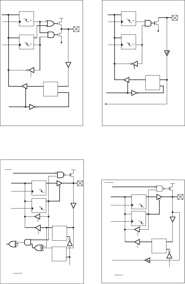
vidually. PORTA is a 5-bit-wide latch with the pins denoted by RA0 through RA4.
The block diagram for pins RA0 through RA3 is shown in Figure 7.14 , and the block
diagram for pin RA4 is shown in Figure 7.15 . The five LSBs of the TRISA register
configure the 5-bit-wide latch for input or output. Setting a TRISA bit high causes
the corresponding PORTA pin to function as an input, and the CMOS output driver
is in high impedance mode, essentially removing it from the circuit. Reading the
PORTA register accesses the pin values. Clearing a TRISA bit low causes the cor-
responding PORTA pin to serve as an output, and the data on the data latch appears
on the pin. RA4 is slightly different in that it has a Schmitt trigger input buffer that
triggers with a distinct transition even for a slowly changing and/or noisy input
(see Section 6.12.2). Also, the output configuration of RA4 is open drain, and exter-
nal components (e.g., a pull-up resistor to power) are required to complete the output
circuit.
PORTB is also bidirectional but is 8 bits wide. Its data direction register is
denoted by TRISB. Figure 7.16 shows the schematic for pins RB4 through RB7, and
Figure 7.17 shows pins RB0 through RB3. A high on any bit of the TRISB register
sets the tristate gate to the high impedance mode, which disables the output driver.
A low on any bit of the TRISB register places the contents of the data latch on the
selected output pin. Furthermore, all of the PORTB pins have weak pull-up FETs.
These FETs are controlled by a single control bit called RBPU (active low register B
pull-up). When this bit is low the FET acts like a weak pull-up resistor. This pull-up
is automatically disabled when the port pin is configured as an output. RBPU can be
set in software through the OPTION_REG special purpose register (see Section 7.6 ).
7.8.1 Digital Input to the PIC
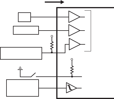
Figure 7.18 illustrates how to properly interface different types of components and
digital families of devices as inputs to the PIC. All I/O pins of the PIC that are con-
figured as inputs interface through a TTL input buffer (pins RA0 through RA3 and
pins RB0 through RB7) or Schmitt trigger input buffer (RA4). The Schmitt trigger
enhances noise immunity for a slowly changing input signal. Because an input pin
is TTL buffered in the PIC, interfacing a TTL gate or device to the PIC can be done
directly unless it is has an open-collector output. In this case, an external pull-up
resistor is required. Because the output of a 5 V powered CMOS device swings
alc80237_ch07_258-345.indd 306alc80237_ch07_258-345.indd 306 12/01/11 12:52 PM12/01/11 12:52 PM
Confirming Pages
Figure 7.16 Block diagram for pins
RB4 through RB7. (Courtesy of Microchip
Technology, Inc., Chandler, AZ)
D
O
CK
D
O
CK
O
EN
D
O
EN
D
Data bus
Data Latch
TRIS Latch
Latch
Weak
pull-up
I/O
Port
TTL
Input
Buffer
VDD
WR Port
WR TRIS
RD Port
RD TRIS
RD Port
Sot RBIF
Fromators
RB7:RB4 pins
P
RBPU*
Note 1: TRISB = ‘1’ enables weak pull-up
(RBPU* = ‘0’ in the OPTION_REG register)
2: I/O pins have diode protection to VDD and VSS
Figure 7.14 Block diagram for pins
RA0 through RA3. (Courtesy of Microchip
Technology, Inc., Chandler, AZ)
D
O
O
CK
D
O
D
O
EN
TRIS Latch
Data Latch
TTL
Input
buffer
I/O pin
V
CD
VSS
Data
bus
WR
Port
WR
TRIS
RD TRIS
RD PORT
P
N
Note: I/O pins have protection diodes to V
CD and VSS.
O
CK
Figure 7.15 Block diagram for pin
RA4. (Courtesy of Microchip Technology,
Inc., Chandler, AZ)
D
O
CK
D
O
DO
EN
TRIS Latch
Data Latch
Schmitt
Trigger
input
buffer
RA4 pin
V
SS
Data
bus
WR
PORT
WR
TRIS
RD TRIS
RD PORT
TMRO clock input
N
Note: I/O pin has protection diodes to V
SS only.
O
CK
O
Figure 7.17 Block diagram for pins
RB0 through RB3. (Courtesy of Microchip
Technology, Inc., Chandler, AZ)
D
O
CK
D
O
CK
O
EN
D
Data bus
Data Latch
RBPU*
TRIS Latch
Weak
pull-up
I/O
Port
TTL
Input
Buffer
V
CD
WR Port
WR TRIS
RD TRIS
RD Port
RD Port
RECONT
Note 1: TRISB = ‘1’ enables weak pull-up
(RBPU* = ‘0’ in the OPTION_REG register)
2: I/O pins have diode protection to V
CD and VSS.
Schmitt trigger
buffer
P
7.8 Interfacing to the PIC 307
alc80237_ch07_258-345.indd 307alc80237_ch07_258-345.indd 307 12/01/11 12:52 PM12/01/11 12:52 PM
Confirming Pages
Figure 7.18 Interface circuits for input devices
input device
PIC input pin
5 V
RB0 through RB7
weak pull-up
switch
TTL
CMOS (5 V)
slowly changing
or noisy
digital signal
RA0 through RA4
or RB0 through RB7
TTL buffers
RA4
Schmitt trigger
buffer
5 V
open-collector TTL
or open-drain CMOS
308 CHAPTER 7 Microcontroller Programming and Interfacing
nearly from 0 to 5 V, the device will drive a PIC input directly. The weak pull-up
option on pins RB0 through RB7 is useful when using mechanical switches or key-
pads for input (see Section 7.7 ). The pull-up FET maintains a 5 V input until the
switch is closed, bringing the input low. Although a TTL input usually floats high
if it is open, the FET pull-up option is useful, because it simplifies the interface
to external devices (e.g., keypad input). Finally, one must be aware of the current
specifications of the PIC input and output pins. For the PIC16F84, there is a 25 mA
sink maximum per pin with a 80 mA maximum for the entire PORTA and a 150 mA
maximum for PORTB.
7.8.2 Digital Output from the PIC
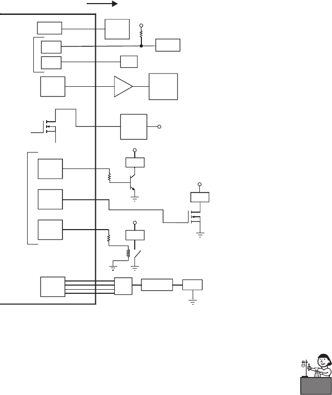
Figure 7.19 illustrates how to properly interface different types of components and
digital families of devices to outputs from the PIC. Pins RA0 through RA3 have full
CMOS output drivers, and RA4 has an open-drain output. RB0 through RB7 are
TTL buffered output drivers. A 20 mA maximum current is sourced per pin with a
50 mA maximum current sourced by the entire PORTA and a 100 mA maximum
for PORTB. CMOS outputs can drive single CMOS or TTL devices directly. TTL
outputs can drive single TTL devices directly but require a pull-up resistor to pro-
vide an adequate high-level voltage to a CMOS device. To drive multiple TTL or
CMOS devices, a buffer can be used to provide adequate current for the fan-out.
Because pin RA4 is an open-drain output, external power is required. Note that when
RA4 is high, the output pin is grounded to V
s s
, switching the small current load on,
and when RA4 is low, the output is an open circuit, switching the load off. When
interfacing transistors, power transistors, and relays, current requirements must be
considered for a proper interface. If the PIC contains a D/A converter, it can be used
with an amplifier to drive an analog load directly. Otherwise, as shown in the figure,
an external D/A IC can be used with the digital I/O ports.
alc80237_ch07_258-345.indd 308alc80237_ch07_258-345.indd 308 12/01/11 12:52 PM12/01/11 12:52 PM
Confirming Pages
Figure 7.19 Interface circuits for output devices.
output device
PIC output pin
CMOS
CMOS
or TTL
CMOS
or TTL
CMOS
or TTL
CMOS
or TTL
CMOS
or TTL
CMOS
or TTL
RA0 through RA3
RB0 through RB7
RA4
open drain
V
ss
small
current
load
load
load
V
supply
V
supply
V
supply
V
supply
load
BJT power
transistor
power
relay
n-channel
enhancement
power
MOSFET
RA0 through RA3
or RB0 through RB7
buffer
multiple
CMOS
or TTL
RA0 through RA3
or RB0 through RB7
RA0 through RA3
or RB0 through RB7
D/A
amplifier load
5 V
CMOS
TTL
TTL
TTL
7.9 Method to Design a Microcontroller-Based System 309
As an example of using a PIC digital output to control a high-current load, a
power MOSFET is used to switch power to a DC motor in Lab Exercise 11. The
voltage is actually switched on and off very quickly. To vary the speed of the motor,
the percentage of on and off times (i.e., the duty cycle ) is changed. This is called
pulse-width modulation (see Section 10.5.3 for more information).
7.9 METHOD TO DESIGN A
MICROCONTROLLER-BASED SYSTEM
In all the examples presented in this chapter, the problems were simple, yielding
short solutions to illustrate fundamental coding structures. Also, many design deci-
sions were included as part of the problem statements. In conceiving an altogether
new design, it is advisable to follow a methodical design process that will take you
from the initial problem statement to a programmed microcontroller that can be
embedded in application hardware. A design procedure we recommend follows.
To illustrate the application of the procedure, we apply it to the problem presented
Lab Exercise
Lab 11Pulse-
width-modulation
motor speed
control with
a PIC
alc80237_ch07_258-345.indd 309alc80237_ch07_258-345.indd 309 12/01/11 12:52 PM12/01/11 12:52 PM

Confirming Pages
310 CHAPTER 7 Microcontroller Programming and Interfacing
in Design Example 7.2. Lab Exercise 11 also shows the procedure applied to an
example.
1 . Define the problem. State the problem in words to explain the desired func-
tionality of the device (i.e., what is the device supposed to do?).
2. Draw a functional diagram Draw a block diagram that illustrates all of
the major components of the design and shows how they are interconnected.
Each component can be shown as a square with a descriptive label inside or,
preferably, as a pictorial representation (e.g., a clipart image or photograph).
Use single lines to connect the components (regardless of the number of wires
involved), and include arrowheads to indicate the direction of signal flow.
3. Identify I/O requirements. List the types of inputs and outputs required and
what functions need to be performed by the microcontroller. You need to iden-
tify the number of each type of I/O line you require, including digital inputs,
digital outputs, A/D converters, D/A converters, and serial ports.
4. Select appropriate microcontroller models. Based on the types and number
of inputs and outputs identified in the previous step, choose one or more micro-
controllers that have sufficient on-chip resources. Another factor that influences
this choice is the anticipated amount of program and data memory required.
If the program is very complex and the application requires significant data
storage, then choose a microcontroller with ample memory capacity. If multiple
PICs are required (due to I/O and/or memory constraints), the PICs can
communicate with each other through I/O lines by using simple handshaking
(e.g., wait for a signal from another PIC to go high before doing something and
then send another signal back when done) or PicBasic Pro’s Serout and Serin
statements for serial communication (e.g., to share data between the PICs).
Refer to manufacturer literature for a list of available models and capacities.
Information for Microchip’s entire line of PIC microcontroller products can be
found online (see Internet link 7.10, which points to the line of reprogrammable
flash-memory microcontrollers listed at www.microchip.com ).
5. Identify necessary interface circuits. Refer to the microcontroller input and
output circuit specifications and use the information in Section 7.8 to design
appropriate interface circuitry utilizing pull-up resistors, buffers, transistors,
relays, and amplifiers where required. Also, in cases that require many digital
I/O lines, where the PIC(s) selected do not provide enough I/O pins, there are
ways to interface to a large number of lines with a smaller set of pins. One
approach is to use shift registers (e.g., the 74164, 74594, or 74595 for output,
and the 74165 or 74597 for input), where a small set of PIC I/O pins (two for
the nonlatched type and three for the latched type) can be used to transmit
bits serially to or from an 8-bit register, providing eight lines of I/O. Another
alternative when expanding your I/O capability is to use a device providing
multiplexed programmable I/O ports (e.g., the Intel 82C55A programmable
peripheral interface, or PPI). This type of device allows one I/O port to switch
access among several I/O ports. With Intel’s 82C55A, 5 control lines and 8
data lines provide access to 24 lines of general purpose, user-configurable I/O.
Internet Lin
k
7.10Microchip
PIC flash product
line
alc80237_ch07_258-345.indd 310alc80237_ch07_258-345.indd 310 12/01/11 12:52 PM12/01/11 12:52 PM
