Alciatore D.G., Histand M.B. Introduction to Mechatronics and Measurement Systems
Подождите немного. Документ загружается.

Confirming Pages
7.4 Programming a PIC 271
Assembly Language Programming Example
EXAMPLE 7.2
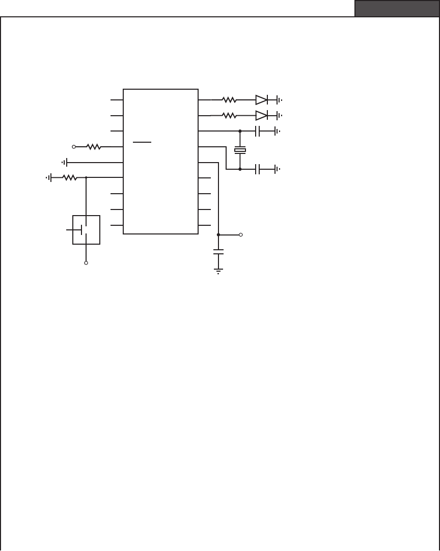
The purpose of this example is to write an assembly language program that will turn on an
LED when the user presses a pushbutton switch. When the switch is released, the LED is to
turn off. After the switch is pressed and released a specified number of times, a second LED is
to turn on and stay lit. The hardware required for this example is shown in the following figure:
PIC16F84
RA2
RA3
RA4
V
ss
RB0
RB1
RB2
RB3
RA1
RA0
OSC1
OSC2
V
dd
RB7
RB6
RB5
RB4
1
2
3
4
5
6
7
8
9
10
11
12
13
14
15
16
17
18
5 V
22 pF
22 pF
4 MHz
1 k
1 k
5 V
0.1 μF
330
LED2
330
LED1
bounce-free
normally open
pushbutton switch
NO
5 V
MCLR
The pushbutton switch is assumed to be bounce-free, implying that when it is pressed
and then released, a single pulse is produced (the signal goes high when it is pressed and
goes low when it is released).
Assembly language code that will accomplish the desired task follows the text below.
A remark or comment can be inserted anywhere in a program by preceding it with a semi-
colon (;). Comments are used to clarify the associated code. The assembler ignores com-
ments when generating the hex machine code. The first four active lines ( list . . . target ) are
assembler directives that designate the processor and define constants that can be used in the
remaining code. Defining constants (with the equ directive) at the beginning of the program
is a good idea because the names, rather than hex numbers, are easier to read and understand
in the code and because the numbers can be conveniently located and edited later. Assembly
language constants such as addresses and values are written in hexadecimal, denoted with
a 0x prefix.
The next two lines of code, starting with movlw, move the literal constant target into
the W register and then from the W register into the count address location in memory. The
target value (0x05) will be decremented until it reaches 0x00. The next section of code
initializes the special function registers PORTA and TRISA to allow output to pins RA0
and RA1, which drive the LEDs. These registers are located in different banks of memory,
hence the need for the bsf and bcf statements in the program. All capitalized words in the
program are constant addresses or values predefined in the processor-dependent include
(continued )
alc80237_ch07_258-345.indd 271alc80237_ch07_258-345.indd 271 12/01/11 12:52 PM12/01/11 12:52 PM

Confirming Pages
272 CHAPTER 7 Microcontroller Programming and Interfacing
file (p16f84.inc). The function of the TRISA register is discussed more later; but by clear-
ing the bits in the register, the PORTA pins are configured as outputs.
The main loop uses the btfss (bit test in file register; skip the next instruction if the
bit is set) and btfsc (bit test in file register; skip the next instruction if the bit is clear)
statements to test the state of the signal on pin RB0. The tests are done continually within
loops created by the goto statements. The words begin and wait are statement labels used
as targets for the goto loops. When the switch is pressed, the state goes high and the
statement btfss skips the goto begin instruction; then LED1 turns on. When the switch is
released, pin RB0 goes low and the statement btfsc skips the goto wait instruction; then
LED1 turns off.
After the switch is released and LED1 turns off, the statement decfsz (decrement file
register; skip the next instruction if the count is 0) executes. The decfsz decrements the
count value by 1. If the count value is not yet 0, goto begin executes and control shifts
back to the label begin. This resumes execution at the beginning of the main loop, wait-
ing for the next switch press. However, when the count value reaches 0, decfsz skips the
goto begin statement and LED2 is turned on. The last goto begin statement causes the
program to again jump back to the beginning of the main loop to wait for another button
press.
(continued )
; bcount.asm (program file name)
; Program to turn on an LED every time a pushbutton switch is pressed and turn on
; a second LED once it has been pressed a specified number of times
; I/O:
; RB0: bounce-free pushbutton switch (1:pressed, 0:not pressed)
; RA0: count LED (first LED)
; RA1: target LED (second LED)
; Define the processor being used
list p 16f84
include <p16F84.inc>
; Define the count variable location and the initial count-down value
count equ 0x0c ; address of count-down variable
target equ 0x05 ; number of presses required
; Initialize the counter to the target number of presses
movlw target ; move the count-down value into the
; W register
movwf count ; move the W register into the count memory
; location
; Initialize PORTA for output and make sure the LEDs are off
bcf STATUS, RP0 ; select bank 0
clrf PORTA ; initialize all pin values to 0
bsf STATUS, RP0 ; select bank 1
clrf TRISA ; designate all PORTA pins as outputs
bcf STATUS, RP0 ; select bank 0
alc80237_ch07_258-345.indd 272alc80237_ch07_258-345.indd 272 12/01/11 12:52 PM12/01/11 12:52 PM
Confirming Pages
7.4 Programming a PIC 273
; Main program loop
begin
; Wait for the pushbutton switch to be pressed
btfss PORTB, 0
goto begin
; Turn on the count LED1
bsf PORTA, 0
wait
; Wait for the pushbutton switch to be released
btfsc PORTB, 0
goto wait
; Turn off the count LED1
bcf PORTA, 0
; Decrement the press counter and check for 0
decfsz count, 1
goto begin ; continue if count-down is still > 0
; Turn on the target LED2
bsf PORTA, 1
goto begin ; return to the beginning of the main loop
end ; end of instructions
■ CLASS DISCUSSION ITEM 7.2
Decrement Past 0
In Example 7.2 , the decfsz statement is used to count down from 5 to 0. When 0
(0x00) is decremented, the resulting value at address count will be 255 (0xFF), then
254 (0xFE), and so forth. What effect, if any, does this have on the operation of the
code and the LED display? To have the program continue its normal operation after
the decrement to zero, what code would you need to add?
Learning to program in assembly language can be very difficult at first and may
result in errors that are difficult to debug. Fortunately, high-level language compilers
are available that allow us to program a PIC at a more user-friendly level. The par-
ticular programming language we discuss in the remainder of the chapter is PicBasic
Pro. The compiler for PicBasic Pro is available from microEngineering Labs, Inc.
(see Internet Link 7.4, which points to www.melabs.com ). PicBasic Pro is much eas-
ier to learn and use than assembly language. It provides easy access to all of the PIC
capabilities and provides a rich set of advanced functions and features to support var-
ious applications. PicBasic Pro is also closely compatible with the BASIC language
Internet Lin
k
7.4micro Engi-
neering Labs
alc80237_ch07_258-345.indd 273alc80237_ch07_258-345.indd 273 12/01/11 12:52 PM12/01/11 12:52 PM

Confirming Pages
274 CHAPTER 7 Microcontroller Programming and Interfacing
used to control Basic Stamp minicontrollers (Parallax, Inc., Rocklin, CA), which are
popular development boards that utilize the PIC microcontroller.
For additional information on the PIC and related products, see Internet Link
7.5. This site contains many useful links to manufacturers and other useful web
pages that provide resources and information on support literature, useful accesso-
ries, and PicBasic Pro.
7.5 PICBASIC PRO
PIC programs can be written in a form of BASIC called PicBasic Pro. The PicBa-
sic Pro complier can compile these programs, producing their assembly language
equivalents, and this assembly code can then be converted to hexadecimal machine
code (hex code) that can be downloaded directly to the PIC flash EEPROM through
a programming device attached to a PC. Once loaded, the program begins to execute
when power is applied to the PIC if the necessary additional components, such as
those shown in Figure 7.4 , are connected properly.
We do not intend to cover all aspects of PicBasic Pro programming. Instead,
we present an introduction to some of the basic programming principles, provide
a brief summary of the statements, and then provide some examples. The PicBasic
Pro Complier manual available online (see Internet Link 7.6) is a necessary supple-
ment to this chapter if you need to solve problems requiring more functionality than
the examples we present here. If you have not used a programming language such
as BASIC, C, C , or FORTRAN, then Section 7.5.1 may be challenging for you.
Even if this the case, as you read through the examples that follow, the concepts
should become clearer.
7.5.1 PicBasic Pro Programming Fundamentals
To illustrate the fundamentals of PicBasic Pro, we start with a very simple example.
The goal is to write a program to turn on an LED for a second, then turn it off for
a second, repeating for as long as power is applied to the circuit. The code for this
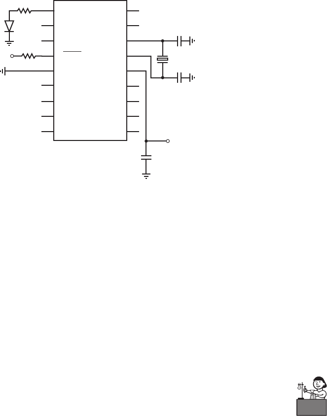
program, called flash.bas, follows. The hardware required is shown in Figure 7.7 .
Pin RA2 is used as an output to source current to an LED through a current-limiting
resistor. The first two lines in the program are comments that identify the program
and its purpose. Comment lines must begin with an apostrophe. On any line, infor-
mation on the right side of an apostrophe is treated as a comment and ignored by the
compiler. The label loop allows the program to return control to this label at a later
time using the Goto command. The statement High PORTA.2 causes pin RA2 to go
high and the LED turns on. The Pause command delays execution of the next line of
code a given number of milliseconds (in this case, 1000, which corresponds to 1000
milliseconds or 1 second). The statement Low PORTA.2 causes pin RA2 to go low,
turning the LED off. The next Pause causes a 1 sec delay before executing the next
line. The Goto loop statement returns control to the program line labeled loop, and
the program continues indefinitely. The End statement on the last line of the program
terminates execution. In this example, the loop continues until power is removed,
Internet Lin
k
7.6PicBasic
Pro manual
Internet Lin
k
7.5Microchip
PIC microcontroller
resources
alc80237_ch07_258-345.indd 274alc80237_ch07_258-345.indd 274 12/01/11 12:52 PM12/01/11 12:52 PM
Confirming Pages
Figure 7.7 Circuit schematic for the flash.bas example.
PIC16F84
RA2
RA3
RA4
V
ss
RB0
RB1
RB2
RB3
RA1
RA0
OSC1
OSC2
V
dd
RB7
RB6
RB5
RB4
1
2
3
4
5
6
7
8
9
10
11
12
13
14
15
16
17
18
5 V
22 pF
22 pF
4 MHz
1 k
5 V
0.1 μF
330
LED
MCLR
7.5 Picbasic Pro 275
and the End statement is never reached. However, to be safe you should always ter-
minate a program with an End statement.
Lab Exercise 9 explores how to implement simple programs like flash.bas
above. The exercise includes steps for wiring circuits to a PIC, entering and compil-
ing PicBasic Pro programs, and downloading executable code from a PC to the flash
memory on the PIC.
As illustrated in the simple flash.bas example, PicBasic Pro programs consist
of a sequence of program statements that are executed one after another. The pro-
grammer must be familiar with the syntax of PicBasic Pro, but it will be easier to
learn and debug than assembly language programs. Comments, any text preceded by
an apostrophe, can be placed anywhere in the program to help explain the purpose
of specific lines of the code. Any user-defined labels, variable names, or constant
names are called identifiers (e.g., loop in the preceding example). You can use any
combination of characters for these identifiers, provided they do not start with a num-
ber. Also, identifiers must be different from all the words reserved by PicBasic Pro
Lab Exercise
Lab 9Program-
ming a PIC
microcontroller—
part I
' flash.bas
' Example program to flash an LED once every two seconds
loop: High PORTA.2 ' turn on LED connected to pin RA2
Pause 1000 ' delay for one second (1000 ms)
Low PORTA.2 ' turn off LED connected to pin RA2
Pause 1000 ' delay for one second (1000 ms)
Goto loop ' go back to label "loop" and repeat
' indefinitely
End
alc80237_ch07_258-345.indd 275alc80237_ch07_258-345.indd 275 12/01/11 12:52 PM12/01/11 12:52 PM
Confirming Pages
276 CHAPTER 7 Microcontroller Programming and Interfacing
(e.g., keywords like High and Low ). Identifiers may be any length, but PicBasic Pro
ignores all the characters after the first 32. PicBasic Pro is not case sensitive so it does
not matter whether or not letters are capitalized. Therefore, any combination of lower
or upper case letters can be used for identifiers, including labels, variables, state-
ments, and register or bit references. For example, to PicBasic Pro, High is equivalent
to HIGH or high. However, when writing code, it is best to use a consistent pattern
that helps make the program more readable. In the examples presented in this chap-
ter, all variables and labels are written in lower case, all keywords in statements are
written with an initial capital, and all registers and constants are written in upper case.
In some applications, you need to store a value for later use in the program (e.g.,
a counter that is incremented each time a pushbutton switch is pressed). PicBasic Pro
lets you create variables for this purpose. The syntax for creating a variable is
name Var type (7.1)
where name is the identifier to be used to refer to the variable and type describes
the type and corresponding data storage size of the variable. The type can be BIT
to store a single bit of information (0 or 1), BYTE to store an 8-bit positive integer
that can range from 0 to 255 (2
8
1), or WORD to store a 2-byte (16-bit) positive
integer that can range from 0 to 65,535 (2
16
1). The following lines are examples
of variable declarations and assignment statements that store values in variables:
my_bit Var BIT
my_byte Var BYTE
my_bit 0
my_byte 187
The Va r keyword can also be used to give identifier names to I/O pins or to bits
within a byte variable using the following syntax:
name Var byte.bit (7.2)
For example,
led Var PORTB.0
lsb Var my_byte.0
would designate led as the state of pin RB0 and lsb as bit 0 of byte variable my_byte.
Another type of variable is an array, which can be used to store a set or vector
of numbers. The syntax for declaring an array is
name Var type[size] (7.3)
where type defines the storage type (BIT, BYTE, or WORD) and size indicates the
number of elements in the array. A particular element in an array can be accessed or
referenced with the following syntax:
name[i] (7.4)
where i is the index of the element being referenced. The elements are numbered
from 0 to size–1. For example, values Var byte[5] would define an array of 5 bytes,
alc80237_ch07_258-345.indd 276alc80237_ch07_258-345.indd 276 12/01/11 12:52 PM12/01/11 12:52 PM
Confirming Pages
7.5 Picbasic Pro 277
and the elements of the array would be values[0], values[1], values[2], values[3],
and values[4].
Constants can be given names in a program using the same syntax as that used
for variables (Equation 7.1) by replacing the Va r keyword with Con and by replac-
ing the type keyword by a constant value. When specifying values in a program, the
prefix $ denotes a hexadecimal value and the prefix % denotes a binary value. If
there is no prefix, the number is assumed to be a decimal value. For example, with
the following variable and constant definitions, all of the assignment statements that
follow are equivalent:
number Var BYTE
CONSTANT Con 23
number 23
number CONSTANT
number %10111
number $17
Normally, constants and results of calculations are assumed to be unsigned (i.e.,
zero or positive), but certain functions, such as Sin and Cos, use a different byte for-
mat, where the MSB is used to represent the sign of the number. In this case, the byte
can take on values between 127 and 127. Some of the fundamental expressions
using mathematical operators and functions available in PicBasic Pro are listed
in Table 7.3 . See other operators and functions, more details, and examples in the
PicBasic Pro Compiler manual.
Table 7.3 Selected PicBasic Pro math operators and functions
Math operator
or function Description
A B Add A and B
A B Subtract B from A
A * B Multiply A and B
A / B Divide A by B
A // B
Return the remainder (modulo) of the
division of B into A
A << n Shift A n bits to the left
A >> n Shift A n bits to the right
COS A Return the cosine of A
A MAX B Return the maximum of A and B
A MIN B Return the minimum of A and B
SIN A Return the sine of A
SQR A Return the square root of A
A & B Return the bitwise AND of A and B
A | B Return the bitwise OR of A and B
A ^ B Return the bitwise Exclusive OR of A and B
~A Return the bitwise NOT of A
alc80237_ch07_258-345.indd 277alc80237_ch07_258-345.indd 277 12/01/11 12:52 PM12/01/11 12:52 PM

Confirming Pages
278 CHAPTER 7 Microcontroller Programming and Interfacing
When doing integer arithmetic with fixed-bit-length variables (e.g., BYTE and
WORD), one must check for truncation and overflow errors. As pointed out above,
each variable type can only store numbers within a certain range (e.g., 0 to 255 for a
BYTE variable). If you try to assign an expression to a variable, and the expression’s
value exceeds the maximum value allowed for the variable, an error will result. This
is called overflow. Truncation occurs with integer division. If an integer division
calculation results in a fraction, the remainder of the division (the decimal portion) is
discarded. Sometimes the effects of truncation can be minimized or avoided by rear-
ranging terms in an expression so divisions are performed at strategic points. These
principles are presented in detail, with examples, in Lab Exercise 11 .
There is a collection of PicBasic Pro statements that allow you to read, write,
and process inputs from and outputs to the I/O port pins. To refer to an I/O pin, you
use the following syntax:
port_name.bit (7.5)
where port_name is the name of the port (PORTA or PORTB) and bit is the bit
location specified as a number between 0 and 7. For example, to refer to pin RB1,
you would use the expression PORTB.1. When a bit is configured as an output, the
output value (0 or 1) on the pin can be set with a simple assignment statement (e.g.,
PORTB. 1 1 ). When a bit is configured as an input, the value on the pin (0 or 1) can
be read by referencing the bit directly (e.g., value PORTA. 2). All of the bits within
a port can be set at one time using an assignment statement of the following form:
port_name constant (7.6)
where constant is a number between 0 and 255 expressed in binary, hexadecimal, or
decimal. For example, PORTA %00010001 sets the PORTA.0 and PORTA.4 bits
to 1, and sets all other bits to 0. Because the three most significant bits in PORTA are
not used, they need not be specified (i.e., PORTA %10001 is equivalent and more
appropriate).
The I/O status of the PORTA and PORTB bits are configured in two special
registers called TRISA and TRISB. The prefix TRIS is used to indicate that tristate
gates control whether or not a particular pin provides an input or an output. The
input and output circuits for PORTA and PROTB on the PIC16F84 are presented
in Section 7.8 , where we deal with interfacing. When a TRIS register bit is set
high (1), the corresponding PORT bit is considered an input, and when the TRIS
bit is low (0), the corresponding PORT bit is considered an output. For example,
TRISB %01110000 would designate pins RB4, RB5, and RB6 as inputs and the
other PORTB pins as outputs. At power-up, all TRIS register bits are set to 1 (i.e.,
TRISA and TRISB are both set to $FF or %11111111), so all pins in PORTA and
PORTB are treated as inputs by default. You must redefine them if necessary for
your application, in the initialization statements in your program.
The port bit access syntax described by Equation 7.5 can also be used to access
individual bits in byte variables. For example, given the following declarations,
my_byte Var byte
my_array Var byte[10]
Lab Exercise
Lab 11Pulse-
width-modulation
motor speed
control with a PIC
alc80237_ch07_258-345.indd 278alc80237_ch07_258-345.indd 278 12/01/11 12:52 PM12/01/11 12:52 PM
Confirming Pages
7.5 Picbasic Pro 279
my_byte. 3 1 would set bit 3 in my_byte to 1 and my_array[9]. 7 0 would set the
MSB of the last element of my_array to 0. All bits within a variable can be set by
assigning a value or expression to the variable with an assignment statement:
variable expression (7.7)
For example,
my_byte 231
my_array[2] my_byte 12
Two important features in any programming language are statements to perform
logical comparisons and statements to branch, loop, and iterate. In PicBasic Pro, logic
is executed within an If . . . Then . . . Else . . . statement construct, where a logical
comparison is made and if the result of the comparison is true, then the statements
after Then are executed; otherwise, the statements after Else are executed. PicBasic
Pro supports the logical comparison operators listed in Table 7.4 . The keywords
And, Or, Xor (exclusive Or), and Not can also be used in conjunction with parenthe-
ses to create general Boolean expressions for use in logical comparisons. Example 7.3
and other examples to follow illustrate use of logical expressions.
Table 7.4 PicBasic Pro logical
comparison operators
Operator Description
or equal
<> or ! not equal
< less than
> greater than
<
less than or equal to
>
greater than or equal to
The following PicBasic Pro statement turns on a motor controlled by a transistor connected
to pin RA0 when the state of a switch connected to pin RB0 is high or when the state of a
switch connected to pin RB1 is low, and when a byte variable count has a value less than or
equal to 10:
If (((PORTB.0 1) OR (PORTB.1 0)) And (count
<
10)) Then
High PORTA.0
A PicBasic Pro Boolean Expression
EXAMPLE 7.3
The simplest form of looping is to use a statement label with a goto statement as
illustrated earlier in the flash.bas example. PicBasic Pro also provides For . . . Next
and While . . . Wend statement structures to perform looping and iteration. These
constructs are demonstrated in examples through the remainder of the chapter.
alc80237_ch07_258-345.indd 279alc80237_ch07_258-345.indd 279 12/01/11 12:52 PM12/01/11 12:52 PM

Confirming Pages
280 CHAPTER 7 Microcontroller Programming and Interfacing
Table 7.5 PicBasic Pro statement summary
Statement Description
@ assembly statement Insert one line of assembly language code
ADCIN channel, var Read the on-chip analog to digital converter (if there
is one)
ASM . . . ENDASM Insert an assembly language code section consisting
of one or more statements
BRANCH index, [label1{, label2, . . .}] Computed goto that jumps to a label based on index
BRANCHL index, [label1{, label2, . . .}] Branch to a label that can be outside of the current
page of code memory (for PICs with more than 2 k
of program ROM)
BUTTON pin, down_state, auto_repeat_delay,
auto_repeat_rate, countdown_variable,
action_state, label
Read the state of a pin and perform debounce (by use
of a delay) and autorepeat (if used within a loop)
CALL assembly_label Call an assembly language subroutine
CLEAR Zero all variables
CLEARWDT Clear the watch-dog timer
COUNT pin, period, var Count the number of pulses occurring on a pin during
a period
DATA {@ location,} constant1
{, constant2, . . .}
Define initial contents of the on-chip EEPROM
(same as the EEPROM statement)
DEBUG item1{, item2, . . .} Asynchronous serial output to a pin at a fixed baud rate
DEBUGIN {timeout, label,} [item1
{, item2, . . .}]
Asynchronous serial input from a pin at a fixed baud
rate
DISABLE Disable ON INTERRUPT and ON DEBUG
processing
DISABLE DEBUG Disable ON DEBUG processing
DISABLE INTERRUPT Disable ON INTERRUPT processing
DTMFOUT pin, {on_ms, off_ms,} [tone1
{, tone2, . . .}]
Produce touch tones on a pin
{EEPROM {@ location,} constant1
{, constant2, . . .}}
Define initial contents of on-chip EEPROM (same as
the DATA statement)
ENABLE Enable ON INTERRUPT and ON DEBUG processing
ENABLE DEBUG Enable ON DEBUG processing
ENABLE INTERRUPT Enable ON INTERRUPT processing
END Stop execution and enter low power mode
Table 7.5 lists all of the PicBasic Pro statements with corresponding descrip-
tions. Complete descriptions and examples of the statements and their associated
parameters and variables can be found in the PicBasic Pro Compiler manual avail-
able online at microEngineering, Inc.’s website (see Internet Link 7.6). In Table 7.5 ,
the keywords are capitalized, and the parameters or variables that follow the key-
words are shown in lower case. Also, any statement parameters enclosed within
curly brackets ({. . .}) are optional. All the features and operators just presented and
all the statements listed in the table are built from the limited set of assembly lan-
guage instructions given in Table 7.2 . PicBasic Pro eliminates the cryptic assembly
language details for you and provides a high-level, more user-friendly language.
Internet Lin
k
7.6PicBasic Pro
manual (online,
PDF file)
alc80237_ch07_258-345.indd 280alc80237_ch07_258-345.indd 280 12/01/11 12:52 PM12/01/11 12:52 PM
