Alciatore D.G., Histand M.B. Introduction to Mechatronics and Measurement Systems
Подождите немного. Документ загружается.


Confirming Pages
7.5 Picbasic Pro 291
' Declare variables
number var BYTE ' digit to be displayed (value assumed to be from 0
' to 9)
pins var BYTE[10] ' an array of 10 bytes used to store the 7-segment
' display codes for each digit
' Initialize I/O pins
TRISB = %00000000 ' designate all PORTB pins as outputs (although, pin 7 is
' not used)
' Segment codes for each digit where a 0 implies the segment is on and a 1 implies
' it is off, because the PIC sinks current from the LED display
' %gfedcba display
pins[0] = %1000000 ' 0
pins[1] = %1111001 ' 1
pins[2] = %0100100 ' 2
pins[3] = %0110000 ' 3
pins[4] = %0011001 ' 4
pins[5] = %0010010 ' 5
pins[6] = %0000011 ' 6
pins[7] = %1111000 ' 7
pins[8] = %0000000 ' 8
pins[9] = %0011000 ' 9
(continued )
The remainder of your code might consist of a polling loop that needs to update the digital
display periodically. A subroutine can be used to accomplish this. Subroutines are blocks
of code to perform specialized functions that may need to be executed in numerous places
within your program. Using the byte variable number declared in the code, the following
subroutine could be used to display the value stored in the variable:
' Subroutine to display a digit on a 7-segment LED display. The value of the
' digit must be stored in a byte variable called "number." The value is assumed
' to be less than 10; otherwise, all segments are turned off to indicate an error.
display_digit:
If (number < 10) Then
PORTB = pins[number] ' display the digit
Else
PORTB = %1111111 ' turn off all 7 segments
Endif
Return
A number can be displayed at any point in your program by assigning the value to the
variable number and calling the subroutine. For example, the following statements would
display the digit 8:
number 8
Gosub display_digit
The solution just presented above requires seven output pins. Because the PIC16F84 has a
total of only 13 I/O pins, this could limit the addition of other I/O functions in your design.
alc80237_ch07_258-345.indd 291alc80237_ch07_258-345.indd 291 12/01/11 12:52 PM12/01/11 12:52 PM

Confirming Pages
292 CHAPTER 7 Microcontroller Programming and Interfacing
An alternative design that requires fewer output pins uses a seven-segment decoder IC (e.g.,
7447). Here, only four I/O pins are required as shown next:
RB0
RB1
RB2
RB3
6
7
8
9
7447
decoder
A
B
C
D
a
b
c
d
e
f
g
a
b
c
d
e
f
g
5 V
7x
current-limited
7-se
g
ment LED displa
y
For this case, the pins array is not required, and only pins RB0 through RB3 require initial-
ization as outputs. The subroutine would change to
(continued)
display_digit:
If (number < 10) Then
PORTB = (PORTB & $F0) | number ' display the digit
Else
PORTB = (PORTB & $F0) | $F ' turn off all segments
Endif
Return
The assignment statement for PORTB uses a logic mask to retain the four MSBs of
PORTB, which may have been independently set by other program statements for other
functions, and to assign the binary equivalent of number to the four LSBs that are output to
the seven-segment display driver. A logic mask is a bit string used to protect selected bits in
a binary number from change while allowing others to change. The bitwise AND (&) and
OR (|) operators are used to help accomplish the mask operation. The term PORTB & $F0
retains the four MSBs while clearing the four LSBs with zeros. For example, if PORTB’s
current value is %11011001, then PORTB & $F0 yields the following result:
%11011001 (PORTB)
&
%11110000 ($F0)
%11010000 (PORTB & $F0)
By OR-ing this result with number, the four LSBs are replaced by the corresponding binary
value of number. For example, if the current value of number is 7 (%0111), then (PORTB &
$F0) | number would yield the following result:
%11010000 (PORTB & $F0)
|
%00000111 (number)
%11010111 ((PORTB & $F0) | number)
As you can see, the four MSBs of PORTB remain unchanged, and the four LSBs have
changed to the binary value of number.
alc80237_ch07_258-345.indd 292alc80237_ch07_258-345.indd 292 12/01/11 12:52 PM12/01/11 12:52 PM

Confirming Pages
7.5 Picbasic Pro 293
The $F (15) in the Else clause is the input value required by the decoder IC to blank all
seven segments.
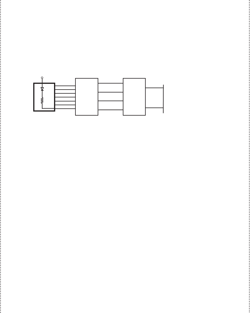
If you lack the luxury of even four I/O pins in your design but still wish to display a
digit, another alternative is to use a 7490 decade counter IC with reset and count inputs. The
reset input is assumed to have positive logic, so when the line goes high, the counter is reset
to 0. The count input is edge triggered, and in this example it does not matter if it is positive
or negative edge-triggered. Only two PIC I/O pins are required to drive this alternative as
shown next:
RB0
RB1
6
7
7447
decoder
A
B
C
D
a
b
c
d
e
f
g
7490
decade
counter
A
B
C
D
reset
count
a
b
c
d
e
f
g
5 V
7x
current-limited
7-se
g
ment LED displa
y
In this case, only pins RB0 and RB1 need be initialized as outputs, and a new counter
variable ( i ) has to be declared for use in the subroutine. Also, two pin assignments can be
made as follows:
(continued )
i Var BYTE ' counter variable used in FOR loop
reset Var PORTB.0 ' signal to reset the counter to 0
count Var PORTB.1 ' signal to increment the counter by 1
The subroutine would change to
display_digit:
Pulsout reset, 1 ' send a full pulse to reset the counter
' to zero
If (number < 10) Then
' Increment the counter "number" times to display the appropriate
' digit
For i = 1 To number
Pulsout count, 1 ' send a full pulse to increment the
' counter
Next i
Else
' Increment the counter 15 times to clear the display (all segments
' off)
For i = 1 To 15
Pulsout count, 1 ' send a full pulse to increment the
' counter
Next i
Endif
Return
alc80237_ch07_258-345.indd 293alc80237_ch07_258-345.indd 293 12/01/11 12:52 PM12/01/11 12:52 PM

Confirming Pages
294 CHAPTER 7 Microcontroller Programming and Interfacing
Here, the PicBasic Pro statement Pulsout is used to send a pulse to each of the control
pins. The syntax of this command is
Pulsout pin, period
where pin is the pin identifier (e.g., PORTB.0) and period is the length of the pulse in tens of
microseconds. The pulses generated by the code above are 10 microseconds wide.
In this example, the last two alternatives require additional components (the decoder
and counter ICs). If the physical size of the design is no constraint and an objective is to
minimize cost by not having to use an additional PIC16F84 or an alternative PIC with more
I/O pins, then one of the latter alternatives might be attractive.
(concluded )
■ CLASS DISCUSSION ITEM 7.9
Fast Counting
In the third option presented in Design Example 7.1 , the counter was incremented
the appropriate number of times to display the desired decimal value on the display.
Do you think that this counting will be detectable on the display? Why or why not?
Lab Exercise 10 shows how to wire components and write software to create
some of the functionality presented in Design Example 7.1. The exercise expands
upon the design example functionality by providing a display of all hexadecimal dig-
its from 0 to F. Video Demos 7.2 and 7.3 show two different designs explored in Lab
Exercise 10 . The first solution uses a 555 timer circuit with data latches to debounce
pushbutton switch input signals, and the second solution deals with switch bounce in
software using delays.
7.6 USING INTERRUPTS
The program to solve the security system problem presented in Example 7.9 uses
a method called polling, where the program includes a check of the sensor inputs
within a loop to update the output accordingly. Program flow is easy to under-
stand, because all processing takes place within the main program loop. The loop
repeats as long as the microcontroller is powered. For more complex applications,
polling may not be suitable, because the loop may take too long to execute. In a
long loop, the inputs may not be checked often enough. An alternative approach
is to use an interrupt. In an interrupt-driven program, some inputs are connected
to special input lines, designated as interrupts. When one or more of these lines
changes level, the microcontroller temporarily suspends normal program execu-
tion while the change is acted on by a subprogram or function called an interrupt
service routine. At the end of the service routine, control is returned to the main
program at the point where the interrupt occurred. Because polling is easier to
Video Demo
7.2Hexadec-
imal counter
using a 555 timer
and data flip-
flops for switch
debounce
7.3Hexadec-
imal counter
with software
debounce
Lab Exercise
Lab 10
Programming a PIC
microcontroller—
part II
alc80237_ch07_258-345.indd 294alc80237_ch07_258-345.indd 294 12/01/11 12:52 PM12/01/11 12:52 PM

Confirming Pages
7.6 Using Interrupts 295
implement, it is preferred over interrupts, as long as the polling loop can run fast
enough.
To detect interrupts, two specific registers on the PIC must be initialized cor-
rectly. These are the option register ( OPTION_REG ) and the interrupt control reg-
ister ( INTCON ). The definition for each bit in the first register (OPTION_REG)
follows. Recall that the least significant bit is on the right and designated as bit 0(b
0
),
while the most significant bit is on the left and designated as bit 7 (b
7
):
OPTION_REG %b
7
b
6
b
5
b
4
b
3
b
2
b
1
b
0
Value TMR0 Rate WDT Rate
000 1 : 2 1 : 1
001 1 : 4 1 : 2
010 1 : 8 1 : 4
011 1 : 16 1 : 8
100 1 : 32 1 : 16
101 1 : 64 1 : 32
110 1 : 128 1 : 64
111 1 : 256 1 : 128
bit 7: RBPU: PORTB pull-up enable bit
1 = PORTB pull-ups are disabled
0 = PORTB pull-ups are enabled
bit 6: Interrupt edge select bit
1 = Interrupt on rising edge of signal on pin RB0
0 = Interrupt on falling edge of signal on pin RB0
bit 5: T0CS: TMR0 clock source select bit
1 = External signal on pin RA4
0 = Internal instruction cycle clock (CLKOUT)
bit 4: T0SE: TMR0 source edge select bit
1 = Increment on high-to-low transition of signal on pin RA4
0 = Increment on low-to-high transition of signal on pin RA4
bit 3: PSA: prescaler assignment bit
1 = Prescaler assigned to the Watchdog timer (WDT)
0 = Prescaler assigned to TMR0
bits 2, 1, and 0:
3-bit value used to define the prescaler rate for the timer features
In the onint.bas example presented below, OPTION_REG is set to $7F, which is
%01111111. Setting bit 7 low enables PORTB pull-ups and setting bit 6 high causes
interrupts to occur on the positive edge of a signal on pin RB0. When pull-ups are
enabled, the PORTB inputs are held high until they are pulled low by the external
input circuit (e.g., a switch to ground wired to pin RB0). Bits 0 through 5 are impor-
tant only when using special purpose timers.
The definition for each bit in the second register (INTCON) follows:
bit 7: GIE: global interrupt enable bit
1 = Enables all unmasked interrupts
0 = Disables all interrupts
alc80237_ch07_258-345.indd 295alc80237_ch07_258-345.indd 295 12/01/11 12:52 PM12/01/11 12:52 PM
Confirming Pages
296 CHAPTER 7 Microcontroller Programming and Interfacing
bit 6: EEIE: EE write complete interrupt enable bit
1 = Enables the EE write complete interrupt
0 = Disables the EE write complete interrupt
bit 5: T0IE: TMR0 overflow interrupt enable bit
1 = Enables the TMR0 interrupt
0 = Disables the TMR0 interrupt
bit 4: INTE: RB0 interrupt enable bit
1 = Enables the RB0/INT interrupt
0 = Disables the RB0/INT interrupt
bit 3: RBIE: RB port change interrupt enable bit (for pins RB4 through RB7)
1 = Enables the RB port change interrupt
0 = Disables the RB port change interrupt
bit 2: T0IF: TMR0 overflow interrupt flag bit
1 = TMR0 has overflowed (must be cleared in software)
0 = TMR0 did not overflow
bit 1: INTF: RB0 interrupt flag bit
1 = The RB0 interrupt occurred
0 = The RB0 interrupt did not occur
bit 0: RBIF: RB port change interrupt flag bit
1 = At least one of the signals on pins RB4 through RB7 has changed
state (must be cleared in software)
0 = None of the signals on pins RB4 through RB7 has changed state
In the onint.bas example that follows, INTCON is set to $90, which is
%10010000. For interrupts to be enabled, bit 7 must be set to 1. Bit 4 is set to
1 to check for interrupts on pin RB0. Bits 0 and 1 are used to indicate interrupt
status during program execution. If more than one interrupt signal were required,
bit 3 would be set to 1, which would enable interrupts on pins RB4 through RB7.
In that case, INTCON would be set to $88 (%10001000). To check for interrupts
on RB0 and RB4–7, INTCON would be set to $98 (%10011000). PORTA has
no interrupt capability, and PORTB has interrupt capability only on pin RB0 and
pins RB4 through RB7. Bits 6, 5, and 2 are for advanced features not used in this
example.
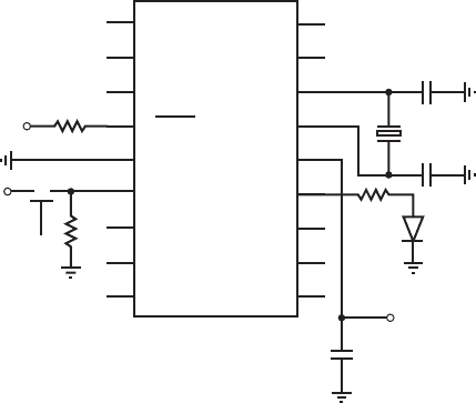
A simple example, called onint.bas, that illustrates the use of interrupts follows.
The corresponding schematic is shown in Figure 7.8 . The program’s function is
described in detail in the following paragraphs.
' onint.bas
' This program turns on an LED and waits for an interrupt on PORTB.0. When RB0
' changes state, the program turns the LED off for 0.5 seconds and then resumes
' normal execution.
led var PORTB.7 ' designate pin RB7 as "led"
OPTION_REG = $7F ' enable PORTB pull-ups and detect positive
' edges on interrupt
On Interrupt Goto myint ' define interrupt service routine location
INTCON = $90 ' enable interrupts on pin RB0
alc80237_ch07_258-345.indd 296alc80237_ch07_258-345.indd 296 12/01/11 12:52 PM12/01/11 12:52 PM

Confirming Pages
7.6 Using Interrupts 297
' Turn LED on and loop until there is an interrupt
loop: High led
Goto loop
' Interrupt handling routine
Disable ' disable interrupts until the Enable
' statement appears
myint: Low led ' turn LED off
Pause 500 ' wait 0.5 seconds
INTCON.1 = 0 ' clear interrupt flag
Resume ' return to main program
Enable ' allow interrupts again
End ' end of program
Figure 7.8 Interrupt example schematic.
PIC16F84
RA2
RA3
RA4
MCLR
V
ss
RB0
RB1
RB2
RB3
RA1
RA0
OSC1
OSC2
V
dd
RB7
RB6
RB5
RB4
1
2
3
4
5
6
7
8
9
10
11
12
13
14
15
16
17
18
5 V
22 pF
22 pF
4 MHz
1 k
1 k
5 V
0.1 μF
330
LED
5 V
NO
The onint.bas program turns on an LED connected to pin RB7 until an external
interrupt occurs. A normally open pushbutton switch connected to pin RB0 provides
the source for the interrupt signal. When the signal transitions from low to high, the
interrupt routine executes, causing the LED to turn off for half a second. Control
then returns to the main loop, causing the LED to turn back on again.
The first active line creates the variable name led to denote the pin identifier
PORTB.7. In the next line, the OPTION_REG is set to $7F (or %01111111) to
enable PORTB pull-ups and configure the interrupt to be triggered when the positive
edge of a signal occurs on pin RB0. The PicBasic Pro statement On Interrupt Goto
designates the label myint as the location to which program control jumps when an
interrupt occurs. The value of the INTCON register is set to $90 (or %10010000) to
properly enable RB0 interrupts.
The two lines starting with the label loop cause the program to loop continually,
maintaining program execution while waiting for an interrupt. The LED connected
alc80237_ch07_258-345.indd 297alc80237_ch07_258-345.indd 297 12/01/11 12:52 PM12/01/11 12:52 PM

Confirming Pages
298 CHAPTER 7 Microcontroller Programming and Interfacing
to pin RB7 remains on during this loop. The loop is called an infinite loop, because
it cycles as long as no interrupt occurs. Note that an active statement (such as High
led ) must exist between the label and the Goto of the loop for the interrupt to func-
tion, because PicBasic Pro checks for interrupts only after a statement is completed.
The final section of the program contains the interrupt service routine. Disable
must precede the label, and Enable must follow the Resume to prevent checking for
interrupts until control is returned to the main program. The interrupt service routine
executes when control of the program is directed to the beginning of this routine,
labeled by myint, when an interrupt occurs on pin RB0. At the identifier label myint,
the statement Low led clears pin RB7, turning off the LED. The Pause statement
causes a 500 millisecond delay, during which time the LED remains off. The next
line sets the INTCON.1 bit to 0 to clear the interrupt flag. The interrupt flag was set
internally to 1 when the interrupt signal was received on pin RB0, and this bit must
be reset to 0 before exiting the interrupt routine, so that subsequent interrupts can be
serviced. At the end of the myint routine, control returns to the main program loop
where the interrupt occurred. Lab Exercise 9 explores the concepts and example
presented in this section.
7.7 INTERFACING COMMON
PIC PERIPHERALS
This section introduces interfacing a PIC to two common peripheral devices. The
first is a 12-button keypad that can be used to input numeric data. The second is a
liquid crystal display that can be used to output messages and numeric information
to the user. More information on these and other useful peripheral devices can be
found online (see Internet Link 7.7).
7.7.1 Numeric Keypad
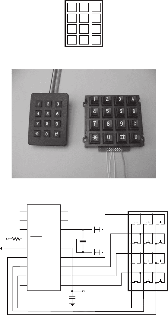
Figure 7.9 illustrates a common three-row, four-column 12-button keypad. Figure
7.10 shows a photographs of two common keypads. One has 12 keys with a ribbon
cable interface, and the other has 16 keys with solder holes to which individual wires
can be attached. Each key in a keypad is attached to a normally open pushbutton
switch. When a key is pressed, the switch closes. Figure 7.11 illustrates the electrical
schematic of the keypad with a recommended interface to the PIC16F84. A standard
keypad has a seven-pin header for connection to a ribbon cable socket. There is one
pin for each row and one pin for each column as numbered in Figure 7.11 .
The four rows (row 1, row 2, row 3, row 4) are connected to pins RB7 through
RB4, which are configured as inputs. Internal pull-up resistance is available as a
software option on these pins, so external pull-up resistors are not required (see
details in Section 7.8.1 ). The three columns (col 1, col 2, col 3) are connected to
pins RB0 through RB2, which are configured as outputs. The following PicBasic
Pro code contains initializations and a framework for a polling loop that can be used
to process input from the keypad. The column outputs are cleared low one at a time,
and each row input is polled to determine if the key switch in that column is closed.
Lab Exercise
Lab 9
Program-
ming a PIC
microcontroller—
part I
Internet Lin
k
7.7PIC I/O
interface devices
and useful
accessories
alc80237_ch07_258-345.indd 298alc80237_ch07_258-345.indd 298 12/01/11 12:52 PM12/01/11 12:52 PM

Confirming Pages
Figure 7.9 Numeric keypad .
1 2 3
4 5 6
7 8 9
*
0 #
Figure 7.10 Photograph of 12-key and 16-key numeric keypads.
Figure 7.11 Numeric keypad schematic and PIC interface.
PIC16F84
RA2
RA3
RA4
MCLR
V
ss
RB0
RB1
RB2
RB3
RA1
RA0
OSC1
OSC2
V
dd
RB7
RB6
RB5
RB4
1
2
3
4
5
6
7
8
9
10
11
12
13
14
15
16
17
18
5 V
22 pF
22 pF
4 MHz
1 k
5 V
0.1 μF
1
2
3
456
789
*
0#
1
2
3
4
567
col 1
col 2
col 3
row 1
row 2
row 3
row 4
keypad
7.7 Interfacing Common PIC Peripherals 299
alc80237_ch07_258-345.indd 299alc80237_ch07_258-345.indd 299 12/01/11 12:52 PM12/01/11 12:52 PM
Confirming Pages
300 CHAPTER 7 Microcontroller Programming and Interfacing
For example, if col 1 is low while col 2 and col 3 are high, and only the 1 key is
being held down, then row 1 will be low while the remaining row lines will be high,
indicating that only the 1 key is down. Statements could be added to the If statement
blocks, in place of the comments, to process the input.
' Pin assignments
row1 Var PORTB.7
row2 Var PORTB.6
row3 Var PORTB.5
row4 Var PORTB.4
col1 Var PORTB.2
col2 Var PORTB.1
col3 Var PORTB.0
' Enable PORTB pull-ups
OPTION_REG = $7f
' Initialize the I/O pins (RB7:RB4 and RB3 as inputs and RB2:RB0 as outputs)
TRISB = %11111000
' Keypad polling loop
loop:
' Check column 1
Low col1 : High col2 : High col3
If (row1 == 0) Then
' key 1 is down
Endif
If (row2 == 0) Then
' key 4 is down
Endif
If (row3 == 0) Then
' key 7 is down
Endif
If (row4 == 0) Then
' key * is down
Endif
' Check column 2
High col1 : Low col2 : High col3
If (row1 == 0) Then
' key 2 is down
Endif
If (row2 == 0) Then
' key 5 is down
Endif
If (row3 == 0) Then
' key 8 is down
Endif
If (row4 == 0) Then
' key 0 is down
Endif
alc80237_ch07_258-345.indd 300alc80237_ch07_258-345.indd 300 12/01/11 12:52 PM12/01/11 12:52 PM
