9-й Международный симпозиум по электромагнитной совместимости и электромагнитной экологии
Подождите немного. Документ загружается.

401
METHOD FOR ESTIMATING OF REALIZABLE PARAMETERS OF A
PREASSIGNED RADIATION PATTERN IN ANTENNA SYNTHESIS
PROBLEMS
D.
D.
G
ABRIELYAN
1
,
R
USSIA
,
E.
N.
M
ISHCHENKO
2
,
R
USSIA
,
S.
E.
M
ISHCHENKO
1
,
R
USSIA
,
I.
S.
S
AVCHENKO
1
,
R
USSIA
1
Rostov technological institute of service and tourism,
2
Rostov military institute of rocket troops, mihome@yandex.ru
The problem of assessing the realizable
requirements to antenna radiation pattern is one of the
key issues in the theory of synthesis of antennas. Applied
to antenna arrays of arbitrary geometry, the
corresponding analysis can be done only approximately.
The proposed method provides estimates for the
parameters of a preassigned radiation pattern, defined as
a function of these parameters leading to the smallest
deviation between the desired and the synthesized
radiation pattern. The method is based on the fact that a
solution to the synthesis of antennas on a preassigned
realizable radiation pattern is invariant to the choice of
method. This allowed us to use the analytical method of
amplitude-phase synthesis of antenna array for the
formation of the objective function, which depends on
the parameters of a preassigned radiation pattern, and
solve the optimization problem, using the known
gradient method.
Let us consider
N
-element antenna array radiation
pattern which is a superposition of radiation patterns of
radiators of antenna array:
( ) ( )
∑
=
ϕθ=ϕθ
N
n
nn
fwF
1
,,
, (1)
where
Nn ,...,2,1
=
;
n
w
is complex amplitude of excite
for
n
-th radiator;
(
)
uf
n
is complex function which de-
scribes radiation pattern of
n
-th radiator of antenna ar-
ray.
Suppose you want to solve the problem of synthesis
of the considered antenna array, which will result in, the
distribution of complex amplitudes of the excitation of
radiators
{
}
n
w
, providing minimal deflection pattern of
an antenna array
(
)
ϕθ,F
from a given pattern in the
sense of a given criterion:
{ }
(
)
(
)
(
)
ϕθϕθ ,,,min
0
FFQ
n
w
(2)
wher
(
)
(
)
(
)
ϕθϕθ ,,,
0
FFQ
is objective function synthesis.
Quality of design problems defined by choosing a
given pattern. If a given pattern can be realized by using
of the array is completely accurate, then the task of syn-
thesis corresponds to the objective function
(
)
(
)
(
)
0,,,
0
=ϕθϕθ FFQ
. The configuration of the an-
tenna array, a given functions
(
)
ϕθ,
n
f
, completely de-
termines the set of realizable beam patterns of antenna
array under consideration. If a given radiation pattern
represented as a function of parameters (in form, the
problem
arises of choosing the parameters
i
p
(
,...)2,1=i
of a given pattern
(
)
i
pF ,,
0
ϕθ
, which for the
considered antenna array provides the minimum possible
value of the objective function, ie, the problem of the
form:
{ } { }
( ) ( )( )
ϕθϕθ
i
wp
pFFQ
ni
,,,,minmin
0
. (3)
To solve the stated problem (3), we note that in the
case of realizable a given pattern of the objective
function goes to zero no matter what method is used to
determine the complex amplitudes of the excitation
coefficients
{
}
n
w
.
Therefore, to solve the problem of synthesis (2) use
the method of least squares, according to which we can
write:
( ) ( )
i
N
m
mmnin
pPpw
∑
=
η=
1
,
, (4)
where
1−
= SP
is inverse of the square matrix
(
Nm ,...,2,1
=
):
( ) ( )
∫ ∫
π π
π−
ϕθθϕθϕθ=
0
2/
2/
*
,
sin,, ddffS
mnnm
;; (5)
( ) ( ) ( )
∫ ∫
π π
π−
ϕθθϕθϕθ=η
0
2/
2/
*
0
sin,,, ddfpFp
miim
. (6)
Taking into account expressions (1) and (4)
formulation of the problem (3) can be rewritten as:
{ }
( ) ( ) ( )
ϕθηϕθ
∑ ∑
= =
i
N
n
i
N
m
mmnn
p
pFpPfQ
i
,,,,min
0
1 1
,
. (7)
Solution of (7), we find with the method of gradient
descent. For this we first define the initial values of the
iterative process:
0
i
p
and
0
λ
− given the parameters
of the radiation pattern and speed of approach to
extremum, respectively. After that, we find the
components of the gradient of the objective function.
In the numerical studies evaluated the optimal set of
parameters cosecans radiation pattern of arc antenna
array.
402
АСИМПТОТИЧЕСКОЕ РЕШЕНИЕ ВОЛНОВОГО УРАВНЕНИЯ
ДЛЯ ПОЛЯ ИЗЛУЧЕНИЯ ПРЯМОУГОЛЬНОГО РАСКРЫВА
С.
И.
С
ТАРЧЕНКО
,
Р
ОССИЯ
ФГУП Научно-исследовательский институт радио, e-mail: ssi@niir.ru
Аннотация. Предложено асимптотическое решение волнового уравнения для поля излучения,
создаваемого прямоугольным раскрывом, например, цилиндрическим зеркалом. Методом разложе-
ния по малому параметру получено уравнение для поперечной компоненты магнитного поля. Полу-
ченное решение может быть использовано в перспективных системах связи.
Abstract. Asymptotic solution of the wave equation is offered to derive a field radiated by a rectangular
aperture made, for example, of a cylindrical reflector. The small-parameter expansion technique is applied to
find out the equation for a transverse component of magnetic field. This solution may be used in calculations
concerning promising communication systems.
В настоящее время проблема создания
сходящегося канала электромагнитной энергии
является весьма актуальной в связи с возможностью
использования его в перспективных системах связи
[1]. В большинстве случаев эта задача решается
традиционным способом – созданием апертуры
больших электрических размеров, которая обеспечи-
вает формирование поля излучения в виде узкого
осе симметричного луча. Целью работы является
задача нахождения амплитудного распределения
поля в апертуре цилиндрического зеркала, которое
бы создавало уединенный канал электромагнитной
энергии с формой, близкой к пирамидальной и с
вершиной, лежащей в фокальной плоскости зеркала.
Постановка задачи
Пусть при z = 0 в плоскости XOY задан
плоский раскрыв прямоугольной формы больших
электрических размеров (а>>λ и b>> λ), как это
показано на рис. 1.
Рис. 1.
Такой раскрыв при его синфазном возбуждении
и определенном амплитудном распределении поля в
нем может создать в направлении оси OZ
уединенный канал энергии, если поле в раскрыве
удовлетворяет следующим условиям [2]:
Н
x
(x,y,z) = 0 при х = ± а/2 и y = ± b/2;
x
H (x,y,z)
0
z
∂
=
∂
при х = ± а/2.
Уединенный канал энергии имеет структуру
поля, повторяющую амплитудное распределение
поля в апертуре, причем по оси OZ амплитуды
составляющих поля до некоторого предельного
расстояния z
пред.
остаются постоянными. Физически
это означает, что обмен энергии через границы
канала при x =
±
a/2 и y =
±
b/2 отсутствует.
Решение задачи
Будем полагать, что в апертуре существует
только составляющая поля Н
x
(x,y,z), то есть
Н
y
(x,y,z) = 0, причем в любой точке полупространс-
тва при
0 z
≥
составляющая Н
x
(x,y,z) должна
удовлетворять однородному волновому уравнению:
2 2
x x
2 2
2
2
x
x
2
H (x,y,z) H (x,y,z)
x y
H (x,y,z)
k H (x,y,z) 0
z
∂ ∂
+ +
∂ ∂
∂
+ + =
∂
(1)
Будем искать решение этого уравнения в виде
произведения трех функций, каждая из которых
зависит от одной переменной:
x 1 2
H (x,y,z) F ( x) F ( y)
Ф(z)
= χ ⋅ χ ⋅
, (2)
где χ - параметр малости, равный χ = 1/ a.
Функцию Ф(z) будем искать в виде разложения
в ряд по степеням параметра малости χ. В этом
случае, в соответствии со свойствами степенного ря-
да, точность представления функции Ф(z) конечным
числом членов ряда будет определяться первым от-
брошенным членом ряда. Таким образом, функция
Ф(z) будет иметь вид:
403
2
0 1 2
3 4
3 4
Ф(z) Ф (z) Ф (z) Ф (z)
Ф (z) Ф (z) ...
= + χ + χ +
+ χ + χ +
. (3)
Тогда, с учетом выражения (3), выражение (2)
примет вид:
x 1 2 0 1
2 3 4
2 3 4
H (x,y,z) F ( x) F ( y)[
Ф (z) Ф (z)
Ф (z) Ф (z) Ф (z) ...] . (4)
= χ ⋅ χ + χ +
+ χ + χ + χ +
Найти искомые функции
1 2
F ( x), F ( y)
χ χ
и
Ф(z) можно, приравняв к нулю суммы при одинако-
вых степенях параметра малости χ.
Такой подход позволяет получить следующие
выражения для функций Ф
0
(z), Ф
1
(z), Ф
2
(z)… :
-jkz
0 0
Ф (z) A e
= ;
-jkz
1 1
Ф (z) A e
= ; (5)
2
jkz
2 0
(q q )
Ф (z) j A ze
2k
ν µ
−
+
=
; (6)
2
jkz
3 1
(q q )
Ф (z) j A ze
2k
ν µ
−
+
=
; (7)
2 2
jkz
4 0 0
2
q q
j
Ф (z) C A z 1 e
k
8k
ν µ
−
+
= + − −
, (8)
где
А
0
, А
1
, С
0
– амплитудные
коэффициенты;
q
ν
и q
µ
– коэффициенты распространения вдоль
осей ОХ и ОY, соответственно;
k = 2π/λ – волновое число свободного
пространства.
Подставляя выражения (5)…(8) в (3), можем
записать формулу для функции Ф(z):
2 2
jkz 2
0 1 0
2 2
3 jkz 4
1
2 2
0 0
2
q q
Ф(z) e A A j A z
2k
q q
j A z e
2k
q q
j
C A z 1 .
8k k
ν µ
−
ν µ
−
ν µ
+
= +χ + χ +
+
+ χ + χ ×
+
+ − −
После необходимых математических
преобразований можно получить решение волнового
уравнения (2) в следующем виде:
N M
jq y
jq x
1 1
2 2 2 2
2 3
0 1 0 1
2 2
jkz jkz 4
0 0
2
H(x,y,z) A e B e
q q q q
A A j A z j A z
2k 2k
q q
j
e e C A z 1 ;
k8k
µ
ν
± χ
± χ
ν µ
ν= µ=
ν µ ν µ
ν µ
− −
= ⋅ ×
+ +
× +χ + χ + χ ×
+
× + χ + − −
∑ ∑
где А
ν
, В
µ
– амплитудные коэффициенты.
Применение метода малого параметра к задаче
поиска решения волнового уравнения для поля
сходящегося потока энергии от цилиндрического
зеркала позволяет получить это решение в первом
приближении с достаточной для практики
точностью. Полученное решение подтверждает
возможность создания уединенного сходящегося
канала электромагнитной энергии пирамидальной
формы, что, в свою очередь, может послужить
основой технических решений при создании
современных систем связи.
Литература
1. Проблемы антенной техники. Под ред. Л.Д.
Бахраха и Д.И. Воскресенского. -М.: Радио и связь,
1989.
2. Терешин О.Н., Седов В.М., Чаплин А.Ф.
Синтез антенн на замедляющих структурах. - М.:
Связь, 1980.
404
COMPENSATION OF FIELDS IN NEAR ZONE
M.
H
ARIDIM
,
I
SRAEL
,
B.L
EVIN
,
I
SRAEL
,
M.
B
ANK
,
I
SRAEL
Holon Institute of Technology, e-mail: levinpaker@gmail.com
Abstract. The results of developing the compensation method described in the report at the preceding
conference are presented. The shape and dimensions of the dark spots and the irradiation reduction factor in
the spots are determined. Methods for placement of the radiators ensuring minimal distortions of the pattern
in the horizontal plane are determined. The use of array instead of one additional radiator can effectively
increase the dark spot dimensions. It is shown that as in the case of two monopoles with equal lengths the
structure of two monopoles with different lengths can be modeled as a combination of two-wire transmission
line and monopole with stepped change of equivalent radius.
Introduction
In the use of personal cellular phones, during a
conversation the hand-set unit is placed next to the user’s
head, and sensitive parts of user’s body (brain, eyes, etc.)
are exposed to EM irradiation. It is necessary to reduce
the amount of the EM energy, absorbed in the head.
Protection against the EM field by screening or
absorbing seems to be obvious, but in practice this idea
is not applicable.
The protective action of the proposed compensation
method [1, 2] is based on a different principle: mutual
suppression of fields created by various radiating
elements in a certain area. In accordance with this
method, in addition to the main radiator (1 in Fig. 1) a
second (additional) radiator (2 in Fug. 1) is located in the
plane passing through the compensation point and the
feed point of the main radiator, as shown in Fig. 1.
The second radiator is placed between the head and
the main radiator and is exited approximately in anti-
phase to it (not exactly anti-phase because of the field’s
phase progression along the interval between the
radiators). Then the radiators’ fields will compensate
each other in some point inside the head, and around this
point a zone of a weak field (a dark spot) will arise.
This paper is devoted to the results of the
compensation method development.
The irradiation reduction factor
The geometry of the problem is shown in Fig. 2. As
it was shown in [2], the mutual coupling between closely
located asymmetrical radiators (monopoles) affects the
current distribution along each radiator, such that they
will include anti-phased components besides the in-
phase components. For equal radius wires, the in-phase
and the anti-phased currents of the first radiator are
Fig. 1. The compensation method
( )
(
)
kL
zLk
YeezJ
iA
sin
sin
)(
2211
−
+=
,
( )
(
)
kL
zLk
YeezJ
aA
sin
sin
)(
1211
−
−=
. (1)
Here
z
is coordinate along each radiator axis,
L
is the
length of radiators,
k
is the propagation constant,
1
e
and
2
e
are emf’s (electromotive forces) in the bases of the
first and second radiators,
(
)
RkLjWY
l
2cot1
1
+−=
and
(
)
[
]
RaLZY
em
2,41
2
+=
are accordingly the input
admittances of the two-wire line and the monopole, into
which the initial circuit is divided. At that
l
W
is the
wave impedance of the line,
(
)
em
aLZ ,
1
is the input
impedance of monopole with length L and equivalent
radius
e
a
=
ab
,
R is
the generator impedance.
The total field of the first radiator in plane
0
=
ϕ
is
given by
(
)
(
)
[
]
12122111
30)( YeeYeeFjzE
rz
−++−=
ε
, (2)
where
( )
[
+
−=
11
exp
sin
1
mmm
RjkR
kL
F
(
)
−
−
22
exp
mm
RjkR
(
)
]
.expcos2
0 mom
RjkRkL −−
Here
( )
2
2
1 mm
LzR
ρ
+−=
,
( )
2
2
2 mm
LzR
ρ
++=
,
22
0 mm
zR
ρ
+=
. The total field of
the second radiator in plane
0
=
ϕ
is
(
)
(
)
[
]
11222122
30)( YeeYeeFjzE
rz
−
+
+
−
=
ε
. (3)
In order to nullify the total field in the compensation
point (
0,0,
0
ρ
), i.e.
(
)
0)0()0(0
21
=
+
=
zzz
EEE
, the
Fig. 2. Radiators’ placement next head
405
ratio of the radiators feeding emf’s must be equal to
(
)
( )
20211012
20121012
1
2
)(
)(
FYYFYY
FYYFYY
e
e
++−
−
+
+
−=
. (4)
Here
0m
F
is the value of the function
m
F
in the
compensation point. Equation (4) allows finding the
voltage amplitude and phase at the input of the second
radiator, if the amplitude and phase at the input of the
first radiator are known.
Using expressions, derived in [2]:
( )
12
2
1
21
2
2
YY
e
e
YY
e
J
A
−++=
,
( )
12
1
2
21
1
1
YY
e
e
YY
e
J
A
−++=
,
we can find the driving currents ratio for given values of
the geometrical dimensions b and ρ
0
,
201012
FFJJ
AA
−
=
. (5)
Here, the required current ratio coincides with its value
in the absence of mutual coupling between the radiators.
That occurs when the radiators are of the same length.
At
4
λ
=
L
, we obtain, in the first-order approximation:
(
)
,exp
101010
RjkRF −=
(
)
202020
exp RjkRF −=
,
i.e.
(
)
[
]
,exp
11022011022012
RRRjkRJJ
AA
−
−
−
=
(6)
where
( )
2
0
2
110
2
0
2
220
, bLRLR ++=+=
ρρ
.
As it follows from the above expressions, the dipole
moments of linear radiators must be in inverse
proportion to the distances from the radiators to the
compensation point.
The dark spot dimensions for dipoles of finite
length can be calculated using equations similar to (2)-
(3) written for the field of such radiators in cylindrical
coordinates. The dark spot boundary is determined by
radius
n
ρ
, at which
10zz
EEn =
is equal to a given
value, e.g.,
1.0
=
n
, where
z
E
is the total field and
10z
E
is the field of the main radiator. Let us assume, for
the sake of simplicity, that the electric field strength
increases linearly from the compensation point
0
=
t
to
the dark spot boundary
0
tt
=
such that
nsEE
zz
=
10
,
where
0
tts
=
,
)(sconstn
=
, and hence the losses
power exhibits a quadratic growth with the distance. The
total losses power inside the spot is given by
3/)(
2
0
1
0
2
0
nPdsnsPP
∫
==
, where
0
P
is the losses power
due to the main radiator in the absence of the auxiliary
radiator, within the limits of spot. For
n
0
=0.2 the losses
power is diminished by a factor of 3/ (0.2)
2
=75 (or 18.8
dB). For
0
n
=0.1 the reduction factor is 300 (24.8 dB),
and for
0
n
=0.04 the factor is 1875 (32.7 dB). Actually
this factor roughly is half as many.
The shape and dimensions of the dark spots
To find the boundary surface of the dark spot, one
must determine the value of
n
ρ
as a function of z and φ.
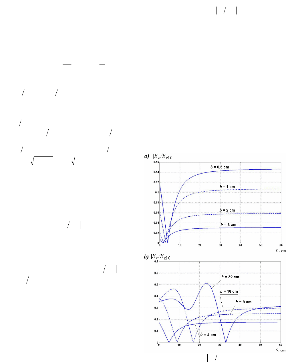
In Fig. 3 the field ratio
10
zz
EEn =
is plotted as a
function of
ρ
assuming
1,5.7,30
0
===
ρλ
L
for
different values of b (all dimensions are in centimeters).
The field values
10z
E
and
z
E
are calculated at
0,0
=
=
ϕ
z
by the above formulas.
The boundaries of the dark spot in the
ρ
direction,
noted as points
1
ρ
and
2
ρ
, are found as the intersection
points of curve n with a given level
0
n
. Along the
1
ρ
2
ρ
segment, n is smaller than the required value
0
n
.
The length
1
ρρρ
−=∆
2
of this segment, i.e. the dark spot
length, is presented in Table 1 for different values of b
and
0
n
(all dimensions are in centimeters), i.e. for
different levels of field decrease at the dark spot
boundary. From Table one can see that the dark spot
length increases somewhat when the distance b between
radiators grows, but at that the level of field increases at
the dark spot boundary also, and
ρ
∆
at the same level
0
n
Fig. 3. Variation of
10zz
EEn =
along the
ρ
axis
406
Table I. The dark spot length for different b and
0
n
b n
0
=0.01 0.02 0.04 0.07
0.5 3.53 6.80
1 1.89 3.89 7.67
2 1.00 2.00 4.17 8.12
3 0.71 1.42 2.91 5.43
b n
0
=0.07 0.10 0.14 0.25
4 4.28 6.58 11.38
8 2.89 4.29 6.43 49.60
16 2.44 3.56 5.24 23.63
32 2.29 3.35 4.88 11.73
decreases. Therefore at small values of b the curve n has
narrower and downward excursion is deeper.
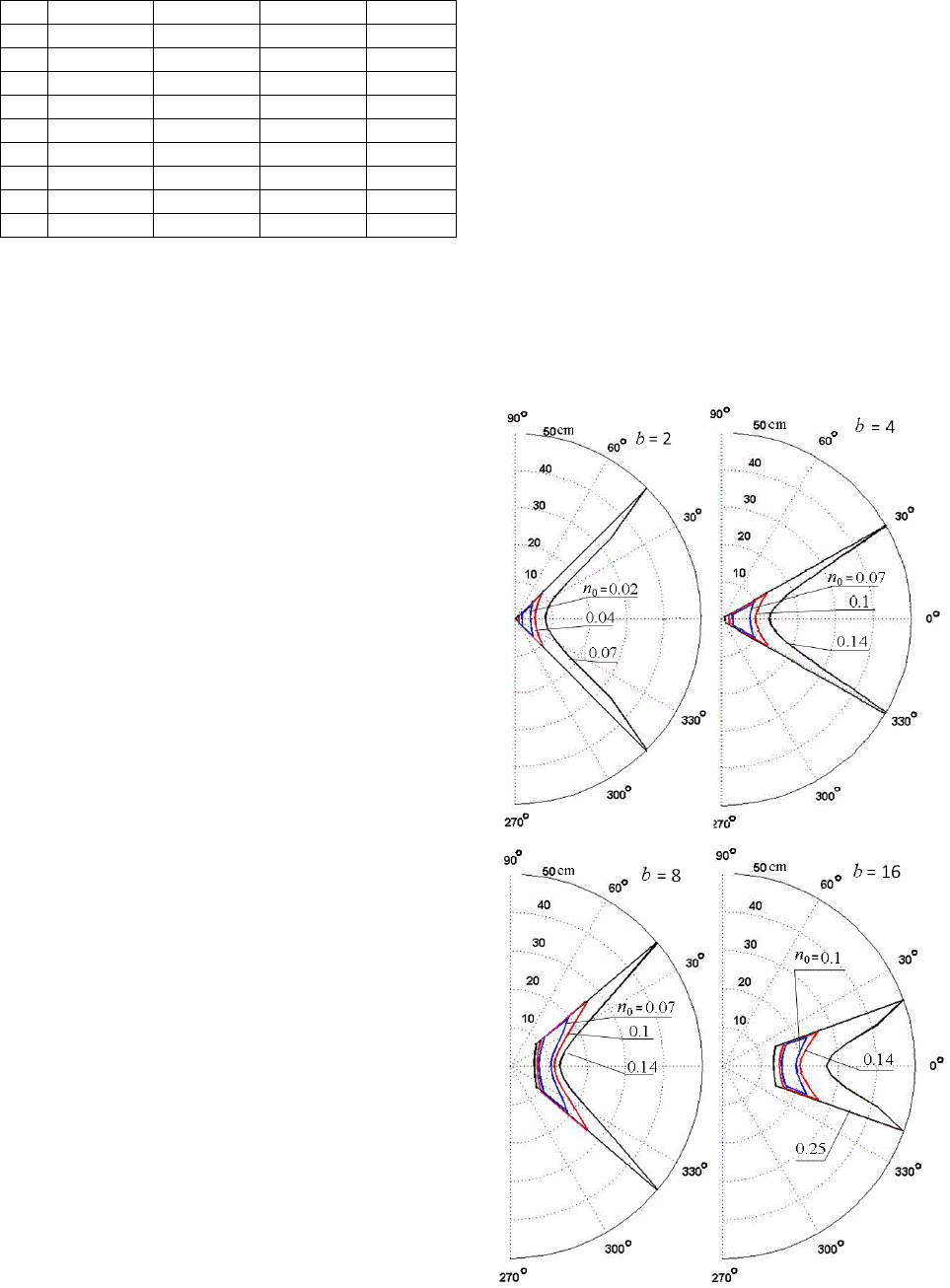
Fig. 4 shows a few examples of the dark spot
boundaries in the horizontal plane (
0
=
z
) for the
frequency f=1 GHz,
1
0
=
ρ
cm and different values of b
and
0
n
. In this figure the fields
10z
E
and
z
E
are
calculated using equations (3) at
0
=
z
and the given
angles
ϕ
, similarly with preceding case. Coordinates
1
ρ
and
2
ρ
of the start and end of the corresponding straight
line segment with
0
nn ≤
are fixed.
One can use this method in order to plot the dark
spot boundaries also in the vertical plane.
Fig. 4 and Table 1 show that at cellular frequencies
in the range of gigahertzes, it is sufficient to separate the
radiators by a small distance of the order of a few
centimeters. Since the auxiliary radiator’s power is
significantly smaller than that of the main antenna, in the
far region the field of the main radiator predominates,
i.e. the total field is only slightly different from that of
the main radiator.
It is seen from Fig. 4 that the dark spot width as a
rule is greater than its length. The spot height is close to
its length. This result is particularly important as it
shows in which direction the head movements are more
critical in terms of the absorbed power increase.
The calculations also show that upon optimal design
of the structure, in terms of the relative positions of the
radiators and the compensation point, the volume of the
dark spot increases, and the field inside this spot
substantially decreases. One can choose the structure
parameters so that the spot dimensions coincide with the
human head dimensions, resulting in a big reduction of
power losses in the head. Employing a multitude of
auxiliary radiators allows in principle a further increase
of the dark spot volume.
The antenna structure pattern
The use of an additional radiator in the
compensation method involves a contradictory relation
between the requirements of field reduction in the near
region and of preservation of the circular pattern in the
horizontal plane. Preservation of the far field strength
and pattern is a crucial issue for any method of SAR
(Specific Absorption Rate) reduction. In order to
preserve the circular form of the pattern, and in
particular to avoid a deep gap along the structure axis,
the phases of the far fields created by the radiators
should not differ by more than a few degrees. Closeness
of antennas and their currents phases ensure circular
form of structure pattern. On the other hand, in order to
nullify the total field at the compensation point, the
radiators' fields at this point must be in anti-phase.
If the driving current of the main radiator is
1A
J
, the
driving current of the auxiliary radiator is
ψ
j
AA
DeJJ
−
=
12
, where D is the ratio of the radiators’
dipole moments, and ψ is the phase difference between
these driving currents. In this case, the field
of the
auxiliary radiator is
ju
DeEE
12
=
, where E
1
is the field
of the main radiator, and
ψ
−
=
klu
. Here l is the path
407
Fig. 4. Dark spot boundaries in the horizontal plane
difference between rays from the radiators to a point
located at angle
ϕ
(see Fig. 2). Since the total field of
both radiators equals
21
EEE +=
, one can write for
the pattern in the horizontal plane
( )
mm
ju
uDuD
De
F
22
2
sincos1
1
++
+
=
. (7)
Here
m
u
is the value of
u
at the denominator maximum.
Since D and
m
u
are constant, the denominator of (7)
doesn’t depend on
ϕ
, and hence the ratio between the
pattern maximum and minimum, an indicative of the
pattern distortion level, is equal to
D
D
De
De
F
F
ju
ju
m1
1
1
1
min
max
min
max
±
=
+
+
=
, (8)
where the upper sign applies when D is positive, and the
lower sign applies if D is negative. It is easy to show that
when the pattern maximum and minimum differ by 6 dB
(deviation of 3 dB from the average level), we
obtain
33.0=D
, and when the difference between
maximum and minimum is 3 dB, we have
17.0=D
.
Since from Fig. 2,
bR
+
=
01
ρ
,
02
ρ
=R
, then,
using (5), we have
(
)
bRRD
+
=
=
0012
ρ
ρ
, which
reduces to a
02
2
0
2
0
=−− bb
ραρ
, where
.11
2
−= D
α
The solution of this quadratic equation is
β
ρ
b
=
0
,
where
.11 −= D
β
Let's consider the case when the
main radiator is located on the structure axis, at the
distance 3 cm from the head, i.e.,
3
0
=+b
ρ
, and the
compensation point is placed on the head surface. In this
case if
33.0
=
D
, then
2
=
β
,
2
0
b=
ρ
=1,
2
=
b
.
If
D
is equal to 0.17, then
88.4
=
β
,
5.0
0
=
ρ
,
5.2
=
b
.
There results show that applying the compensation
method together with essential decrease of irradiation
may give predictable change of the pattern, which
requires for increase of corresponding power along the
structure axis. But this change is small and controls by
selection of distances between radiators.
Two monopoles with different lengths
The two radiators system is divided into two
circuits. If the wires have equal lengths, the line length
and the monopole height equal the wire length. But, if
the wires have different lengths, it is necessary to
determine the input impedance of each circuit and the
current distribution along each wire [3].
A two-wire line consisting of parallel wires of
unequal lengths has two sections: a lower section of
length
2
lL =
and an upper section of length
21
lll −=
,
where
1
l
is the length of the longer radiator, and
2
l
is
the length of the shorter one. The lower section consists
of two parallel wires of circular cross section of the same
lengths and radii. We shall take account of the upper
section effect on the line input impedance by calculating
the capacitance between the upper part of the longer wire
(of length
l
)
and the short radiator. This capacitance
equals the difference of two capacitances:
LCCC
01
−=
. (9)
Here
1
C
is the total capacitance between the longer and
the short wires (see, for example [4]),
0
C
is capacity per
unit length between wires of the line.
The current distribution along the monopole wires
is calculated in accordance with the theory of electrically
coupled lines located under ground, developed by A.
Pistolkors [5]. In this case, since the line wires have
different lengths, it is necessary to divide the equivalent
line to two sections. The obtained expressions show that
the current along both sections of the monopole is
distributed in accordance with sinusoidal law as in the
known case of a monopole consisting of two segments
each with different wave impedances (for example, with
different wire diameters).
One can see from calculation results that in a first
order approximation, the length of the equivalent line’s
wires is quite close to that of the shorter wire, and the
monopole length is equal to the length of the longer wire.
The obtained theoretical results were verified by the
CST simulation. The calculation and simulation results
are close to each other and show that the input
impedance of a line with different wire lengths differs
somewhat from the input impedance of a line with wires
having the same lengths as the shorter wires, and the
impedance of the monopole with different wire lengths is
near to the impedance of the monopole with the long
wires.
References
1. M. Bank and B. Levin, “The development of the
cellular phone antenna with a small radiation of human
organism tissues”,
IEEE Antennas Propagat. Magazine
,
vol. 49, pp. 65-73, Aug. 2007.
2. M. Bank
,
M. Haridim
,
B. Levin,
“
Linear
radiators in near zone,” in Proc. of the 8
th
Intern. Symp.
on Electromagn. Comp. and Electromagn. Ecology, St.
Petersburg, June 2009, pp. 90-93.
3. M. Haridim
,
B. Levin, M. Bank
, etc., “
Mutual
coupling of near collocated monopoles,” in Proc. of
10
th
WSEAS Intern. Conf. on Electr., Hardware,
Wireless and Opt. Comm., Cambridge, Febr. 2011, pp.
314-317.
4. U. J. Iossel, E. S. Kochanov, and M.G. Strunsky,
Calculation of Electrical Capacity, St.-Petersburg:
Energoisdat, 1981.
5. A. Pistolkors,
Antennas,
Moscow: Sviyazizdat,
1947.
408
TRANSPARENT ANTENNAS
B.
L
EVIN
,
I
SRAEL
,
M.
H
ARIDIM
,
I
SRAEL
Holon Institute of Technology, e-mail levinpaker@gmail.com
Abstract. The calculation method of the transparent metal materials’ parameters is refined. The equation
for the current along the transparent metal radiator is written and solved. On the base of the equation
solution the currents distribution along the radiator axis was analyzed. It is shown that transparent materials
depending on their parameters are fallen into two different groups, which permit to produce two different
types of the currents distribution. Calculations and simulation results for different transparent antennas are
presented. The concrete variant of the antenna is offered.
Introduction
Transparent materials fabricated as ITO-coating on
high-quality glass substrates are electrically conductive
and optically transparent and have high sheet resistance
homogeneity that permit to apply them in the capacity of
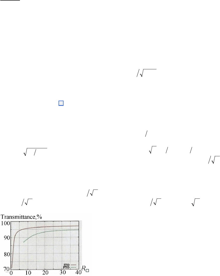
flat antennas for mobile communication. In Fig. 1, which
is quoted from [1], for example the dependence of the
film transmittance (in per cents) on its sheet resistivity
R□ (in Ohms to square area) for the light wavelength 550
nm is given. From the Figure one can see that the
transmittance increases with the resistivity grows, and
sufficiently high transmittance (near 95%) is ensured, if the
film resistivity is greater than 5 Ω/ . At that transparent
conductive film ITO (Indium-Tin-Oxygen), which
consists ofIn
2
O
3
, ZnO and SnO
2
, has higher transmittance
than film FTO (Fluorine-Tin-Oxygen).
In accordance with Leontovich impedance
boundary condition, if the thickness of the film is greater
than the penetration, the loss resistance of a metal surface
square section, Ohm, equals (see, for example, [2]):
R□
(
)
σλµ
r
41.34=
, (1)
where
r
µ
is the relative permeability of a metal, σ is its
specific conductivity for the constant current, Cm/m, λ is
the wave length, m. Copper and aluminum often are used
as metals in making antennas, their specific conductivity
equals accordingly 5.8·10
7
and 3.5·10
7
Cm/m, i.e. the loss
resistance of a square section equals
λ
3
1052.4
−
⋅
and
λ
3
1092.5
−
⋅
. The conductivity of the materials
Fig. 1. Example of the film transmittance dependence on
its sheet resistivity R□
ITO used in the transparent antennas is lower
substantially. For example, the sheet resistivity of the
film CEC005P equals approximately 4.5 Ohm. The sheet
resistivity is the resistance of a square section with the
thickness, equal to penetration. The penetration
δ
is
calculated in accordance with the expression
µσπδ
f1=
. (2)
At that usually
7
0
104
−
⋅==
πµµ
, since
1
=
r
µ
. One
can calculate the specific conductivity σ with the help of
expression (1), if the magnitude R□ is known:
=
σ
34.41
2
/( λ R□
2
). (3)
The frequency f in (2) and further is given in GHz.
If the thickness d of the film is smaller than the
penetration
δ
, the loss resistance of a metal surface
square section equals
0
R
= R
□
d
δ
. (4)
From expressions (2)-(4) we find:
σ=649.7f,
f/1025.6
4−
⋅=
δ
,
fd 2016
=
δ
(it was taken
into account that d=0.31
.
10
-6
m),
fR 9072
0
=
. At
the frequency 1 GHz (λ =0.3 m) the resistance
0
R
equals 9072 Ohm.
The comparison of
0
R
for the transparent film with
the losses resistance in the copper
0
R
=
=R
□
=
f
33
1025.81052.4
−−
⋅=⋅
λ
shows as the
difference between losses in the copper coat and in thin
transparent film is great.
Current distribution along radiators
Knowledge of antenna current structure, in
particular knowledge of current distribution law along
the radiator axis, is of great importance for
understanding of physical processes in the antenna. Let
us write equation for the current in the flat antenna in
accordance with the integral equation for the current in
the thin cylindrical antenna with nonzero (impedance)
boundary conditions at its surface (see, for example, [3],
chapter 3).
In Fig. 2 the known variants of asymmetrical flat
radiators, which are set at the ground having the form of
409
infinite metal sheet, are presented: a) the narrow
rectangular plate, b) the wide rectangular plate, c) the
self-complementary flat antenna. These variants are
chosen, in order to compare theirs with each other and
with the thin cylindrical monopole with the circular cross
section of the radius а (variant d). Components, which
don't influence on electrical characteristics, but may
become necessary for construction durability, are shown
in Fig. 2c by the dotted line. If the monopole
characteristics are known, then with the help of them the
characteristics of the dipole (of the symmetrical radiator,
the dimensions of which every arm coincide with the
monopole dimensions) are calculated easily.
The equation for the current J(z) in the thin
cylindrical antenna in the first with respect to
χ
approximation has the form
(
)
( )
( ) ( )
zKjzJUk
dz
zJd
0
2
2
2
4
ωεπ
−=−+
, (5)
and
aZjU
χωε
0
2=
. Here z is the coordinate along
the antenna axis,
λ
π
2
=
k
is the wave propagation
constant along the perfectly conducting metal surface,
(
)
(
)
zezK
δ
=
is extraneous electromotive force,
χ
is
the small parameter of the thin antennas theory
(
Ω
=
1
χ
, where Ω is the parameter used by Hallen),
ω
is the circular frequency,
Z
is the surface impedance
of antenna, which in this case equals
0
R
.
Let us pass from the cylindrical antenna to the flat
one. The small parameter
χ
is related with the linear
capacity magnitude
1
C
(capacity per unit length) of the
dipole by the relationship
(
)
χπεπε
001
22ln == aLC
.
Therefore we replace
χε
0
with
π
2/
1
C
. And the linear
capacity
1
C
of the flat dipole equals
(
)
( )
nKnKC
2
01
1−=
ε
. Here
(
)
nK
is the total
elliptical integral of the first kind of argument n (see, for
example, [4], Section 6). The magnitude n depends on
the plates form:
(
)
2sin1
φ
−
=
n
, where
φ
is the
Fig. 2. The variants of asymmetrical flat antennas:
a) the narrow rectangular plate, b) the wide
rectangular plate, c) the self-complementary flat
antenna, d) the thin monopole of the circular
section
triangle vertex angle in the point of the plate connection
to the generator. In the case of self-complementary
antenna this angle is equal to 90°, and the magnitude n
equals
(
)
146.02707.01
=
−
=
n
. Let us find the
values
(
)
nK
and
(
)
2
1 nK −
in tables (see, for
example, [5], Section 9):
(
)
,5793.1
=
nK
(
)
3233
.31
2
=−nK
, i.e.
11
1
1086.1
−
⋅=C
F. In the
case of rectangular plates
φ
=0, n=0.5,
(
)
6858.1
=
nK
,
(
)
1565.21
2
=−nK
, i.e.
11
1
1013.1
−
⋅=C
F.
Let us replace the cross section perimeter
a
π
2
of
cylindrical antenna with the cross section perimeter of
the flat antenna: it equals 2b for the rectangular plate and
z
4
for the self-complementary antenna. Let us write the
imaginary one as
(
)
2
1707.0 +−=− jj
. In the issue we
obtain
2
1
22
kkUk +=−
, (6)
where
α
α
jk
±
−
=
1
, and
bRC
01
707.0
ωα
=
for
the rectangular plate and
(
)
zRC 2707.0
01
ωα
=
for
the self-complementary antenna. In order to use the
common solution of the equation for the current, the
magnitude
α
must be constant from
z
. Let us divide for
that the radiator arm to short segments and write an
individual equation for the each segment considering
that the magnitude 2
z
, where
z
is the coordinate of the
segment center, and it is constant at the each segment.
Further one can calculate currents in the all segments
and join them at the segments’ boundaries.
Transparent radiators with the high and small
surface resistivity
Let us consider different variants of ratios
2
k
and
2
1
k
. If the magnitude
2
1
k
is substantially greater
than
2
k
, then, neglecting by the term
2
k
, let us write the
equation for the current in the each segment in the first
with respect to
χ
approximation:
(
)
( ) ( )
zKjzJk
dz
zJd
0
2
1
2
2
4
ωεπ
−=+
. (7)
The equation solution has the shape:
(
)
(
)
(
)
(
)
lzLzJzJ
ααα
sinsinexp0 −−=
. From
that it is seen that the current distribution along antenna
has the form of the exponential curve diminished from the
generator to the antenna free end. The greater
α
is the
sharper curve is and the smaller effective length and
efficiency of radiator are. The magnitude
α
as it was
shown earlier depends on the form and the width of the
plate. But, if the film conductivity is small, then at the any
plate form and width the antenna radiation resistance and
efficiency are small and the level of its matching with the
signal source is low, i.e. the radiation power is small.
410
It is seen from presented earlier expression for
α
that its magnitude is greater in the case of the self-
complementary antenna than in the case of the
rectangular plate especially near the feed point where the
self-complementary antenna width is vanishingly small.
The small effective length and very small radiation
resistance are consequence of the quick attenuation of
the current along antenna. And so at the great surface
resistivity of the film the antenna of the rectangular
plates has unconditional advantage in comparison with
the self-complementary one.
If the surface resistivity is small so that the
magnitude
2
1
k
is substantially smaller as
2
k
then the
equation for the current in the first with respect to
χ
approximation will have the form:
(
)
( ) ( )
zKjzJk
dz
zJd
0
2
2
2
4
ωεπ
−=+
. (8)
In this case the current distribution along the
radiator has in the first approximation the sinusoidal
character:
(
)
(
)
(
)
,sinsin0 kLzLkJzJ −=
i.e. the
losses power in the rectangular flat dipole of width b
equals
(
)
( )
dzzLk
kLb
RJ
P
L
−=
∫
0
2
2
0
2
sin
sin
0
. Since
( )
−=−
∫
kL
kLL
dzzLk
L
2
2sin
1
2
sin
0
2
, then loss resistance is
( )
−==
kL
kL
kLb
LR
J
P
R
loss
2
2sin
1
sin20
2
0
2
. (9)
If
4
λ
=
L
, then
2
π
=
kL
,
b
LR
R
loss
2
0
=
. At
bL 10
=
0
5RR
loss
=
, at
bL
=
0
5.0 RR
loss
=
.
In the case of the self-complementary dipole its
width depends on coordinate z namely
zb 2
=
.
Thereafter
( )
z
dz
zLk
kL
R
R
L
loss
−=
∫
∆
2
2
0
sin
sin2
, where
∆
is
a small magnitude, i.e.
( )
[
]
( )
10.)22(2sin)2
2(2cosln
sin4
2
0
∆−+∆−
−−∆⋅=
kSikLSikLkCi
kLCikLL
kL
R
R
loss
Functions
Cix
and
Six
are integral cosine and sine.
Since
∆
is small, then
∆
−
≈
∆
kCkCi 2ln2
(C=0.5772… is Euler’s constant),
∆
≈
∆
kSi2
. At
2
π
=
kL
we obtain
π
CikCJ
−
∆
−
=
2ln
1
. Hence
(
)
[
]
=
+
∆
+
−
∆
=
π
CikCLRR
loss
2lnln25.0
0
(
)
4/ln
0
π
π
CiCR
+
−
=
. Since
145.1ln
=
π
, and
084.0
=
π
Ci
(see, for example, [5], Section 6), then
0
164.0 RR
loss
=
.
Comparison of derived results shows that at the
small surface resistivity the self-complementary antenna
is better than the rectangular one in the view of losses in
its metal surface. For example, the losses in it are
considerably smaller than in the plate with the constant
width b, equal to
10L
. Even if b=L (if b equal to mean
width of the self-complementary antenna), then in this
case the losses in the antenna with the constant width
three times as many.
In order to define more precisely this conclusion, it
is expediently to show what means the great surface
resistivity and the small one. In the first case the
magnitude
2
1
k
is substantially greater as
2
k
and in the
second case the opposite relationship occurs. In order to
k
will exceed
1
k
four-five times as many, it is necessary,
as follows from (6), to decrease
0
R
300-400 times at the
expense of increasing the material conductivity and the
transparent film thickness. At present time this result is
unlikely.
Calculations and simulation of antennas variants
Let us start with the analysis of the flat symmetrical
radiator (dipole) fabricated from two rectangular plates
with length and width 7.5 cm (Fig. 2b). The arm length
of the radiator is equal to the quarter of a wave length at
the frequency 1 GHz.
At this frequency the value
α
in that case equals
65.5, i.e.
6.92
1
=k
,
3.20=k
, and
6.19/
2
1
=kk
.
Considering that the current along its arm is distributed
according to the law
(
)
(
)
(
)
zJzJ
α
−
=
exp0
, we shall
calculate the effective height of the radiator. The area
under the current curve equals
( ) ( ) ( ) ( )
[ ]
( )
lJlJdzzJS
l
0/exp10exp0
0
≈−−=−=
∫
ααα
.
As the upper limit l of integral we take the coordinate of
the point, in which the current is decreased by e times,
i.e.
2
1053.1/1
−
⋅==
α
l
. The radiator effective height
equals
2
1005.32
−
⋅==
α
e
h
, the radiation resistance
is
(
)
1.820
2
==
Σ e
khR
Ohm. The loss resistance in the
flat rectangular radiator is equal to the power in the
antenna divided to the square of the generator current:
( ) ( )
1845
202
0
0
0
22
=≈=
∫
blRdzbRzJJR
l
loss
, and
consequently,
(
)
3
104.4
−
ΣΣ
⋅=+=
lossrad
RRR
η
.
The current along the flat self-complementary
antenna arm (Fig. 2с) is distributed according to the
law
(
)
(
)
(
)
zaJzJ −= exp0
. Using substitution