9-й Международный симпозиум по электромагнитной совместимости и электромагнитной экологии
Подождите немного. Документ загружается.

301
0,5 0,75 1 1,25 1,5
x
=
ω
/(
ω
N
k
)
С
п
е
к
т
р
а
л
ь
н
а
я
п
л
о
т
н
о
с
т
ь
1
2
Рис. 2. Структура спектра 16-и импульсов:
1 – четыре пачки по четыре импульса при g
M
=4;
2 – 16 импульсов в одной пачке.
Некоторые примеры модификации спектра
Рассмотрим некоторые практические примеры
модификации структуры спектра при изменении
пачечной структуры последовательности импульсов
с фиксированной частотой
ω
N
их следования и
фиксированной полной длительностью
последовательности. Последнее означает, что
ширина линий полосатого спектра во всех случаях
одинакова.
1. Пусть полное число импульсов в
последовательности пачек фиксировано
(NM = const). Определим различие спектров
последовательностей с «длинными» и с «короткими»
пачками при фиксированной скважности g
M
их
следования (рис. 3).
0,5 0,75 1 1,25 1,5
x
=
ω
/
(
ω
N
k
)
С
п
е
к
т
р
а
л
ь
н
а
я
п
л
о
т
н
о
с
т
ь
1
2
Рис. 3. Структура спектрального распределения
пачечной последовательности импульсов фиксиро-
ванной длительности при g
M
= 2: 1 – «короткая»
пачка: четыре пачки по два импульса; 2 – «длинная»
пачка: две пачки по 4 импульса.
При равном числе импульсов равны
интенсивности центральных спектральных линий.
При равной длительности последовательностей
ширина их спектральных линий (полос) одинакова.
Чем короче пачка, тем больше частота
следования пачек (
ω
M
~
1/N) и больше частотный
интервал, разделяющий линии полосатого спектра.
Спектр «короткой» пачки относительно более
широкий (∆
ω
N
~
1/N), поэтому линии полосатого
спектра в окрестности центральной линии спектра
разнесены на больший интервал.
Таким образом, при фиксированной
длительности последовательности пачек и
фиксированной скважности g
M
их следования, чем
длительность пачки меньше, тем больше степень
уширения спектральной области в окрестности
центральной спектральной линии.
2. Определим различие спектров
последовательностей с «длинными» и c «короткими»
пачками, но теперь при фиксированной частоте
ω
M
их следования (рис. 4).
При фиксированной частоте
ω
M
линии
полосатого спектра размещены с равными
интервалами. Причем ширина линий одинакова,
поскольку она определяется только полной
длительностью последовательности.
Изменение длины пачек при заданных условиях
ведет к изменению полного числа импульсов (NM) в
последовательности. При этом изменяется энергия
последовательности (~NM) и амплитуда
центральных линий спектра ~(NM)
2
.
0,5 0,75 1 1,25 1,5
x
=
ω
/
(
ω
N
k
)
С
п
е
к
т
р
а
л
ь
н
а
я
п
л
о
т
н
о
с
т
ь
1
2
Рис. 4. Структура спектрального распределения
пачечной последовательности импульсов фиксиро-
ванной длительности при
ω
M
= const: 1 – «длинная»
пачка: 2 пачки по 4 импульса при g
M
= 2; 2 –
«короткая» пачка: 2 пачки по 2 импульса при g
M
= 4.
Линии полосатого спектра в
последовательности «коротких» пачек разнесены на
более широкую область частотного спектра
(∆
ω
N
~
1/N), их число в окрестности центральной
линии больше.
Таким образом, при фиксированной
длительности последовательности пачек и
фиксированной частоте
ω
M
их следования, чем
длительность пачки меньше, тем меньше амплитуда
центральной линии спектрального распределения
(~N
2
) и тем больше степень расширения
спектральной области в окрестности центральной
спектральной линии.
3. Рассмотрим, как модифицируется спектр
непрерывной последовательности импульсов при
переходе к пачечному режиму со скважностью
следования пачек равной двум. Из вышеизложенного
следует, что при таком переходе амплитуда
центральных спектральных линий уменьшится
вчетверо. При этом эффективная ширина спектра
возрастет вдвое, т.к. энергия последовательности
импульсов уменьшается вдвое, а спектральная плотность
центральных линий уменьшается вчетверо. Уширение
спектральной области будет тем больше, чем короче

302
пачка импульсов. Во всех случаях ширина центральных
линий спектра остается одинаковой, поскольку она
определяется только полной длительностью
последовательностей импульсов.
Нестабильность частоты следования
импульсов и структура спектра
Частота f
0
следования импульсов в
последовательности в общем случае не является
стабильной. Нестабильность может проявляться в
сочетании «быстрого» и «медленного» процессов:
«быстрого» случайного отклонения интервалов
следования импульсов и «медленного» изменения
среднего значения этих интервалов. Первый процесс
ведет к уширению линий спектра, второй – к
«медленному» перемещению линий внутри частотного
пространства. Ограничимся рассмотрением «быстрой»
нестабильности частоты [3].
Пусть относительная нестабильность частоты
следования импульсов равна ∆f
0
/f
0
. При этом
относительное уширение k-й линии энергетического
спектра составит ∆f
k
/f
0
=
k×(∆f
0
/f
0
). Спектральные
линии, соседние с k-й, сливаются при условии, что
уширение линий сравнивается с интервалами между
ними, т.е. ∆f
k
/f
0
≥ 1. Таким образом, спектр
утрачивает выраженную линейчатую структуру и
становится сплошным на частотах f ≥ f*, где
f*
= f
0
/(∆f
0
/f
0
) – граница перехода спектра от
дискретного к сплошному.
Пусть, для примера, энергетический спектр
последовательности импульсов является полностью
дискретным и содержит k
L
= f
HF
/f
0
= 10
3
линий. Это
возможно при условии, что f*
≥ f
HF
. Откуда следует
условие на допустимое значение ∆f
0
/f
0
≤
10
-3
. Пусть,
однако, ∆f
0
/f
0
= 10
-2
. В этом случае только 1/10 часть
спектрального интервала имеет линейчатую
структуру, а остальная, высокочастотная часть,
имеет сплошной спектр.
Из решения задачи, обратной рассмотренной,
можно оценить реальный уровень случайной
нестабильности частоты следования импульсов,
определяя границу f* раздела спектральных областей
(напр., с использованием сканирующего приемника).
Средняя мощность непрерывной
последовательности импульсов с амплитудой u и
скважностью g
0
>>1 равна u
2
/g
0
. Если спектр
последовательности линейчатый, то мощность,
сосредоточенная в линии спектра, равна примерно
(u/g
0
)
2
. Откуда следует, что гармонический сигнал u
~
соответствующей частоты и с той же средней
мощностью будет иметь амплитуду
uguu <<=
0~
/2
. (8)
Заключение
Если единичный видеоимпульс, характеризуемый
сплошным энергетическим спектром q(
ω
),
воспроизвести N раз с фиксированной частотой
следования
ω
N
, то спектр становится линейчатым.
Интенсивные линии шириной
ω
N
/N и амплитудой
спектральной плотности энергии N
2
q(
ω
k
) чередуются с
интервалом
ω
N
. В них, с постоянной во времени
средней мощностью (
ω
N
)
2
q(
ω
k
)/(2π), сосредоточена
практически вся энергия временной последовательности
импульсов. В интервалах между интенсивными
линиями спектр также линейчатый, но совокупная
энергия этих линий не превышает энергию единичного
видеоимпульса в частотном интервале
ω
N
.
Полное число спектральных линий, как и
энергия в каждой из них, определяется скважностью
последовательности импульсов. Совокупная ширина
линий спектра может составлять малую часть ширины
спектра единичного импульса. Таким образом, спектр
последовательности сверхширокополосных импульсов
может быть как сверхширокополосным, так и
узкополосным.
Спектр последовательности пачек импульсов
является полосатым. Расстояние между полосами
определяется частотой следования пачек, а амплитуда
спектральных полос следует огибающей, которая
представляет собой зависимость спектральной
плотности энергии единичной пачки импульсов.
При переходе от непрерывной последовательности
импульсов к пачечной спектральная плотность
центральных линий уменьшается, а эффективная
ширина спектра увеличивается. Уширение спектра
будет тем больше, чем короче пачка импульсов
последовательности.
«Быстрое» случайное отклонение частоты
следования импульсов ведет к уширению
спектральных линий, которое более всего
проявляется в высокочастотной части спектра.
Начиная с некоторой частоты, уширенные линии
перекрываются, образуя сплошной спектр.
Граничная частота, разделяющая спектр на
дискретную и сплошную части, определяется
значением относительной нестабильности частоты
следования импульсов.
Литература
1. Баскаков С.И. Радиотехнические цепи и сигналы.
– М.: Высшая школа, 1983. 536 с.
2. Осташев В.Е., Ульянов А.В., Федоров В.М.
Энергетические и частотные характеристики
видеоимпульсных излучений // Сб. докл. 9-й Рос.
НТК по ЭМС технич. средств и электромагнитной
безопасности. Санкт-Петербург, 20-22 сентября
2006. – С.-Петерб.: изд-во ВИТУ, 2006. С. 341.
3. Осташев В.Е., Байдин Ф.Н., Сегень А.В. и др.
Управление энергетическим спектром последова-
тельности электромагнитных видеоимпульсов
излучения // Труды VII Междунар. симп. по ЭМ
совместимости и ЭМ экологии. Санкт-Петербург,
26-29 июня 2007. – С.-Петерб.: изд-во СПбГЭТУ
«ЛЭТИ», 2007. С.165.
303
ПОВЫШЕНИЕ ЭФФЕКТИВНОСТИ РАБОТЫ РАДИОСВЯЗНЫХ
ПРИЕМОПЕРЕДАЮЩИХ КОМПЛЕКСОВ С ПЕРЕСТРАИВАЕМЫМ
ЧАСТОТНЫМ ПЛАНОМ
И. С. П
РОХОРОВ
, Р
ОССИЯ
ОАО “Владимирское конструкторское бюро радиосвязи”, ivpc@mail.ru
Аннотация. Рассмотрена проблема обеспечения ЭМС приемопередающего оборудования, входяще-
го в состав радиосвязных многоканальных приемопередающих комплексов и описаны пути ее реше-
ния. Предложена методика и алгоритмы повышения эффективности работы совмещенных приемопе-
редающих комплексов с перестраиваемым частотным планом.
Abstract. The problem of ensuring the EMC for transceiver equipment forming the multichannel radio
communication complexes is considered, and the ways of its decision are described. The technique and algo-
rithms for increase of an efficiency of the combined transceiver complexes with frequency jumping are pro-
posed.
Задачей исследования является повышение эф-
фективности работы радиосвязного совмещенного
многоканального приемопередающего комплекса
(ППК) с перестраиваемым частотным планом путем
учета запрещенных к использованию комбинацион-
ных радиочастот, возникающих при взаимном влия-
нии входящего в его состав приёмопередающего
оборудования.
Введение
При реализации радиосвязных многоканальных
ППК, примером которых служат комплексы авиа-
диспетчерских служб управления полетами лета-
тельных аппаратов, особенно остро стоит проблема
обеспечения ЭМС входящего в его состав приёмопе-
редающего оборудования. Условием безаварийной
работы комплекса является отсутствие в каком-либо
из каналов радиосвязи комбинационных радиочас-
тот, возникающих при взаимном влиянии передати-
ков ППК. ЭМС устройств достигается частотным и
временным разделением принимаемых и излучаемых
радиосигналов разных каналов и пространственным
разносом приёмных и передающих антенн:
- при частотном разделении каждая пара приём-
ник–передатчик работает на выделенной частоте, не
используемой другими парами;
- при временном разделении используется сим-
плексный вид связи, что позволяет расположить при-
ёмную часть оборудования в непосредственной бли-
зости от передающей в случае работы одной приё-
мопередающей радиостанции;
- при некогерентной работе нескольких приемо-
передатчиков в составе ППК требования ЭМС воз-
можно обеспечить пространственным разносом при-
ёмных и передающих антенн.
Существующие комплексы можно разделить на:
- работающие на фиксированных радиочастотах
и работающие с изменением радиочастот (с пере-
страиваемым частотным планом);
- по территориальному признаку на разнесённые
и совмещенные. Разнесённые ППК состоят из двух
территориально разнесённых приёмного и передаю-
щего центров. Пространственный разнос между ан-
теннами приёмного и передающего центров состав-
ляет несколько километров. Совмещёнными ППК
объединяют радиопередающие и радиоприемные
устройства на одном объекте протяжённостью до
нескольких сотен метров.
Обеспечение ЭМС в разнесенных ППК достига-
ется, в большей мере, за счёт расчета на этапе проек-
тирования пространственного разноса между приём-
ными и передающими антеннами. Эта задача суще-
ственно усложняется для совмещённых ППК, рабо-
тающих на фиксированных радиочастотах. При ог-
раниченном пространственном разносе приёмных и
передающих антенн, чтобы обеспечить требования
по ЭМС, приходится существенно усложнять приме-
няемую в ППК аппаратуру: дополнительно вводить
развязывающие устройства, высокодобротные непе-
рестраиваемые режекторные фильтры. Однако при
работе на фиксированных частотах, как с разнесён-
ными ППК, так и с совмещёнными ППК, определе-
ние комбинационных радиочастот и выбор методов
борьбы с ними осуществляется на этапах проектиро-
вания оборудования.
Развитие электроники, новые схемотехнические
решения привели к тому, что в настоящее время раз-
несённые ППК авиадиспетчерских служб постепенно
замещаются на совмещённые, экономически более
выгодные. Однако в силу своей узкой специализации
они не могут быть использованы в более широком
круге задач, поскольку обладают рядом существен-
ных ограничений: являются стационарными; рабо-
тают на фиксированных неперестраиваемых радио-
частотах: каждая пара приемник–передатчик, входя-
щая в состав ППК, работает только на одной, отве-
денной для нее фиксированной частоте, что обуслов-
лено спецификой работы авиадиспетчерских служб.

304
Для обеспечения грамотного, своевременного
руководства проведением операций различного рода:
реагирования служб МЧС в случае техногенных ка-
тастроф, стихийных бедствий; управления ходом
операций спецслужбами; организации в кратчайшие
сроки локальных радиосетей необходима разработка
мобильных многоканальных совмещенных приёмо-
передающих комплексов с перестраиваемым частот-
ным планом. Перестройка частотного плана обу-
словлена, во-первых, необходимостью обеспечения
ЭМС комплекса с другими радиоустройствами в
разных территориальных областях, во-вторых, необ-
ходимостью соблюдения в ряде случаев режима сек-
ретности. Совмещённые приёмопередающие ком-
плексы с перестраиваемым частотным планом, необ-
ходимым условием безаварийного функционирова-
ния которых является постоянный учёт комбинаци-
онных радиочастот, как при подготовке к работе, так
и при эксплуатации, находятся в наихудшем поло-
жении. Создание таких комплексов является акту-
альной и насущной задачей.
Теоретические исследования
Предлагаемая методика позволяет повысить эф-
фективность работы радиосвязного совмещённого
многоканального ППК с перестраиваемым частот-
ным планом путем постоянного учёта запрещённых
к использованию радиочастот, возникающих при
взаимодействии между собой входящего в состав
ППК приёмопередающего оборудования.
Расчет таких радиочастот проводится на осно-
вании того, что в результате взаимодействия не-
скольких радиопередающих устройств возникают
комбинационные частоты по закону [1], описывае-
мому формулой:
n1-n21пом
fzfy...fbfaf ⋅+⋅++⋅+⋅=
, (1)
где a, b, y, z – целые числа; f
пом
– частота комбинаци-
онной составляющей (помехи), МГц; f
1
, f
2
, f
n-1
, f
n
–
рабочие частоты передатчиков, МГц.
Особенностью методики является то, что расчёт
комбинационных частот f
пом
, возникающих при
взаимодействии вновь вводимого i-ого приемопере-
датчика с другими работающими в составе ППК
приемопередатчиками проводится до включения
этого приемопередатчика в работу или до пере-
стройки его рабочей частоты. Выбор новой рабочей
радиочастоты проводится уже из списка отсортиро-
ванных “чистых” радиочастот. Тем самым исключа-
ются все возможные рассчитываемые запрещённые
радиочастоты, влияющие на работу других приёмо-
передатчиков в составе ППК.
В основе методики лежит условие обеспечения
ЭМС включаемого в работу передатчика с уже рабо-
тающими, то есть отсутствие новых комбинацион-
ных составляющих на частотах, используемых дей-
ствующими передатчиками. Если f
пом
попадет на од-
ну из f
1
, f
2
, ... f
n
, то f
n
будет являться запрещенной
для использования радиочастотой и передающее
устройство, входящее в состав ППК, на данной час-
тоте работать не должно. Если считать, что f
n
являет-
ся частотой настройки включаемого передатчика, то
частота помехи не должна быть равна ни одной из
частот f
1
, f
2
, ... f
n
(2).
≠
≠
≠
≠
−
.ff
,ff
...
,ff
,ff
nпом
1nпом
2пом
1пом
(2)
Подставив (1) в систему уравнений (2), получим:
⋅+⋅++⋅+⋅≠
⋅+⋅++⋅+⋅≠
⋅+⋅++⋅+⋅≠
⋅+⋅++⋅+⋅≠
−
−−
−
−
.fzfy...fbfaf
,fzfy...fbfaf
...
,fzfy...fbfaf
,fzfy...fbfaf
n1n21n
n1n211n
n1n212
n1n211
(3)
Запрещённые для использования радиочастоты
можно найти, если приравнять левую и правую части
в системе уравнений (3) и решить уравнения относи-
тельно f
n
, где f
n
- запрещённая для использования n-
ым передатчиком радиочастота.
−
⋅++⋅+⋅
−=
⋅−++⋅+⋅
−=
⋅++⋅−+⋅
−=
⋅++⋅+⋅−
−=
−
−
−
−
.
1z
fy...fbfa
f
,
z
f)1y(...fbfa
f
...
,
z
fy...f)1b(fa
f
,
z
fy...fbf)1a(
f
1n21
n
1n21
n
1n21
n
1n21
n
(4)
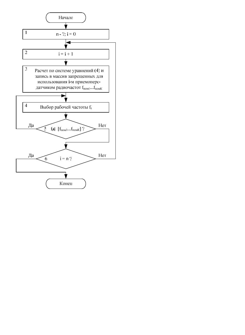
Разработанный по предложенной методике ал-
горитм выбора рабочих частот при подготовке к ра-
боте и в начале работы комплекса показан на рис. 1,
где:
1. Определяется количество n работающих
приёмопередатчиков в составе ППК и обнуляется
счетчик i номера приёмопередатчика.
2. Осуществляется переход к следующему
приёмопередатчику.
3. Проводится расчёт по системе уравнений (4) и
запись в массив запрещённых для использования i-м
приёмопередатчиком радиочастот: f
пом1
… f
помК
.
4. Выбирается рабочая радиочастота f
i
i-ого
приёмопередатчика.
5. Выбранная радиочастота f
i
сравнивается с
массивом рассчитанных запрещённых радиочастот
[f
пом1
… f
помК
]. При совпадении выбранной радиочас-
тоты с одной из запрещённых радиочастот, частота f
i
выбирается заново. При отсутствии совпадения i-ый
приёмопередатчик начинает работать на выбранной
частоте.
6. Если проверка значения счётчика i показывает, что
i<n, то процедура повторяется для следующего
305
приёмопередатчика. При i=n работа алгоритма за-
кончена.
Рис. 1. Обобщённый алгоритм определения
рабочих частот при подготовке к работе комплекса/
Для исключения конфликтной ситуации между
приёмопередающим оборудованием разных частот-
ных каналов в процессе эксплуатации изменение
рабочих частот должно проводиться с исключением
из списка рабочих частот комбинационных. В этом
случае i-ому, перестраиваемому по радиочастоте,
приемопередатчику присваивается последний поряд-
ковый номер n; остальным приемопередатчикам по-
рядковые номера от 1 до (n-1). По системе уравнений
(4) проводится расчет и запись в массив запрещен-
ных для использования n-ым приемопередатчиком
радиочастот f
пом1
…f
помК
. Новая рабочая частота n-го
приемопередатчика выбирается на основании дан-
ных о запрещенных к использованию радиочастот из
рассчитанного массива данных частот.
Практические исследования
Для обеспечения ЭМС при разработке ППК
должны учитываться характеристики, как приёмных,
так и передающих систем. В настоящее время наибо-
лее высокие показатели достигнуты в радиостанции
серии 4200 фирмы Rohde&Schwarz, Германия, пред-
назначенной для авиадиспетчерских служб. Для оп-
ределения степени повышения эффективности рабо-
ты мобильного совмещённого ППК с изменяемым
частотным планом при использовании методики раз-
работана радиостанция с показателями, не уступаю-
щими показателям радиостанции фирмы
Rohde&Schwarz [2].
В исследовании на основании характеристик ра-
диостанции учитывается, что мощность излучения
передатчика, наводимая в передающую антенну, со-
ставляет 10 Вт. Чувствительность приёмной системы
по выходу приёмной антенны из-за использования
фильтровых и развязывающих устройств в составе
комплекса ухудшается до 2 мкВ. Комплекс работает
в диапазоне частот от 112 до 156 и от 225 до
400 МГц, шаг сетки рабочих частот составляет
25 кГц; спектральная плотность шума передатчика в
полосе 1 Гц: ниже минус 153 дБ относительно уров-
ня основного излучения; уровень внеполосных со-
средоточенных излучений меньше уровня мощности
передатчика на 105 дБ; блокирование чувствитель-
ности приемника при отстройках на ± 1 МГц состав-
ляет 53 мВ; подавление продуктов интермодуляции
3-го порядка в передатчике при отстройках помехи
на ± 175 кГц и развязке 26 дБ: 58 дБ. В комплексе
может быть задействовано до семи приёмопередаю-
щих станций, расстояние между приёмной и пере-
дающей антеннами не должно превышать 40 м.
Расчеты показывают, что при расстоянии между
приемной и передающей антеннами равном 40 м,
такие показатели радиостанции, как плотность шума
передатчика и уровень внеполосных сосредоточен-
ных излучений не оказывают влияния на принимае-
мый сигнал. Проблема блокирования чувствительно-
сти приёмника при воздействии на его вход мощного
сигнала от работающего на другой радиочастоте пе-
редатчика комплекса решается аппаратными мето-
дами, в том числе за счет применения радиочастот-
ных с высокой избирательной способностью и ма-
лыми потерями в полосе пропускания радиочастот-
ных фильтров [3].
Существование проблемы обеспечения ЭМС в
ППК обусловлено показателями радиостанции по
подавлению продуктов интермодуляции 3-го поряд-
ка в передатчике. Расчеты показывают, что даже с
применением фильтрующих систем, расстояние ме-
жду приёмной и передающей антенной должно быть
не менее 2,14 км. Применение только аппаратных
методов не позволяет ослабить интермодуляционные
составляющие на требуемую величину, особенно в
случае пространственного разноса между приёмной
и передающей антеннами порядка 40 м.
Предлагаемая методика позволяет рассчитывать
и исключать из частотного плана ППК комбинаци-
онные радиочастотные составляющие, в том числе и
интермодуляционные частоты.
Как видно из формулы (1), кроме интермодуля-
ционных составляющих 3-го порядка возникает

306
множество интермодуляционных составляющих n-
ого порядка. Поэтому при расчетах обязательно учи-
тывать не только интермодуляционные составляю-
щие 3-го порядка, но и более высоких порядков. Но,
чем выше порядок составляющей, тем больше она
подавлена. Проведённые эксперименты показали,
что интермодуляционные составляющие 9-го поряд-
ка при пространственном разносе в 40 м подавлены
уже настолько, что при расчётах возможен учёт ин-
термодуляционных составляющих до 8-го порядка
включительно.
По предложенным алгоритмам и системе урав-
нений (4) была разработана программа, учитываю-
щая: количество приёмопередатчиков в ППК, диапа-
зон рабочих радиочастот, шаг частотной сетки, по-
рядок образующихся комбинационных частотных
составляющих. С помощью разработанной програм-
мы были получены результаты, сведённые в табл. 1.
Таблица 1
Расстояние между при-
емной и передающей
антеннами, м
40 120 380
Порядок учитываемых
интермодуляционных
составляющих
8 7 6
1+1
6 /
0,07 %
3 /
0,03 %
2 /
0,02 %
2+1
46 /
0,53 %
33 /
0,38 %
21 /
0,24 %
3+1
298 /
3,4 %
221 /
2,52 %
134 /
1,53 %
4+1
1159 /
13,2 %
665 /
7,6 %
403 /
4,6 %
5+1
3532 /
40,3 %
1910 /
21,8 %
998 /
11,4 %
Количество
приемопередат-
чиков в составе
ППК: число уже
работающих
приемопередат-
чиков + один
вводимый в ра-
боту приемопе-
редатчик
6+1
8760 /
100 %
8043 /
91,8 %
3633 /
41,5 %
Количество запрещенных
для использования частот:
абсолютное число / в про-
центах к общему числу
частот 8760
В табл.1 приведено максимальное количество
комбинационных, запрещённых к использованию
радиочастот при работе определенного количества
приёмопередатчиков в составе комплекса на соот-
ветствующем удалении приёмной и передающей ан-
тенн друг от друга. При моделировании не учитыва-
лись параметры, особенности, характеристики при-
ёмных, передающих устройств и приёмопередающей
системы в целом, обеспечивающие дополнительную
развязку как между передатчиками, так и между
приёмниками и передатчиками комплекса, следстви-
ем чего является уменьшение числа запрещённых к
использованию радиочастот.
Как видно из табл. 1, при заданном расстоянии
между антеннами 40 м существует два крайних слу-
чая. В первом случае в комплексе задействовано ми-
нимальном количество приемопередатчиков в систе-
ме, равное двум (1+1) и поэтому количество запре-
щённых к использованию радиочастот очень мало и
не превышает 0,1 % от общего количества исполь-
зуемых радиочастот. Во втором случае задействова-
но количество приёмопередатчиков, равное семи
(6+1); при нём количество запрещённых радиочастот
составляет 100 % и изменение рабочих частот радио-
станций становится невозможным. В остальных слу-
чаях наглядно показано, что при увеличении количе-
ства задействованных радиостанций резко возрастает
число запрещённых к использованию радиочастот.
Вывод
При соотнесении полученных с помощью про-
граммы результатов с вероятностью выбора операто-
ром запрещённой частоты при смене частоты на-
стройки радиостанции можно заметить, что:
- при малом количестве работающих приемопе-
редатчиков в составе ППК вероятность ошибки опе-
ратором также будет мала и в случае, например, с
тремя приёмопередатчиками (2+1) будет составлять
0,53 %. При применении разработанной программы
повышение эффективности работы ППК в целом
будет незначительно;
- в случае использования большего количества
приёмопередатчиков вероятность ошибки операто-
ром возрастает нелинейно. Закон возрастания близок
к экспоненциальному. Уже при шести задействован-
ных приёмопередатчиках вероятность выбора опера-
тором запрещенной радиочастоты составляет более
40 %. В этом случае расчёт и исключение из плана
запрещённых радиочастот с помощью разработанной
программы будет значительно экономить время пе-
рестройки на другую частоту, что значительно по-
вышает эффективность работы ППК.
В настоящее время подход, при котором коли-
чество радиоканалов в приёмопередающем комплек-
се должно быть максимальным, наиболее рациона-
лен и экономически выгоден. При максимальном
количестве входящих в состав ППК радиостанций
разработанная методика позволяет существенно по-
высить эффективность работы совмещённого приё-
мопередающего комплекса с перестраиваемым час-
тотным планом.
Литература
1. Долуханов, М.П. Распространение радиоволн
/ М.П. Долуханов. – М.: Связь, 1965. – 400 с.
2. http://www2.rohde-schwarz.com/en/products/
sеcure_communications/los_radiocommunications/Serie
s4200.html
3. Патент на полезную модель №88878 Россий-
ская Федерация, МПК Н03Н 7/00. Полосно-
пропускающий LC-фильтр на четырех связанных
контурах / Ф.И. Векслер, И.С. Прохоров –
№ 2009123894; заявл. 22.06.2009; опубл. 20.11.2009.

307
THE IMPROVING OF THE OPERATING EFFECTIVENESS
OF RADIO COMMUNICATION TRANSMIT-RECEIVING COMPLEXES
WITH VARIABLE FREQUENCY
I.
S.
P
ROKHOROV
,
R
USSIA
“The design office of a radio communication of Vladimir”, ivpc@mail.ru
The research task is to improve the operating effec-
tiveness of multichannel transceiving complexes
(TxRxC) with variable frequencies by taking into ac-
count the prohibition on using of the combination radio
frequencies f
comb
, that originate through interference of
adjacent transmission equipment. The supporting the
EMC is especially acute in development of communica-
tion TxRxC. It is therefore necessary:
1. To ensure the trouble-free operation against the
background of intense radio waves of TxRxC transmit-
ters due to limited spatial separation of transmitting and
receiving antennas.
2. To keep constant records of the combination ra-
dio frequencies changing the operational frequencies in
TxRxC.
The suggested technology allows improving TxRxC
operating effectiveness by keeping constant records of
the combination radio frequencies. The special feature of
this technology is that the calculation of f
comb
is made
before the new transceiver initiating or before frequency
variation of working transmitters. The combination fre-
quency f
comb
is deduced from equation:
n1-n21comb
fzfy...fbfaf ⋅+⋅++⋅+⋅=
, (1)
where a, b, y, z are integers; f
1
, f
2
, f
n-1
, f
n
are operating
frequencies of transmitters, Hz.
If plugged transmitter is operated on the frequency
f
n
, and f
comb
becomes equal to f
1
, f
2
…f
n
, then f
n
– the
prohibited frequency, hence:
≠
≠
≠
−
.ff
,ff
...
,ff
ncomb
1ncomb
1comb
(2)
Including (1) into the system of equations (2) we get:
⋅+⋅++⋅+⋅≠
⋅+⋅++⋅+⋅≠
⋅+⋅++⋅+⋅≠
−
−−
−
.fzfy...fbfaf
,fzfy...fbfaf
...
,fzfy...fbfaf
n1n21n
n1n211n
n1n211
(3)
Relative to f
n
=f
comb
, a set of f
comb
is found:
−⋅++⋅−=
⋅−++⋅−=
⋅++⋅−−=
−
−−
−
).1z/()fy...fa(f
,z/)f)1y(...fa(f
...
,z/)fy...f)1a((f
1n1)n(comb
1n1)1n(comb
1n1)1(comb
(4)
Radio station that was highly competitive with radio
station series 4200 production by Rohde & Schwarz was
developed for determining the improvement of the oper-
ating effectiveness of TxRxC combine with variable
frequencies in case of using such technology.
The supporting EMC in TxRxC is a problem that is
conditioned by the third and higher order combination
frequency of absorption index in transmitters. The physi-
cal experiment showed that f
comb
of the ninth order was
so suppressed in 40 m of spatial separation that they can
not be taken into consideration.
A program was developed according to this tech-
nology that takes into account the amount of transceivers
in TxRxC, the working frequency range, the array fre-
quency pitch, the order of combination frequencies.
The results are given in the Table 1.
Table 1.
The distance between anten-
nas, m
40 120 380
Ordering the combination
frequencies
8 7 6
1+1 0,07 %
0,03 %
0,02 %
2+1 0,53 %
0,38 %
0,24 %
3+1 3,4 % 2,52 %
1,53 %
4+1 13,2 %
7,6 % 4,6 %
5+1 40,3 %
21,8 %
11,4 %
Amount of trans-
ceivers+ starting
work of transre-
ceiver
6+1 100 % 91,8 %
41,5 %
Quantity f
comb
in percent-
age to the general number
of frequencies
The correlation of the received results with prob-
ability of the choice by operator of the forbidden fre-
quency allows drawing the following conclusions:
- If the quantity of working transceivers will be
small the probability of an error will be small also and
the increase of the efficiency of the performance of
transceiving complexes as a whole will be insignificant;
- In case of use of the large amount of transceivers
the probability of an error increases not linearly. Already
in a case with six transceivers the probability of an error
makes up more than 40 %.
At present the approach which supposes the maxi-
mum quantity of radio channels in transceiving com-
plexes is the most rational and economic. In case of use
of the maximum quantity of the radio stations in the
structure of transceiving complexes the developed tech-
nology allows raising essentially the efficiency of the
performance of the combined complex with the recon-
structed frequency plan.

308
UNIVERSAL TECHNIQUE FOR INTERFERENCE RESPONSE
RECOGNITION FROM RESULTS OF RADIO RECEIVER’S
DOUBLE-FREQUENCY TESTING
E
UGENE
V.
S
INKEVICH
,
B
ELARUS
Belarusian State University of Informatics and Radioelectronics, e-mail: emc@bsuir.by
Abstract. For analysis of nonlinear effects in radio receivers, a technology of double-frequency testing is
developed and put into operation. This technology allows one to easily detect all existing linear and nonlin-
ear paths that cause interference at the receiver output, including areas of spurious generation in presence of
powerful interfering signals. In this paper, a universal technique for recognition of the receiver’s interference
responses detected by the double-frequency testing is proposed. The technique is obtained by developing the
method of frequency measurement and solving the system of linear algebraic equations. In order to validate
the proposed technique, the recognition of nonlinear effects in Schäffner SMR 4518 receiver from measured
double-frequency diagrams is performed. Validation results indicate a high efficiency of the technique: all
detected responses (desired, spurious, and intermodulation of orders up to 41) were recognized correctly.
Introduction
The technology of double-frequency testing (DFT)
is a very effective and practically-proved tool for analy-
sis of radio receiver susceptibility to interference at the
antenna input [1, 2, 3]. Implementation principles and
operation results of an automated double-frequency test
system (ADFTS) based on this technology are consid-
ered in [1, 2].
According to the DFT technology, a radio receiver
is usually tested in three stages: 1) detection of interfer-
ence responses, 2) recognition of the detected responses
(i.e., determination of paths and effects that cause inter-
ference at the receiver output), and 3) measurement of
the responses’ parameters [1, 2].
When developing the ADFTS of a new generation
[4], it was necessary to provide its compatibility with
USA Military Standards (MIL-STDs). This toughens the
requirements to the functionality of the response recog-
nition because, in compliance with the Standard [5], the
receiver under test may have up to three frequency con-
versions.
In ADFTS of the previous generations, the combi-
nation of the following two methods was mainly used for
the recognition of detected responses: 1) estimation of
angles between the response image and the axes of dou-
ble-frequency diagram (DFD); 2) recognition of specific
groups of response images in DFD [1, 2].
The recognition technique based on the above-
mentioned combination of methods has the following
drawbacks: 1) identification problem is solved partially
(the technique is able to recognize only coefficients held
by the test signal frequencies); 2) the image groups in
DFD are recognized heuristically (by hands), and several
peculiar puzzles exist, especially for receivers having
more than one frequency conversion (ref. Section 2).
The objective of this paper is to develop a universal
and fully-automated technique for recognition of inter-
ference responses of receivers which may have up to
three frequency conversions.
The paper is organized as follows: the problem of
response recognition is stated in Section 1, then the
drawbacks of known recognition methods are analyzed
(Section 2), and finally, a new recognition technique is
proposed (Section 3) and validated (Section 4).
Problem of Response Recognition
Generation of responses (desired, spurious, inter-
modulation ones) in radio receiver can be described by
the following equation, which is referred to as channel-
ing equation:
0
2211
=+⋅+⋅ Cfzfz
,
outLONL
ffC −=
,
, (1)
=⋅+⋅+⋅
=⋅+⋅
=⋅
=
=
,3,
;2,
;1,
;0,0
352413
2413
13
,
fcLOLOLO
fcLOLO
fcLO
fc
LONL
Nfzfzfz
Nfzfz
Nfz
N
f (2)
where
54321
,,,,
zzzzz are integer coefficients;
1
f and
2
f stand for the frequencies of the first and second test
signals at the receiver input, respectively;
LONL
f
,
denotes
the frequency of a (existing or imaginary) combination
component created from signals of the local oscillators;
out
f is the carrier or intermediate frequency of the de-
sired signal at the receiver output under analysis (for
direct conversion receiver it is necessary to take the last
intermediate frequency equal to zero);
1LO
f ,
2LO
f ,
3LO
f – frequencies of the first, second, and third local
oscillator, correspondingly;
fc
N is the number of fre-
quency conversions in the receiver.
Equation (1) generalizes the spurious and inter-
modulation response generation equations given in stan-
dards [5, CS108/109, CS110/111], [6, GOST 22580-84,
GOST 12252-86, etc.].
In compliance with (1), each response is displayed
as a straight line on the DFD in coordinates
),(
21
ff .
The problem of response identification (recognition) is
309
to find values of the coefficients
51
...zz
in channeling
equation (1) from the given image of response in the
DFD. Having these values, the user can determine the
most probable physical effects which cause the emer-
gence of the nonlinear interference corresponding to the
recognized response.
Analysis of Response Recognition Methods
Known methods of response recognition are con-
sidered in [1, 2]. Let us analyze their drawbacks:
1) Method of slope angle [1, Section IV, method 1]:
1.1) Capabilities of the method are limited: without
additional measurements, it is possible to determine only
the coefficients
1
z
and
2
z
; the coefficient held by the
frequency of one of the local oscillators (as a rule,
3
z
)
can be estimated by changing the tuning frequency of the
receiver under test (this requires to repeat the measure-
ment of the double-frequency characteristic once again);
the coefficients held by the frequencies of the remaining
local oscillators can not be determined by the method.
1.2) The method accounts for the slope angle of the
response image, but it does not take into account the
position (displacement) of the image – this may cause
errors in recognition. For example, even-order inter-
modulation responses of the kind
)0,,(),,(
321
mmzzz −=
,
...,2,1
±
±
=
m
have equal slope angles
°
=
45
α
[1,
Fig.6(e)], therefore the method is unable to distinguish
such responses from each other.
2)
Method of patterns’ (specific groups of response
images) recognition [1, Section IV, method 2]:
2.1)
The method is not always able to solve the ba-
sic problem – to recognize a single image of response
(one arbitrary line in DFD). Let us give examples of
problematical situations: a) most of the specific groups
are recognized by their appearance at the point of inter-
section of component parts (response images), but that
point may be located outside of the DFD’s measurement
area
)},(),,{(
max2min2max1min1
ffff
; b) some response
images being parts of a specific group may be fully or
partially invisible (this may cause wrong recognition of
the group’s order).
2.2)
For receivers having more than one frequency
conversion, the position of several specific groups
(nodes of order higher than one) may be unobvious – this
complicates their recognition and may cause errors.
That is why the method can be used as an additional
method only, although it is very convenient for heuristic
analysis of DFD by human-operator.
3)
Method of frequency measurement and solving
the system of linear algebraic equations (SLAE) [1, Sec-
tion IV, method 3]:
3.1)
The number of equations in the system is rig-
orously defined – it is equal to the number of unknown
coefficients
51
...zz
, so we get
2+
fc
N
equations –
ref. (1) and (2). This limits the recognition accuracy by
the errors of one-shot measurements.
3.2)
The system of equations is solved in real num-
bers and the obtained values of coefficients
51
...zz
are
rounded to the nearest integers, but such approach does
not guarantee that the best integer solution will be
achieved.
3.3)
Additional equipment is needed for measure-
ment of frequencies of local oscillators, test signals, and
receiver-under-test output signal.
4)
Method of modulation parameters’ comparison
between the input test signals and the output signal [1,
Section IV, method 4]:
4.1)
Limited capabilities (ref. item 1.1).
4.2)
Increased requirements to the measuring gen-
erators because the test signals must have user-defined
parameters of modulation.
4.3)
Additional equipment is needed for measure-
ment of the output signal’s modulation parameters.
5)
Method of frequency change rate comparison be-
tween the fast-changed test signal and the output signal
[1, Section IV, method 5]:
5.1)
Limited capabilities (ref. item 1.1).
5.2)
Additional equipment is needed for measure-
ment of the output signal’s frequency change rate.
5.3)
For digital frequency sweep, the method can
not be used directly and requires improvement.
5.4)
The method imposes constraint on the test sig-
nal’s frequency change rate for analog sweep (or on the
frequency change step for digital sweep).
As follows from the considered drawbacks, the only
method that is able to solve the recognition problem
completely (i.e., to find all the coefficients
...,,
21
zz
of
an arbitrary response for receiver having any number of
frequency conversions) is “Method of frequency meas-
urement and solving SLAE” [1, Section IV, method 3].
Proposed Recognition Technique
In this paper, we propose a recognition technique
which is obtained by development of the SLAE method
[1, Section IV, method 3] in the following directions:
1) In order to eliminate the drawback given in item
3.1) of Section 2, i.e., to improve the precision of identi-
fication by averaging the results of a large quantity of
measurements, we propose to use an overdetermined
SLAE of the kind (3) and to solve it in the least-squares
sense. For example, as it follows from (1) and (2), we get
the following SLAE if
3=
fc
N
:
==⋅+
+⋅+⋅+⋅+⋅
,...,2,1,
,,35
,24,13,22,11
rpioutiLO
iLOiLOii
Niffz
fzfzfzfz
(3)
where
rp
N
denotes the number of recognition points
);;;;;(
,,3,2,1,2,1 ioutiLOiLOiLOii
ffffff
in which the simul-
taneous measurement of frequencies is performed;
i
is
the index of the recognition point under consideration.
The number of equations in SLAE (3) is arbitrary and it
is equal to the number
rp
N
of recognition points.
2) High performance of modern PCs makes it pos-
sible to remove the drawback given in item 3.2) of Sec-
tion 2 in the simplest way: in this paper, the solution of
SLAE is found by exhaustive search through all potential
solutions (i.e., integer combinations
),,,,(
54321
zzzzz
)
of order not higher than the maximal recognition order
max
M
specified by the user:

310
.||,0||||
,,...,2,1,0,,,,
max
5
1
21
max54321
Mzzz
Mzzzzz
k
k
≤≠+
±±±=
∑
=
(4)
Even in the most complicated situation (receiver has
three frequency conversions and
50
max
=M
) the time of
solving the SLAE by the considered technique on PC
Pentium IV does not exceed 5 seconds, which is quite
acceptable for practice.
3) To eliminate the drawback given in item 3.3) of
Section 2, the SLAE method is expanded to the case of
recognition without frequency measurement. In that
case, instead of the results of simultaneous measurement
of all or several frequencies
;;;;(
,2,1,2,1 iLOiLOii
ffff
);
,,3 ioutiLO
ff
at every recognition point, the following
values are used: a) nominal values of the measuring gen-
erators’ frequencies
i
f
,1
and
i
f
,2
at each recognition
point and b) nominal or singly-measured values of the
frequencies
);;;(
321 outLOLOLO
ffff
which are considered
to be the same for all recognition points.
4) Practical application of the above-described im-
provements in the SLAE method has shown an important
drawback: the obtained solution (recognized response
line) is not always located in the nearest possible way to
the image of the response under recognition in the DFD
(as a result, the recognized response line may move
away from the line under recognition when the maximal
recognition order
max
M
is increased). Therefore, the
criterion of optimization (solving the SLAE) is changed:
instead of sum of squares of residuals, the geometrical
criterion “Sum of squares of distances (by perpendicular)
from the recognition points to a recognized response line
on the DFD” is used.
Squared distance from
i
-th recognition point
);(
,2,1 ii
ff to the recognized response line (1) can be
given by [7, eq. (2.3-1)]
rp
ii
i
Ni
zz
Cfzfz
...,2,1,
)(
)(
2
2
2
1
2
,22,11
2
=
+
+⋅+⋅
=
δ
. (5)
So the optimization criterion can be represented as
min,),,,,();,,(
,][
1
54321543
1
2
,22,11
2
2
2
1
1
2
→≡
+⋅+⋅⋅
+
==
∑∑
==
zzzzzJzzzCC
Cfzfz
zz
J
rprp
N
i
ii
N
i
i
δ
(6)
where C is defined in compliance with (1) and (2).
If at least one of the frequencies
};;;{
321 outLOLOLO
ffff is measured at each recognition
point, then the value of C varies from one recognition
point to the other one, i.e., ),,(
543
zzzCC
i
≡
; therefore,
the geometrical interpretation of the criterion (6) be-
comes approximate (it can be considered as approximate
one, because the changes in frequencies
};;;{
321 outLOLOLO
ffff with recognition point are much
less than in frequencies
1
f and
2
f ).
5) The SLAE method is expanded to the situation in
which there is no information about the internal configu-
ration of the receiver under test: if the frequencies of
local oscillators are unknown, then one real-valued pa-
rameter
LONL
f
,
, which is defined in (2) and which takes
into account all frequency conversions in the receiver, is
used for response recognition instead of integer parame-
ters
43
, zz , and
5
z . Integer coefficients
1
z and
2
z
(which are held by the test signal frequencies) are
searched in compliance with (4), and the real value of
LONL
f
,
(which may also be negative) is calculated in
such a manner to minimize the geometrical criterion (6)
under given
1
z and
2
z .
It is easy to extend the proposed recognition tech-
nique to the case of arbitrary number of frequency con-
versions in the receiver under test.
Validation of Proposed Recognition Technique
In order to validate the proposed technique, the rec-
ognition of nonlinear effects in Schaffner SMR 4518
receiver is performed on the base of measurement results
presented in [8].
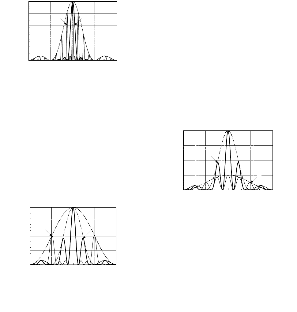
In Fig. 1, a DFD measured under the following
conditions is given. Parameters of the receiver: tuning
frequency GHzf
t
2
=
; test signals are fed to the antenna
input and the response signal is taken from the second
intermediate frequency output
2IFout
ff
=
; dB3
−
band-
width is MHzf
IF
5.2
2
=∆
; frequencies of local oscilla-
tors are GHzf
LO
886.2
1
=
and MHzf
LO
841
2
=
; inter-
mediate frequencies are MHzf
IF
886
1
=
and
MHzf
IF
45
2
=
. Parameters of the measurement: the
same frequency sweep range
GHz]2.2,8.1[
is set for
both test signals; frequency resolution is 101 points for
1
f
(step
MHzf 4
1
=∆
) and 1001 points for
2
f
(step
kHzf 400
2
=∆
); unmodulated test signals of equal levels
dBmPP 0
21
==
are used; analysis band of the receiver
output signal is
MHz]60,30[
. Parameters of visualiza-
tion: the output signal’s minimum level displayed in
DFD
dBmP 66
min
−=
is
dB5.1
above the noise level.
All the responses observed in Fig. 1 are successfully
recognized by the use of the proposed technique. Fre-
quencies of local oscillators were not measured, and
their nominal values given above are used instead. Some
results of the recognition are shown in Fig. 2: the desired
response, for which
)0,1,1,1,0(),,,,(
54321
−−==
zzzzzz
r
,
is marked as “DR”; the other responses designated in
Fig. 2 as (“0”, “1”, “2”, “3”) belong to a 4th-order node
and have coefficients
)0,1,3),(,(
−−−−=
mMmz
n
r
,
where
n
M
is the order of node
)4||||(
21
=+=
zzM
n
and
m
is the number of line as designated in Fig. 2
)...,1,0(
n
Mm
=
. A spurious response corresponding to
4
==
n
Mm
is not observed in Fig. 1 because of low
resolution of the DFD for the frequency
1
f
(101 points
for
1
f
as against 1001 for
2
f
). In contrast to [1, Fig.
6(d)], the 4th-order node in Fig. 2 is formed by involving
the 3rd harmonic of the local oscillator (not the 4th har-
monic).
The marker line method is used for recognition: by
moving the recognition markers (designated as circles in
Fig. 2) with the mouse, it is necessary to superimpose the
marker line on the recognized response image in DFD;
after each movement of either marker, the coefficients
51
...zz
in equation (1) are recalculated (by the proposed