Xin Q. Diesel Engine System Design
Подождите немного. Документ загружается.

© Woodhead Publishing Limited, 2011
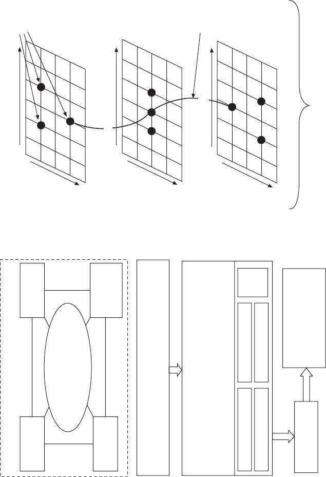
A design problem in four-dimensional space
Hardware
configuration
Engine speed
and load
At critical speed load modes, under normal and extreme
ambient temperature and altitude, produce parametric
sensitivity design charts or optimization charts, choose
design spec to meet constraints or at optimum trade-off
for all hardware configuration options
Set design constraints/limits (maximum cylinder P, turbo
speed, compressor outlet T, exhaust manifold T, coolant
heat rejection; emissions recipe requirements; BSFC target)
Ambient
temperature
and altitude
Hardware
design spec
Compare BSFC, hardware
cost and complexity, transient
performance at
fixed emissions
Others
(valve,
etc.)
EGR configurations
Cooling configurations
Aftertreatment
Turbo configuration
Screen to choose
best configuration
Expand design spec
to entire speed–load
domain at all ambient/
altitude (conduct virtual
calibration)
Repeat the above for all ambient and altitude conditions
At critical speed
load mode 3
(driving part load)
The overall
winning
configuration
At critical speed
load mode 2
(peak torque)
At critical speed
load mode 1
(rated power)
Optimized
design spec
for each
configuration
Hardware configurations
Hardware design and
calibration specs
Hardware design and
calibration specs
Hardware design and
calibration specs
Hardware configurations
Hardware configurations
15.1 Design space and design process of engine system specification.
Diesel-Xin-15.indd 942 5/5/11 12:07:05 PM
943Diesel engine system specification and subsystem interaction
© Woodhead Publishing Limited, 2011
and cooling. Sensitivity design charts are produced at this stage. At each speed
and load mode, the DoE factors may include some or all of the following:
exhaust restriction, charge air cooler size, EGR cooler size, compressor or
turbine efciency (if turbocharger maps are not used) or efciency multiplier
(if turbocharger maps are used), turbine effective area, turbine wastegate
opening, EGR circuit ow restriction coefcient, certain design factors
affecting engine volumetric efciency (e.g., valve size, valve timing, port
ow discharge coefcient), and start-of-combustion or start-of-injection
timing. The analysis output includes critical instantaneous parameters
such as the in-cylinder details and the gas ow pulsation in the pipes. The
output also includes all the cycle-average parameters describing the entire
engine system performance such as air–fuel ratio, EGR rate, oxygen mass
fraction, BSFC, peak cylinder pressure, peak cylinder bulk gas temperature,
pumping loss, engine delta P, volumetric efciency, manifold pressures and
gas temperatures, heat rejections, cooler effectiveness and ow restriction,
turbocharger ow rate, pressure ratio and temperatures, and turbocharger
efciency (if turbocharger maps are used).
In the concept design phase, technology evaluation is important in
order to choose the right path for the engine product development. Diesel
engine technology reviews and evaluations are provided by Merrion (1994),
Regueiro and Chen (1997), Chen et al. (1997), Khair (1997), Hikosaka
(1997), Schindler (1997), Hountalas (2000), and Conley and Taylor (2002).
Diesel engine research program reviews are summarized by Rickeard et al.
(1996), Eberhardt (1999), Singh et al. (2000), and Thompson et al. (2004).
System-level design and optimization techniques are described by Page and
Edgar (1998), Burtt and James (2004), Berard et al. (2000), and Fussey et
al. (2001).
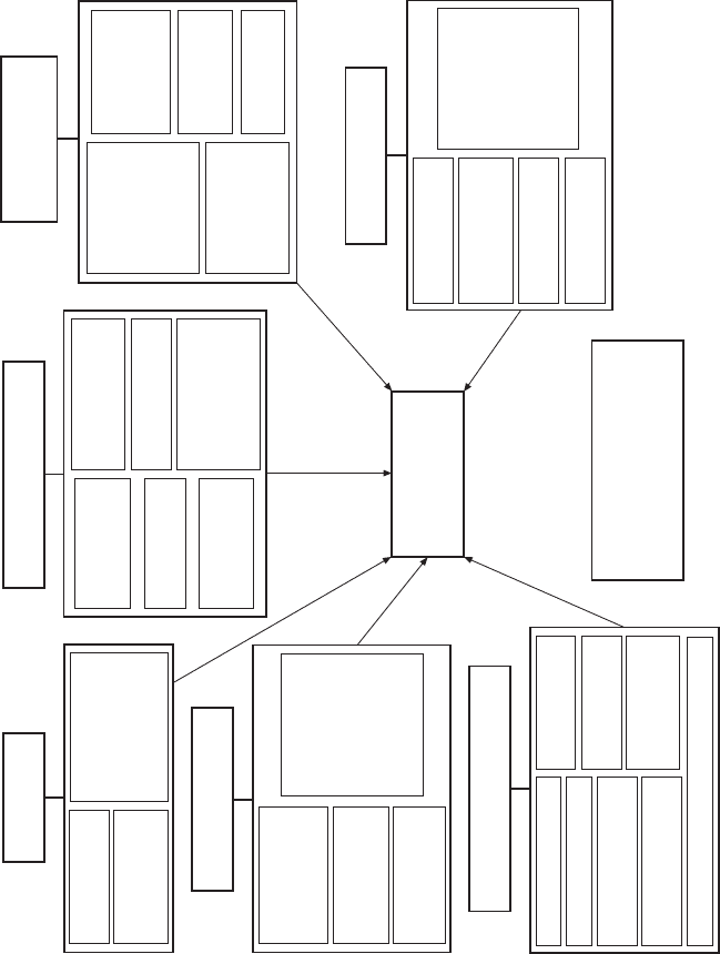
15.2 Roadmap of fuel economy improvement
In the efforts to improve fuel economy, the role of engine system design
is to lead the way in dening a reasonable roadmap and cascade it to each
subsystem to implement design changes. The roadmap, as shown in Fig.
15.2 (for improving a non-optimized high pumping loss engine), usually
consists of six areas: (1) aftertreatment; (2) combustion and fuel system; (3)
mechanical design of cylinder, valvetrain, cylinder head, and manifolds; (4)
turbocharger, EGR, and waste heat recovery systems; (5) mechanical friction
and parasitic losses of accessories; and (6) vehicle drivetrain matching.
Improvements can be made either through incremental change or by adopting
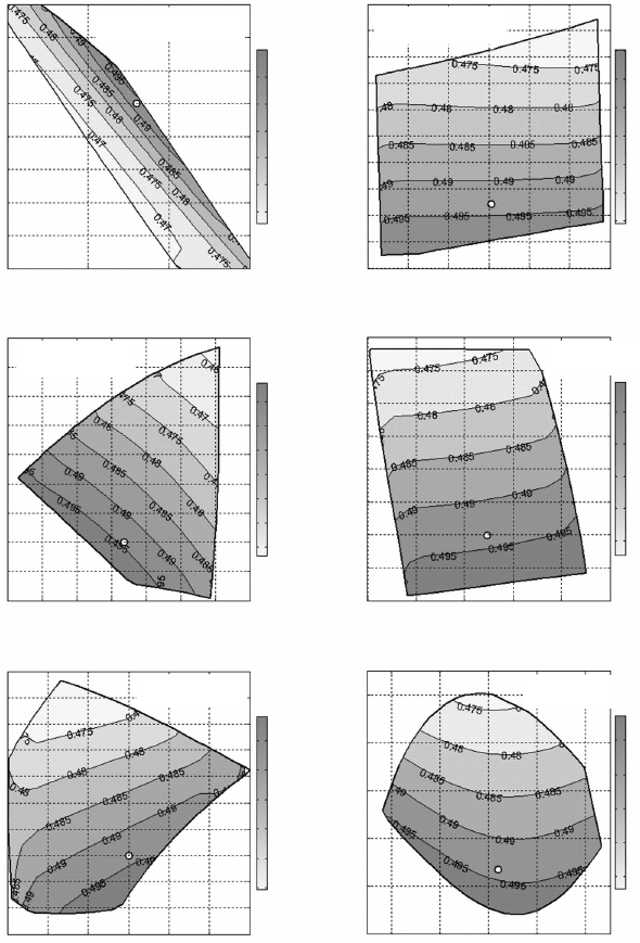
new technologies. Figure 15.3 shows a simulation analysis on the methods
to improve BSFC by improving the design or calibration parameters in the
air system, cooling system, and the combustion system.
Diesel-Xin-15.indd 943 5/5/11 12:07:05 PM
© Woodhead Publishing Limited, 2011
Aftertreatment
(total: 1.5%)
Reduce EGR circuit
restriction (0.5%)
Turbocompounding
(>2%)
Reduce EGR rate in
engine calibration
or combustion (1%)
Increase
EGR cooler
effectiveness (1%)
Cooling fan power
reduction by using
electric fan (3%)
Reduce valvetrain
friction with
softer valve
springs (0.3%)
Increase turbocharger
efficiency to reduce
pumping loss (3%)
Advanced
thermodynamic
cycles (Rankine, or
Brayton, or Sterling)
for waste heat
recovery (6%)
Reduce exhaust
restriction (0.2%)
Reduce DPF
regeneration frequency
and fuel consumption
penalty with more
passive regeneration
and larger filter
capacity (1%)
Reduce DPF
regeneration NO
x
penalty (0.3%)
Turbocharger, EGR and waste heat
recovery systems (total 13.5%)
Mechanical friction and
parasitic accessory loss
reduction (total 8%)
Reduce piston
skirt and ring
friction by 10–20%
with optimum ring
profile and tension
design and lower
cylinder
bore distortion (2%)
Power reduction
of water pump,
fuel pump and oil
pump, or smart
cooling (0.7%)
Change to low-
viscosity oil (2%)
Vehicle and drivetrain
matching (total 9%)
Increase drivetrain
efficiency, change
tire size, reduce
tire-road rolling
friction coefficient,
reduce vehicle
frontal area,
reduce vehicle
aerodynamic drag
coefficient (1%)
Reduce ROA and
recirculation (1%)
Change transmission
shift map (5.5%)
Vehicle braking
energy recovery
Change rear axle ratio
and transmission gear
ratios (1.5%)
Total vehicle fuel
economy improvement
in typical driving cycle
53%
Notes:
(1) Data in parentheses indicate fuel
economy improvement percentage.
(2) Need to minimize the penalty on
drivability and transient acceleration
Combustion and fuel
injection systems (total: 4%)
Engine-out soot
reduction to reduce
DPF regeneration
frequency (0.5%)
Swirl reduction to
reduce cylinder heat
rejection loss (0.5%)
Optimize calibration
to advance fuel
injection timing (1%)
A/F ratio reduction
to reduce pumping
loss through better
combustion bowl,
fuel injection
nozzle, higher fuel
injection pressure,
better or variable
swirl ratio (2%)
Mechanical design of cylinder,
valvetrain, cylinder head and
manifolds (total 17%)
Reduce displacement (3%)
Cylinder deactivation (8%)
Bigger intake and exhaust valves (1%)
Variable compression
ratio via VVA (2%)
Increase intake port
flow coefficient (1%)
Lower exhaust port
heat rejection (1%)
Less restrictive
exhaust manifold
(0.5%)
Aggressive cam profiles
for higher volumetric
efficiency (0.5%)
15.2 Example of fuel economy improvement roadmap.
Diesel-Xin-15.indd 944 5/5/11 12:07:05 PM
945Diesel engine system specification and subsystem interaction
© Woodhead Publishing Limited, 2011
A/F ratio
Overall two-stage turbocharger efficiencyOverall two-stage turbocharger efficiency
Overall two-stage turbocharger efficiency
HP turbine effective area (cm
2
)
Overall HP turbocharger efficiency
28
27
26
25
24
23
22
21
20
0.49
0.48
0.47
0.46
0.45
0.44
0.43
0.42
0.41
0.4
0.49
0.48
0.47
0.46
0.45
0.44
0.43
0.42
0.41
0.4
0.39
0.5
0.495
0.49
0.485
0.48
0.475
0.47
0.495
0.49
0.485
0.48
0.475
0.47
0.465
0.495
0.49
0.485
0.48
0.475
0.47
0.5
0.495
0.49
0.485
0.48
0.475
0.47
0.495
0.49
0.485
0.48
0.475
0.495
0.49
0.485
0.48
0.475
3
2.95
2.9
2.85
2.8
2.75
2.7
2.65
2.6
2.55
0.47
0.46
0.45
0.44
0.43
0.42
0.41
0.4
0.52
0.5
0.48
0.46
0.44
0.42
BSFC (lb/(hp.hr))
BSFC (lb/(hp.hr))
BSFC (lb/(hp.hr))
BSFC (lb/(hp.hr))
BSFC (lb/(hp.hr))
BSFC (lb/(hp.hr))
25 30 35 40
EGR rate (%)
0.4 0.45 0.5 0.55 0.6 0.65 0.7
EGR cooler effectiveness
0 1 2 3 4 5 6
Start-of-combustion timing (degree ATDC)
6.5 7 7.5 8 8.5 9 9.5
LP turbine effective area (cm
2
)
0.6 0.7 0.8 0.9 1 1.1
Total exhaust restriction (inch Hg)
0.18 0.2 0.22 0.24 0.26
Overall LP turbocharger efficiency
Simulation at variable
emissions
Simulation at
fixed emissions
Simulation at fixed
emissions
Simulation at
fixed emissions
Simulation at
fixed emissions
Simulation at
fixed emissions
15.3 Summary on the impact on BSFC at typical part-load operation
(2000 rpm 30% load).
Diesel-Xin-15.indd 945 5/5/11 12:07:05 PM
946 Diesel engine system design
© Woodhead Publishing Limited, 2011
15.3 Critical mode design at various ambient
conditions
15.3.1 System design constraints
In engine system specication design there are two categories of limits,
usually occurring at full load: the hardware design limit and a lower limit
used for the calibration test setting. The necessity for the two limits is based
on the statistical distribution of hardware variations. The ‘nominal’ engine
design or calibration set point (e.g., intake manifold pressure or exhaust
manifold gas temperature) under the standard normal ambient condition
should be lower than the ‘calibration limit’ by a certain margin. The full-load
conditions of the hardware in the system specication need to be designed
below the ‘design limit’ in order to cover the worst ambient conditions in
emissions certication and real-world driving. Different design limits may
occur at different ambient conditions or engine speeds, for example (also
illustrated in Section 3.4.5):
∑ In order to be compliant with the US EPA NTE emission requirements,
the EGR cooler and the charge air cooler need to be sized for sea-level
altitude and hot ambient (e.g., 38°C or 100°F) to reach a target intake
manifold gas temperature.
∑ The compressor inter-stage cooler in a two-stage turbocharger needs
to be sized with a sufcient cooling capacity and an appropriate cooler
sink temperature (i.e., the cooling medium temperature) to ensure proper
operation of the high-pressure-stage compressor under high ambient
temperatures at sea level or high altitude conditions. Specically, the
outlet air temperature of the compressor needs to be below the material
limits of the compressor wheel, the housing, and the charge air cooler
inlet tube.
∑ The engine coolant heat rejection and the associated EGR strategy need
to be designed to ensure that at high altitude and hot ambient (e.g., 38°C)
the engine outlet or radiator inlet coolant temperature does not exceed
the durability limit. High altitude refers to, for example, 1676 meters
or 5500 feet – the US EPA NTE limit, or 10,000 feet in practical real-
world applications.
∑ The turbocharger control and the EGR strategy need to be tailored for
high altitude and hot ambient conditions to ensure that soot emission is
still below the smoke limit with a lower air–fuel ratio. Additionally, the
exhaust manifold gas temperature should be within the limit imposed
by the durability of the cylinder head and the turbine.
∑ The compressor needs to be sized large enough to ensure the turbocharger
speed is still below the maximum limit at high altitude without fueling
derating.
Diesel-Xin-15.indd 946 5/5/11 12:07:05 PM
947Diesel engine system specification and subsystem interaction
© Woodhead Publishing Limited, 2011
∑ The maximum cylinder gas pressure and temperature as well as the peak
heat ux need to be designed below the combined limits of mechanical
and thermal stresses for the power cylinder components.
∑ The turbocharger and EGR controls need to be designed to ensure that
the peak cylinder pressure along the full-load lug curve does not exceed
the structural limit in a cold climate. Moreover, any compressor surge
at cold ambient should be avoided. The full-load lug curve refers to US
SET modes A100, B100, C100, peak torque and rated power.
∑ During the ring and engine braking operations in both steady state and
transient, the exhaust manifold pressure should be below the structural
limit. The engine delta P should be kept below the point where the
exhaust valve oats off the valve seat.
∑ For high EGR engines in extremely humid climates, the intake manifold
gas temperature needs to be designed not to exceed the durability limits
of condensation control and corrosion resistance.
∑ All the hardware design constraints need to be satised during the
maximum engine braking operation.
15.3.2 Design from extreme ambient to standard lab
condition
The ambient conditions used in hardware sizing usually include the
following:
1. Sea-level altitude and normal ambient temperature (e.g., 25°C or
77°F).
2. The US EPA’s heavy-duty emissions NTE limits (sea-level altitude,
from cold ambient to 38°C or 100°F hot ambient).
3. The 1676 meters or 5500 feet altitude, from cold ambient to 30°C or
86°F, with a humidity range.
4. The real-world driving environments (e.g., 5500 feet on a hot day, a
very high altitude level such as 8000–10,000 feet on a hot day, and a
cold ambient condition at sea level, for example –18°C or 0°F).
It is also necessary to consider the following factors: hot air recirculation,
turning on air-conditioning, and the rise-over-ambient elevated compressor
inlet air temperature due to in-vehicle underhood heating.
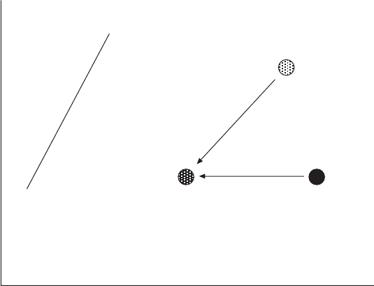
Figure 15.4 shows an example of the system design sequence from
the extreme ambient and in-vehicle conditions to the standard lab engine
condition. The EGR rate required at the hot ambient or high altitude is
affected by the emissions requirement, intake air temperature, air–fuel ratio,
and oxygen concentration. The difference in the required EGR rate between
the sea level and the extreme ambient condition depends on emissions
regulation level, particular engine design, and the fuel system capability.
Diesel-Xin-15.indd 947 5/5/11 12:07:06 PM
948 Diesel engine system design
© Woodhead Publishing Limited, 2011
The achievable EGR rate and air–fuel ratio at the same altitude but different
ambient temperatures are determined by the engine control strategy of the
air system. For example, the VGT vane opening at sea level hot ambient
can be controlled by exhaust manifold pressure or intake manifold pressure.
In the ‘lambda control’, air–fuel ratio is maintained at a constant level at a
given altitude and is controlled by regulating the EGR valve opening.
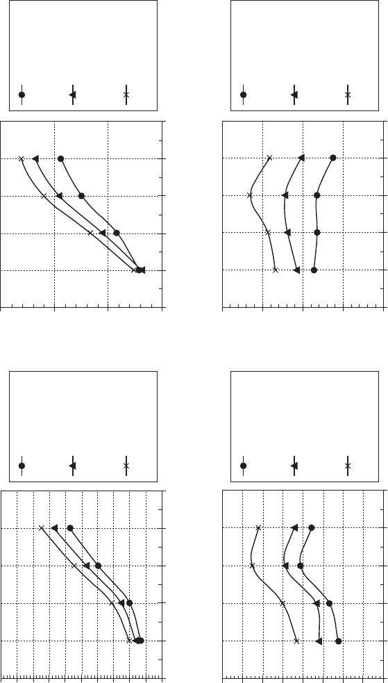
Figure 15.5 shows typical behavior of engine performance at different
ambient conditions at the full-load lug curve. Note that the exhaust manifold
gas temperature and compressor outlet air temperature are higher at the high
altitude and hot ambient condition than the sea level normal ambient condition.
The engine delta P can also be higher if the EGR is reduced and the turbine
wastegate is closed in order to increase the air–fuel ratio at high altitude.
The higher BSFC at the extreme ambient conditions is caused mainly by a
reduction in the indicated power in the compression and expansion strokes
due to the decrease in air–fuel ratio and secondarily affected by the increase
in engine delta P or pumping loss.
15.3.3 Design for varying exhaust flow rate
In addition to the variations in ambient pressure and temperature conditions,
hardware matching is also complicated by the large variations in the EGR
ow and the exhaust restriction in the aftertreatment system. For instance,
15.4 Illustration of engine system design from extreme ambient to
standard lab condition.
Compressor pressure ratio
Compressor map
Surge line (not to scale)
Change wastegate and
EGR valve opening
5500 ft, 86°F ambient,
15°F ROA Emissions
recipe to meet uS EPA
NTE: A/F = 19, EGR =
27%, IMT = 135°F
Sea level, 77°F
ambient, 0°F
ROA. Recipe to
meet uS EPA
FTP:
A/F = 20,
EGR = 32%,
IMT = 130°F
Sea level, 100°F
ambient, 15°F
ROA. Recipe to
meet NTE: A/F =
20, EGR = 29%,
IMT = 150°F
‘lambda control’
(change wastegate
and EGR valve
opening)
Compressor mass flow rate
Rated power
Diesel-Xin-15.indd 948 5/5/11 12:07:06 PM
© Woodhead Publishing Limited, 2011
Heavy-duty diesel engine system design at full load under different ambient temperature and altitude conditions
1000 1200 1400 1600 1800 2000
Engine speed (rpm)
1000 1200 1400 1600 1800 2000
Engine speed (rpm)
1000 1200 1400 1600 1800 2000
Engine speed (rpm)
1000 1200 1400 1600 1800 2000
Engine speed (rpm)
BSFC (lb/(hp.hr))
Engine delta P (back minus
boost, mbar)
HP compressor outlet
temperature (°F)
Exhaust manifold gas
temperature (°F)
0.40
0.39
0.38
0.37
0.36
0.35
0.34
0.33
0.32
0.31
0.30
1500
1000
500
0
450
400
350
300
250
1300
1250
1200
1150
1100
1050
1000
950
900
Sea level, 77°F
ambient, zero
rise-over-ambient
Sea level, 100°F
ambient, 15°F
rise-over-ambient
5500 ft altitude,
100°F ambient,
15°F rise-over-
ambient
Sea level, 77°F
ambient, zero
rise-over-ambient
Sea level, 100°F
ambient, 15°F
rise-over-ambient
5500 ft altitude,
100°F ambient,
15°F rise-over-
ambient
Sea level, 77°F
ambient, zero
rise-over-ambient
Sea level, 100°F
ambient, 15°F
rise-over-ambient
5500 ft altitude,
100°F ambient,
15°F rise-over-
ambient
Sea level, 77°F
ambient, zero
rise-over-ambient
Sea level, 100°F
ambient, 15°F
rise-over-ambient
5500 ft altitude,
100°F ambient,
15°F rise-over-
ambient
15.5 Engine system design at standard lab condition and extreme ambient conditions.
Diesel-Xin-15.indd 949 5/5/11 12:07:06 PM
950 Diesel engine system design
© Woodhead Publishing Limited, 2011
EGR rate control may vary from zero in very cold conditions or during fast
transients to very high at the normal ambient. Moreover, large uctuations in
the exhaust restriction may occur due to soot loading changes in the DPF. The
compressor size needs to be large enough to cover all these variations.
15.3.4 Critical mode design – rated power
When designing the maximum capacity of the hardware and comparing
different conguration options in heavy-duty applications, critical speed
and load modes are selected such as rated power, peak torque, and typical
part-load driving conditions identied by the vehicle matching analysis. In
light-duty applications, the rated power and peak torque conditions are rarely
encountered in real-world driving, and usually very little EGR is applied
under the full-load conditions for light-duty emissions certication. In light-
or medium-duty applications, two practical and frequently used operating
modes are: high speed and high load; and low speed and high load. They
both have high EGR demand and need to be added to the critical mode
analysis to size the hardware.
It should be emphasized that an important design target is to minimize
the engine pumping loss and fuel consumption for both steady-state and
transient operations in the proper speed–load region. The minimum pumping
loss is realized by a low engine delta P design in the EGR and turbocharger
systems, and an equally important high volumetric efciency design in the
valvetrain, ports, and manifolds. For the durability design targets, over-speed
and over-fueling may be simulated to determine the engine’s maximum
potential capability and determine the safety margins.
Successful design of the rated power condition is important for heavy-duty
engines. All the design constraints mentioned earlier apply to rated power.
Moreover, at high speed, the reciprocating inertia force is another constraint
for structure strength. The commonly used methods of designing a series of
engines with different power ratings or applications include the following: (1)
raising the rated speed; (2) using turbocharging to achieve different levels of
air density and the corresponding power ratings without changing the engine
cylinder bore and stroke; (3) increasing the cylinder bore diameter or stroke
to increase the engine displacement and the power rating; and (4) increasing
or decreasing the number of cylinders to achieve different power ratings.
Other methods of increasing the power rating include enhancing volumetric
efciency by valvetrain or port design, reducing mechanical friction, and
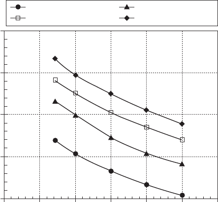
raising the peak cylinder pressure limit. Figure 15.6 shows the impact of
engine displacement and power rating on peak cylinder pressure.
At a given engine speed, there are trade-offs between the air–fuel ratio,
EGR rate, and power rating under a xed constraint of peak cylinder pressure.
Figure 15.7 shows these trade-offs.
Diesel-Xin-15.indd 950 5/5/11 12:07:06 PM
951Diesel engine system specification and subsystem interaction
© Woodhead Publishing Limited, 2011
There is also another fundamental trade-off at a given speed/load between
the peak cylinder pressure and the exhaust manifold gas temperature, both
being design constraints. The trade-off is affected by the shape of the heat
release rate, fuel injection timing, and engine friction. The simulation data
in Fig. 15.8 show the measures needed to bring the cylinder pressure and
exhaust temperature under control at rated power (i.e., moving the curves to
the lower left direction). Reducing the engine compression ratio may reduce
the peak cylinder pressure at the expense of lower indicated thermodynamic
efciency and unaided cold start capability.
The rated power condition is used to dene the compressor and turbine
maximum ow ranges, the cooler size, the maximum heat rejection, the
intake restriction, and the exhaust restriction. In high-EGR engines, usually
the engine delta P at rated power has to be very high due to the small turbine
area sized for the required EGR rate and air–fuel ratio at peak torque. As a
consequence, the EGR valve has to be partially closed in order to prevent
excessive EGR. Therefore, the rated power condition should not be used to
dene the minimum ow restriction of the EGR circuit.
Heavy-duty diesel engine simulation at rated power
with bore-to-stroke ratio 0.8 at fixed high EGR rate
Rated power = 475 hp Rated power = 525 hp
Rated power = 575 hp Rated power = 625 hp
11 12 13 14 15 16 17
Engine displacement (liter)
Peak cylinder gas pressure (psi, absolute)
4500
4000
3500
3000
2500
15.6 Effect of engine displacement and power rating on peak cylinder
pressure.
Diesel-Xin-15.indd 951 5/5/11 12:07:07 PM