Xin Q. Diesel Engine System Design
Подождите немного. Документ загружается.

368 Diesel engine system design
© Woodhead Publishing Limited, 2011
anchor points are connected to form the characteristic curves such as the
gear lines in the engine speed–load domain. Then, at a given vehicle speed,
the vehicle operating point can be visually selected at a preferred gear, and
the corresponding engine speed can be graphically determined. The selected
engine speed is used in the engine speed–load domain to intersect with the
selected gear line. Then the intersection point is the mapped condition of
the running vehicle on the engine map. It should be noted that when the
drivetrain condition changes, the ‘ZWB’ points also change.
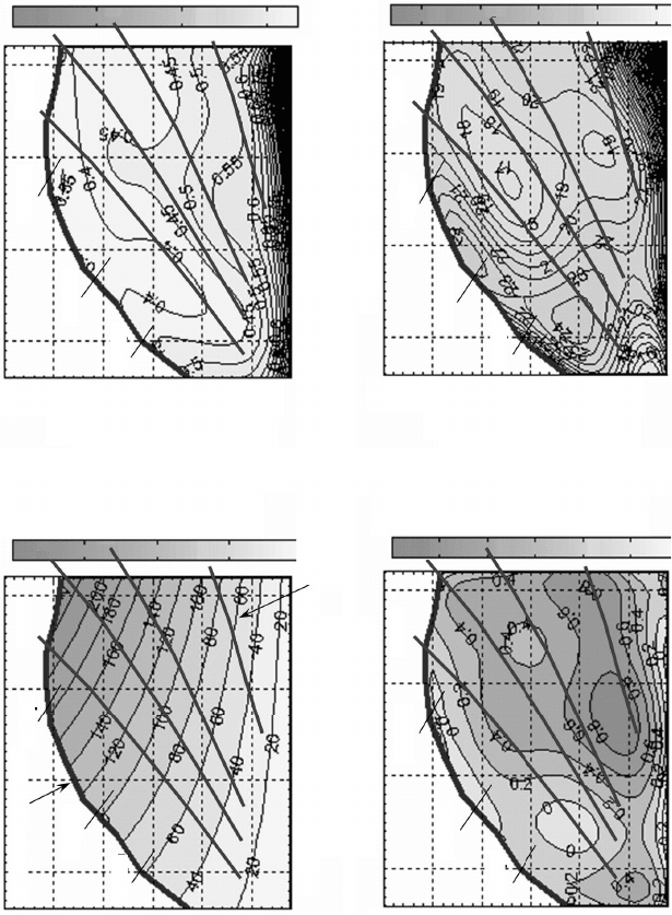
A more powerful matching approach is shown in Fig. 5.9 where the vehicle
speed curves, gear lines and for a selected drivetrain or road condition are
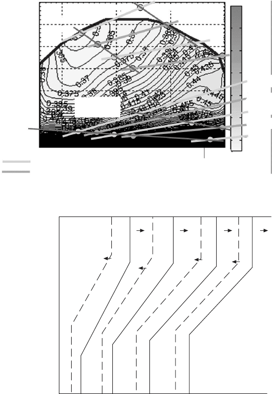
computed and superpositioned on various engine performance maps. Figure
5.10 shows the rear axle lines and road grade lines on the engine BSFC
map. The driving points can be conveniently selected on the engine maps by
considering all the performance characteristics, such as BSFC, air–fuel ratio
smoke limit, power reserve for acceleration, emissions, etc. Moreover, it is
noted that the engine map domain may be viewed as a ‘distorted coordinate’
domain of the transmission shift map (i.e., accelerator pedal position vs.
vehicle speed in Fig. 5.11, compared to Fig. 5.9). Once the transmission shift
schedules are visually located on the engine maps based on all the trade-offs,
the transmission shift map can be directly ‘computed’ with mathematical
coordinate transformation conveniently. Such an analytical method of
engine–transmission matching is more advanced than the traditional ‘trial-
and-error’ approach of generating the transmission shift map.
With this advanced analytical technique of engine–vehicle matching,
drivetrain design parameters and engine–transmission matching can be
evaluated as a part of engine system design. The calculated vehicle operating
characteristics marked on the engine maps provide guidance from vehicle
driving requirements to engine design and testing.
5.3 Powertrain/drivetrain dynamics and transient
performance simulation
5.3.1 Theoretical analysis of transient powertrain
dynamics
Transient powertrain simulation is important for both understanding engine
transient behavior and calculating the cycle-composite fuel economy and
emissions of vehicle driving cycles or engine speed–load certication test
cycles. Taking the time derivative of equation 5.6, the engine acceleration
(i.e., dN
E
/dt) can be obtained as a function of vehicle acceleration (i.e.,
dN
v
/dt) and a time derivative of the transient gear ratio (i.e., di
gr
/dt). In the
derivation below, the transient gear ratio effect is neglected for simplicity.
By substituting equations 5.3, 5.8 and the time derivative of 5.6 into 5.1,
Diesel-Xin-05.indd 368 5/5/11 11:49:21 AM
© Woodhead Publishing Limited, 2011
Engine brake torque
Engine brake torque
Engine brake torque
Engine brake torque
Brake power (hp) BSFC (lb/(hp.hr))
This curve is full pedal
Gear 7
Gear 7 Gear 7
Gear 6
Gear 6
Gear 6
Gear 6
Gear 5
Gear 5
Gear 5
Gear 5
Gear 4
Gear 4 Gear 4
Gear 4
80 mph
80 mph
80 mph
80 mph
63 mph
63 mph
63 mph
63 mph
51 mph
51 mph
51 mph
Engine speed
Brake specific soot (g/(hp.hr)) Air–fuel ratio
Engine speed Engine speed
Engine speed 1 mph = 1.609 km/hr
51 mph
200
150
100
50
0.8
0.6
0.4
0.2
0
–0.2
50
40
30
20
–10
2
1.5
1
0.5
This constant power curve is also
basically constant-vehicle speed curve.
Gear 7
5.9 Engine–vehicle matching method with engine performance characteristic maps.
Diesel-Xin-05.indd 369 5/5/11 11:49:22 AM
370 Diesel engine system design
© Woodhead Publishing Limited, 2011
equation 5.20 is derived as an ordinary differential equation to solve for
the transient engine speed N
E
when a transient engine tractive torque J
E
is
produced (see equation 5.3 on how to relate engine brake torque to vehicle
tractive torque):
Engine brake torque
40 mph
level
ground
RAR = 3.70
RAR = 4.11
Engine speed
Rated speed
40 mph
6% uphill
Note: The curves are first-
order linear approximation.
BSFC (lb/(hp.hr))
60 mph
6% uphill
Gear 6
Gear 5
Gear 6
1
0.9
0.8
0.7
0.6
0.5
0.4
Gear 6 RAR = 3.70
Gear 6 RAR = 4.11
Gear 5 RAR = 3.70
Gear 5 RAR = 4.11
Gear 4
60 mph
level ground
5.10 Engine–vehicle matching for different road grades.
Accelerator pedal position
Full
load
No
load
Vehicle speed
1 2
1 2
2 3
2 3
3 4
4 5
3 4 4 5
5.11 Illustration of transmission shift schedule map.
Gear 5
Diesel-Xin-05.indd 370 5/5/11 11:49:22 AM

371Engine–vehicle matching in diesel powertrain system design
© Woodhead Publishing Limited, 2011
I
N
t
rF
FF
FF
FF
Fm
a
E
E
tir
rF
tir
rF
et
rF
et
rF
er
ac
FF
ac
FF
cb
rr
FF
rr
FF
fa
rrfarr
gl
FF
gl
FF
dr
Fm
dr
Fm
v
d
NdN
d
=
++
FF++FF
FF
er
FF++FF
er
FF
++
FF++FF
cb
++
cb
FF
cb
FF++FF
cb
FF
FF
rr
FF++FF
rr
FF
++
FF++FF
fa
++
fa
FF
fa
FF++FF
fa
FF
+–
Fm+–Fm
Fm
dr
Fm+–Fm
dr
Fm
vvv
dr
iv
e
tir
e
v
gr
tT
vs
tTvstT
lip
I
r
tir
r
tir
a
ii
f
vs
f
vs
–
(
vs
(
vs
1 –
vs
1 –
vs
)
2
Ê
rF
Ê
rF
Ë
rF
Ë
rF
et
Ë
et
rF
et
rF
Ë
rF
et
rF
rF
Á
rF
rF
Ê
rF
Á
rF
Ê
rF
Ë
Á
Ë
rF
Ë
rF
Á
rF
Ë
rF
et
Ë
et
Á
et
Ë
et
rF
et
rF
Ë
rF
et
rF
Á
rF
et
rF
Ë
rF
et
rF
ˆ
¯
˜
ˆ
˜
ˆ
¯
˜
¯
2
ph
gr
ph
gr
ax
ph
ax
ii
ph
ii
gr
ii
gr
ph
gr
ii
gr
h
tT
h
tT
5.20
All the terms in equation 5.20 are in the transient state and can be modeled
in further detail. The tractive force F
t
is produced by engine torque. Transient
engine torque can be modeled in one of the following methods: (1) empirical
formula; (2) model-based formula; (3) mapped engine model; (4) mean-value
cylinder model; or (5) high- delity crank-angle-resolution engine cycle
simulation model. The last two methods may contain a smoke limiter, turbo
lag effect, and transient engine control strategies. Diesel engine transient
torque characteristics are shown in Fig. 5.7. The available transient torque
level depends strongly on how fast the transient event is.
5.3.2 Vehicle driving cycle simulation
In vehicle driving cycle simulations, a vehicle speed schedule as a function
of time is imposed as input, and transient engine torque (or retarding torque
or vehicle braking torque) and engine speed are computed to try to meet the
vehicle speed and load requirements imposed by the vehicle speed schedule
and the gear-shifting schedule, unless the imposed transient change of the
vehicle speed is unrealistic or too fast. Once the engine’s speed and load
state is obtained, fuel consumption and emissions can be calculated either by
using a high- delity engine cycle simulation model or by using the engine
BSFC and emission maps.
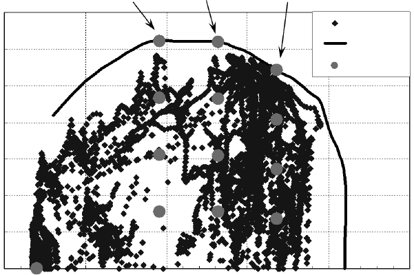
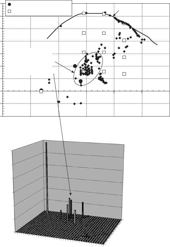
Figure 5.12 shows the US EPA FTP emissions certi cation schedule
mapped on the engine map for a heavy-duty diesel engine. It is observed
that for heavy-duty engine certi cations the high speed and high load
engine operation occupies a major portion of the FTP transient cycle. Figure
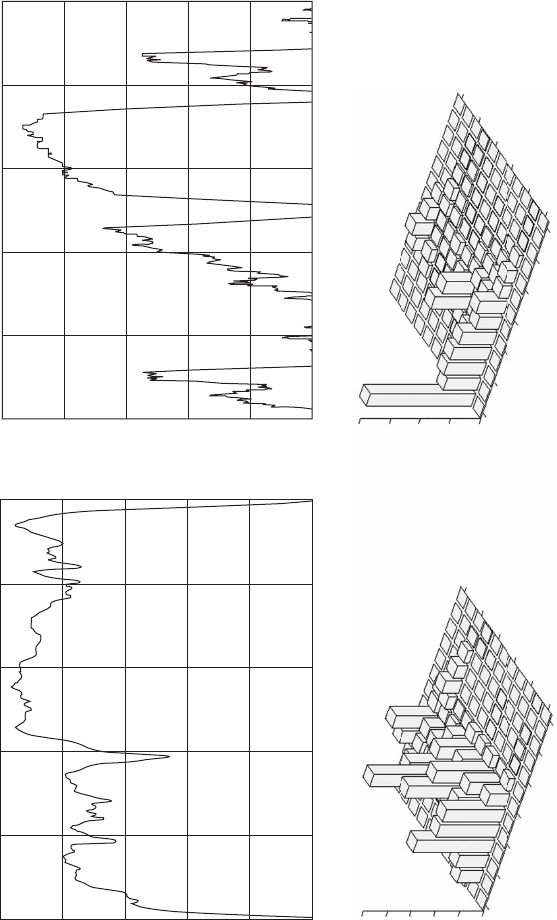
5.13 shows the vehicle speed schedules of the highway fuel economy test
(HWFET) driving cycle and the HD-UDDS driving cycle. Figure 5.13 also
shows the GT-DRIVE simulation results of a heavy-duty Class-8 truck in
these two driving cycles. It is observed that the truck stays much more
time in the region of medium/high loads in the HWFET cycle than in the
lighter duty HD-UDDS cycle. Obviously, the engine design and calibration
strategies for these two different vehicle applications should be optimized
differently. Figure 5.14 illustrates some other commonly used driving cycles
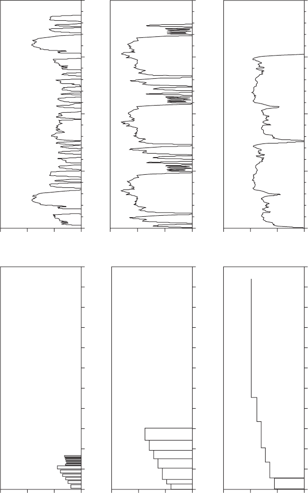
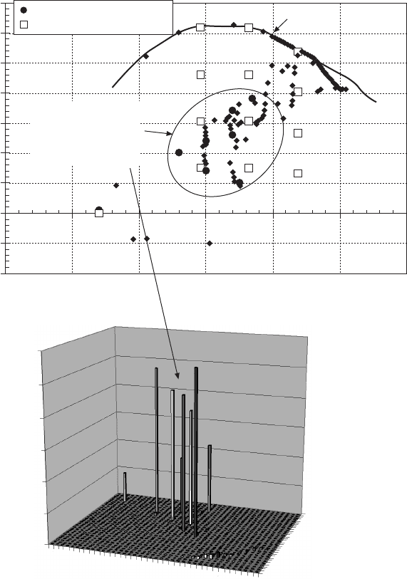
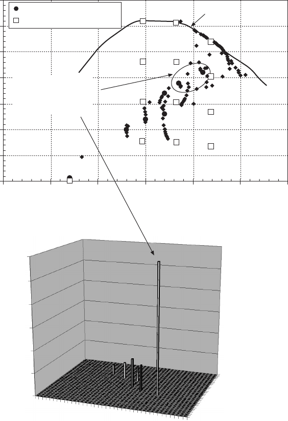
for heavy-duty and light-duty applications. Figures 5.15–5.17 illustrate the
GT-DRIVE simulation results of a medium-duty truck operating in three
different driving cycles: the city route, the suburban route, and the highway
route. It is observed that the city route application gives the lowest engine
load factors, and the highway route demands the engine operate at high speed
Diesel-Xin-05.indd 371 5/5/11 11:49:22 AM
372 Diesel engine system design
© Woodhead Publishing Limited, 2011
and high load for a long period of time. Again, engine design and calibration
should be optimized differently to suit these different applications for this
medium-duty truck. Figure 5.18 shows the driving cycle transient simulation
of a light-duty truck in the engine speed–load domain. It is observed that,
unlike the heavy-duty applications, the light-duty engine mainly operates at
low speeds/loads due to the low vehicle weight. The rated power condition
is only encountered during fast acceleration or high-road-grade operation in
light-duty applications.
5.3.3 Vehicle acceleration simulation
In vehicle full-pedal acceleration simulations, step-fueling and a transmission
gear shift schedule can be imposed as input. Transient engine speed and
vehicle speed can be computed as a function of time.
Figure 5.19 shows a GT-DRIVE simulation of a light-duty truck during
transient full-pedal acceleration from standstill. The rear axle ratio study in
Fig. 5.19 shows that the larger rear axle ratio gives faster vehicle acceleration.
The vehicle weight effect study in Fig. 5.19 illustrates that the vehicle weight
has a paramount impact on acceleration time.
The effect of engine displacement on powertrain transient acceleration is
illustrated in Fig. 5.20. It is observed that in this light-duty truck example
A speed
B speed
C speed
FTP cycle
Lug curve
13 modes
500 1000 1500 2000 2500 3000
Engine speed (rpm)
Engine brake torque (ft.lb)
700
600
500
400
300
200
100
0
5.12 Illustration of SET and FTP operating points on HD diesel engine
speed–load map.
Diesel-Xin-05.indd 372 5/5/11 11:49:23 AM
© Woodhead Publishing Limited, 2011
HWFET cycle
Target Speed
HD-UDDS cycle
Target Speed
Speed (km/hr)
Speed (km/hr)
100
80
60
40
20
0
100
80
60
40
20
0
0 153 306 459 612 765
Time (sec)
0 212 424 636 848 1060
Time (sec)
Time (%)
Time (%)
10
8
6
4
2
0
20
15
10
5
0
Speed (rpm)
Speed (rpm)
Torque (ft.lb)
Torque (ft.lb)
600
600
800
800
1000
1000
1200
1200
1400
1400
1600
1600
1800
1800
1900
1900
1500
1500
1100
1100
700
700
300
300
–100
–100
Percentage of time spent during HWFET cycle Percentage of time spent during HD-UDDS cycle
5.13 Heavy-duty Class-8 truck driving cycle simulation.
Diesel-Xin-05.indd 373 5/5/11 11:49:23 AM
© Woodhead Publishing Limited, 2011
Vehicle speed (km/h)Vehicle speed (km/h)Vehicle speed (km/h)
Vehicle speed (km/h) Vehicle speed (km/h)
Vehicle speed (km/h)
150
100
50
0
150
100
50
0
150
100
50
0
150
100
50
0
150
100
50
0
150
100
50
0
City route
Suburban route
Highway route HWFET
(Note: The cycle is repeated for two times.)
US06
(Note: The cycle is repeated for three times.)
FTP 75
0 1000 2000 3000 4000 5000 6000 7000 8000 9000 10000 11000
Time (second)
0 1000 2000 3000 4000 5000 6000 7000 8000 9000 10000 11000
Time (second)
0 1000 2000 3000 4000 5000 6000 7000 8000 9000 10000 11000
Time (second)
0 500 1000 1500 2000
Time (second)
0 500 1000 1500 2000
Time (second)
0 500 1000 1500 2000
Time (second)
5.14 Illustration of commonly used driving cycles.
Diesel-Xin-05.indd 374 5/5/11 11:49:23 AM
375Engine–vehicle matching in diesel powertrain system design
© Woodhead Publishing Limited, 2011
the 8.3% reduction in engine displacement from 4.8 L to 4.4 L makes a
signicant difference on the vehicle acceleration trajectory mapped in the
engine speed–load domain. The 4.4 L diesel engine takes about 0.3 seconds
longer than the 4.8 L engine to reach 30 mph from standstill (i.e., 3.7 seconds
compared to 3.4 seconds) due to its inferior natural aspiration capability at
the beginning of the acceleration.
Engine brake torque (ft.lb)
700
600
500
400
300
200
100
0
–100
–200
These modes should
be calibrated for
better BSFC by
relaxing emissions
constraints
Engine steady state points
13 mode points
Engine lug curve
Engine speed (rpm)
Time history of engine operating points
0 500 1000 1500 2000 2500 3000
Time spent (sec)
600
500
400
300
200
100
0
700
900
1100
1300
1500
1700
1900
2100
2300
2500
Engine speed (rpm)
80
260
440
620
Engine brake
torque (ft.lb)
5.15 Medium-duty truck driving cycle simulation – city route.
Diesel-Xin-05.indd 375 5/5/11 11:49:24 AM
376 Diesel engine system design
© Woodhead Publishing Limited, 2011
5.3.4 Integrated vehicle–engine driving simulation for
system design
Figure 5.21 demonstrates a simulation capability for a long and slow transient
driving route at high altitude uphill climbing coupled with engine coolant-
induced power derating for a heavy-duty truck. Such a vehicle driving
Engine brake torque (ft.lb)
700
600
500
400
300
200
100
0
–100
–200
These modes should
be calibrated for
better BSFC by
relaxing emissions
constraints
Engine steady state points
13 mode points
Engine lug curve
Engine speed (rpm)
Time history of engine operating points
0 500 1000 1500 2000 2500 3000
Time spent (sec)
600
500
400
300
200
100
0
700
900
1100
1300
1500
1700
1900
2100
2300
2500
Engine speed (rpm)
80
260
440
620
Engine brake
torque (ft.lb)
5.16 Medium-duty truck driving cycle simulation – suburban route.
Diesel-Xin-05.indd 376 5/5/11 11:49:24 AM
377Engine–vehicle matching in diesel powertrain system design
© Woodhead Publishing Limited, 2011
simulation coupled with the engine model is a very valuable tool to assess
the engine derating requirement for coolant heat rejection control. Heavy-
duty trucks usually encounter the most severe condition on the radiator
inlet coolant temperature in high-altitude hot-climate operation due to the
deterioration of the vehicle cooling system with the lower-density cooling
Engine brake torque (ft.lb)
700
600
500
400
300
200
100
0
These modes should
be calibrated for
better BSFC if
possible
Engine steady state points
13 mode points
Engine lug curve
Engine speed (rpm)
Time history of engine operating points
0 500 1000 1500 2000 2500 3000
Time spent (sec)
6000
5000
4000
3000
2000
1000
0
700
900
1100
1300
1500
1700
1900
2100
2300
2500
Engine speed (rpm)
80
260
440
620
Engine brake
torque (ft.lb)
5.17 Medium-duty truck driving cycle simulation – highway route.
Diesel-Xin-05.indd 377 5/5/11 11:49:25 AM