Xin Q. Diesel Engine System Design
Подождите немного. Документ загружается.


328 Diesel engine system design
© Woodhead Publishing Limited, 2011
the turbine physical area, which is a constant related to the nozzle throat
area and the exducer throat area; and the turbine ow coef cient, which is
a variable as a function of turbine pressure ratio and turbine speed.
In equations 4.39–4.56, the parameters of gas pressure, temperature, and
ow rate can be either cycle-average steady-state values or instantaneous
quantities as a function of crank angle in a quasi steady-state. The earlier
equation 4.7 in a transient differential form is essentially the same as the
steady-state form equation 4.39 in nature. They are both based on the energy
conservation that can solve for T
3
. The earlier equation 4.10 is essentially
the same as 4.40 in nature. They are both based on the mass conservation
that can solve for
m
ai
r
. It is worth noting that the steady-state cycle-average
integral of the in-cylinder pressure is essentially the engine power, re ected
by equation 4.38. In the formulation of equations 4.39–4.56, the engine brake
power is assumed to be a known input value. If the power is an unknown,
the governing equation 4.12 of the in-cylinder instantaneous cycle process
must be used to solve for the in-cylinder pressure, and then its steady-state
counterpart equation 4.38 must be used to integrate over an engine cycle in
order to solve for the brake power.
Because equations 4.51–4.52 are included to describe particular
characteristics of the turbo hardware, the formulation of 4.39–4.56 can only
be used to predict the engine performance of given hardware. Equations
4.39–4.56 consist of a nonlinear system that has to be solved iteratively
by assuming an initial value for one of the 18 unknowns and iterating to
convergence.
4.4.2 Hardware specifi cation design for target
performance
In the previous section, predicting hardware performance was discussed. In
fact, in engine air system speci cation design, the objective is to nd the
required hardware (e.g., turbine effective area) to match with a given functional
target of engine air ow rate (or gravimetric air–fuel ratio) and EGR rate.
Recall that the EGR rate here is de ned as the ratio between the EGR mass
ow rate and the total mass ow rate of EGR and fresh air. If the desirable
compressor and turbine ef ciencies are assumed as xed input, a system of
16 equations (4.39–4.48 and 4.51–4.56) is formed. The 16 unknowns are
m
ai
r
,
m
EG
R
EGREG
, T
3
, p
4
, T
1,ROA
, p
1
, p
2
, T
2
, p
3
, T
4
, N
C
, N
T
, p
2a
, T
2a
, T
CACout
,
and
T
EGRcoolerGasOut
. The turbine speed can still be guaranteed to be equal to the
compressor speed because equations 4.48, 4.51, and 4.52 are used. However,
the turbocharger speed is usually not required in the output of engine system
speci cation calculations. Instead, the turbine area is a required speci cation
design parameter. Therefore, by deleting the turbocharger speed and the
turbocharger map equations 4.48–4.52 that describe xed turbo hardware
Diesel-Xin-04.indd 328 5/5/11 11:47:40 AM

329Fundamentals of dynamic and static engine system designs
© Woodhead Publishing Limited, 2011
characteristics, and by adding equation 4.57, a mathematical system of
14 equations (4.39–4.47 and 4.53–4.57) can be formed for engine system
speci cation design. In fact, this system can be used for two purposes: (1)
to calculate the required hardware for a given performance target; or (2) to
calculate the performance for a given hardware con guration, although in a
simpli ed form of 4.39–4.56. For example, the 14 unknowns can be
m
ai
r
or
A
T
,
m
EG
R
EGREG
, T
3
, p
4
, T
1,ROA
, p
1
, p
2
, T
2
, p
3
, T
4
, p
2a
, T
2a
, T
CACout
, T
EGRcoolerGasOut
and it should be noted that this set of 14 equations can be reformulated to any
smaller sets if the number of unknowns is reduced accordingly. In engine air
system design, it is important to understand the engineering implications behind
this mathematical formulation. When
m
ai
r
is known and A
T
is unknown, the
required turbine area needs to be found to match the given air ow rate. In
such a calculation without using turbocharger speed maps and turbocharger
ef ciency maps, the calculation does not guarantee that the turbine speed is
equal to the compressor speed, although it still calculates the ow rate and
the pressure ratio of the compressor and the turbine.
In system speci cation design analysis, in order to achieve the minimum
engine delta P at a xed target of air–fuel ratio and EGR rate, it is often
convenient and necessary for the engine manufacturer to start by computing
the required turbocharger ef ciency and propose the desired turbocharger
speci cation (i.e., turbocharger ow rate, pressure ratio, and a ‘ xed’
required ef ciency) to the turbocharger suppliers. It should be noted that
the assumption of imposed turbocharger ef ciency sometimes might not be
realistic for real turbocharger hardware, especially when the xed ef ciencies
are speci ed at multiple engine speed and load modes. The turbocharger
suppliers have the responsibility to select or design turbochargers to reach
the ef ciency requirements speci ed by the engine manufacturer. They are
also responsible for matching a turbocharger with a proper rotating shaft
speed to reach the desired ow rate and pressure ratio speci ed by the
engine manufacturer as closely as possible. After obtaining the proposed
turbocharger maps from the suppliers, the engine manufacturer can check
turbocharger hardware performance with computer simulations (i.e., using
the formulation of equations 4.39–4.56). The performance gap between the
proposed turbocharger hardware and the system design speci cation can
then be identi ed.
4.4.3 The characteristics of engine delta P
Engine delta P is a critical part of pumping loss. There are four core equations
related to engine air system performance: equation 4.40 for engine–turbocharger
coupled breathing characteristic, equation 4.44 for EGR circuit ow restriction,
equation 4.47 for linking the intake manifold boost pressure to the exhaust
manifold pressure, and equation 4.57 (or its equivalent counterpart of radial
Diesel-Xin-04.indd 329 5/5/11 11:47:40 AM
330 Diesel engine system design
© Woodhead Publishing Limited, 2011
ow turbines) for generating the engine air ow by the turbine. Substituting
4.40 into 4.47, the parametric dependency of engine delta P (p
3
– p
2a
) can
be re ected by 4.47 and 4.57. With the engine air ow rate and the EGR
rate as known target inputs (or equivalently the intake manifold pressure
p
2a
and the EGR rate as known targets by using 4.40), when T
3
and p
4
are
constant, if the turbine area A
T
varies, the exhaust manifold pressure p
3
changes according to 4.57. Thus, a change in p
2
,
hh
h
CT
hh
CT
hh
h
CT
h
TC
m
ech
TC
,
()
TC
()
TC
mm()mm
TC
mm
TC
()
TC
mm
TC
()
TT()TT
()
()
()
//
()//()
TC
()
TC
//
TC
()
TC
mm()mm//mm()mm
TC
mm
TC
()
TC
mm
TC
//
TC
mm
TC
()
TC
mm
TC
()//()
TT()TT//TT()TT
()
()//()
()
31
()
31
()
TT()TT
31
TT()TT
()//()
31
()//()
TT()TT//TT()TT
31
TT()TT//TT()TT
or p
4
is required in order to balance the equation in 4.47. Therefore, the
parameters that can reduce the engine delta P (i.e., minimize p
3
at a given
p
2a
) are shown directly in 4.47 and 4.57. These parameters are: p
1
, p
2
, the
term
hh
h
CT
hh
CT
hh
h
CT
h
TC
ech
TT
,3
m,3m
ech,3ech
TC,3TC
1
TT
1
TT
()
mm()mm
,3
()
,3
TC,3TC
()
TC,3TC
mm
,3
mm()mm
,3
mm
TC
mm
TC,3TC
mm
TC
()
TC
mm
TC,3TC
mm
TC
(/
TT(/TT
,3
(/
,3
TT
,3
TT(/TT
,3
TT
)
()
()
()/()
mm()mm/mm()mm
TC,3TC
()
TC,3TC
/
TC,3TC
()
TC,3TC
mm
,3
mm()mm
,3
mm/mm
,3
mm()mm
,3
mm
TC
mm
TC,3TC
mm
TC
()
TC
mm
TC,3TC
mm
TC
/
TC
mm
TC,3TC
mm
TC
()
TC
mm
TC,3TC
mm
TC
()
()/()
()
, p
4
, and A
T
. Note that the compressor
inlet temperature T
1
is affected by ROA. The compressor inlet pressure
p
1
is affected by the degree of ow throttling at the compressor inlet. The
compressor outlet pressure p
2
is affected by engine speed, volumetric ef ciency
(especially valve timing), effective engine displacement and intake manifold
temperature, as shown in equation 4.40. The pressure p
2
is also affected by
charge air cooler ow restriction and intake throttle as shown in equation
4.56. The turbine inlet temperature T
3
is affected by cylinder cooling and
heat losses from the exhaust port and the exhaust manifold, as shown in
equation 4.39. T
3
is also affected by the air–fuel ratio. The turbine ow rate
m
T
is affected by turbine wastegate opening. The turbine outlet pressure p
4
is affected by aftertreatment exhaust restriction C
d,exh
as shown in equation
4.43. The turbocharger ef ciency h
C
h
T
h
TC,mech
and the turbine area A
T
are
turbocharger design parameters.
EGR circuit ow restriction also affects engine delta P and other system
design parameters. In a HPL EGR system, the EGR circuit ow restriction
coef cient C
d,EGR
(or lumped EGR valve opening) can be solved using
equation 4.44 when p
3
– p
2a
and the EGR ow rate are known. On the other
hand, at a xed air ow rate and EGR rate (or equivalently, at a xed EGR
mass ow rate), when the EGR circuit ow restriction is also xed, p
3
must
be calculated using equation 4.44. Then the turbine area A
T
needs to change
according to equation 4.57, and simultaneously another change is required
in one of the following in order to balance equation 4.47: p
1
, p
2
, the term
hh
h
CT
hh
CT
hh
h
CT
h
TC
m
ech
TC
,
TC,TC
//
()
TC
()
TC
mm()mm
TC
mm
TC
()
TC
mm
TC
//()//
TC
//
TC
()
TC
//
TC
mm//mm()mm//mm
TC
mm
TC
//
TC
mm
TC
()
TC
mm
TC
//
TC
mm
TC
()
TT()TT
//()//
TT//TT()TT//TT
()
()
//()//
//()//
31
()
31
()
TT()TT
31
TT()TT
//()//
31
//()//
TT//TT()TT//TT
31
TT//TT()TT//TT
, or p
4
.
Using the model of exhaust manifold gas temperature as shown in equation
14.4 in Chapter 14, the factors affecting the cycle-average engine delta P
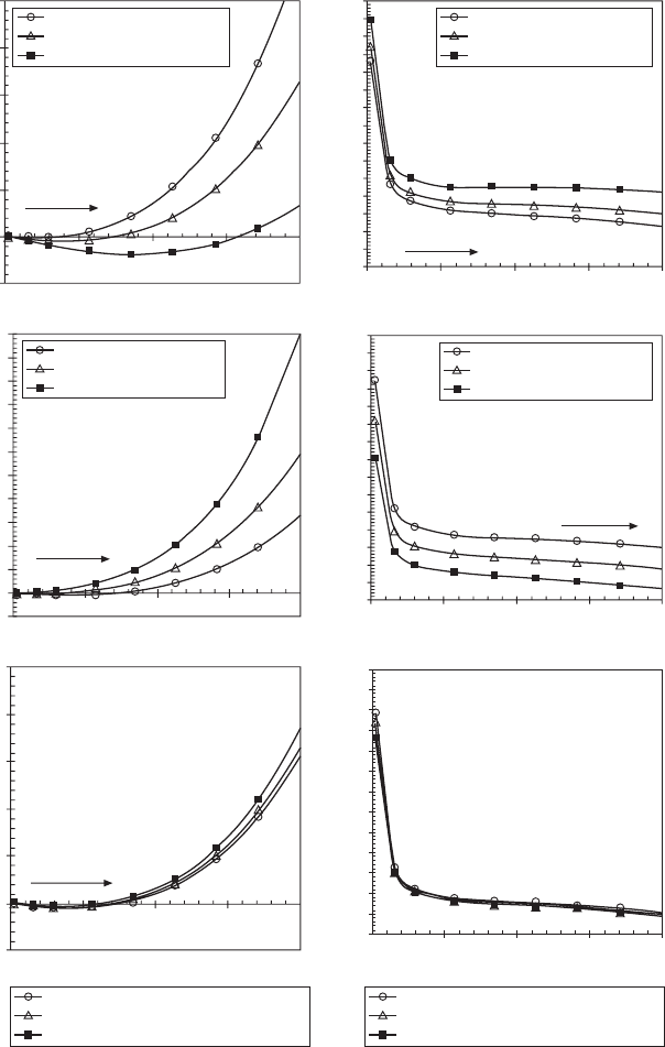
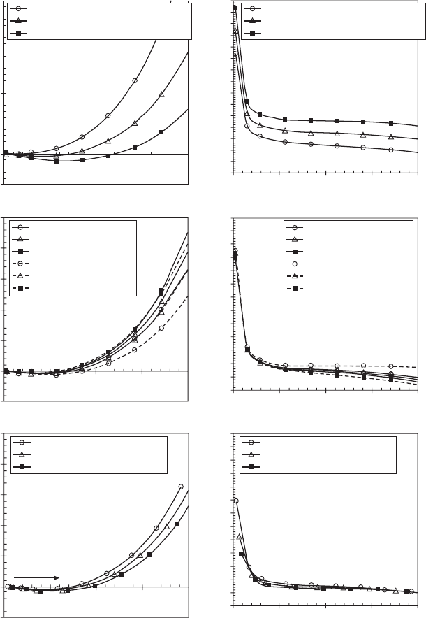
are obtained by solving equations 4.40, 4.47, and 4.57. Figure 4.5 illustrates
that the following design may reduce engine delta P at a given speed–load
mode and xed targets of air–fuel ratio and EGR rate: higher turbocharger
ef ciency, higher exhaust manifold gas temperature, less turbine wastegating,
lower exhaust restriction pressure drop, and lower charge air cooler pressure
drop. It is also observed that at higher engine load (fueling rate), engine delta
P becomes higher. It is worth noting that in some engine designs with reed
Diesel-Xin-04.indd 330 5/5/11 11:47:41 AM
331Fundamentals of dynamic and static engine system designs
© Woodhead Publishing Limited, 2011
Engine delta P (bar)
Engine delta P (bar)
Engine delta P (bar)
Turbine effective area (cm
2
)
Turbine effective area (cm
2
)
Turbine effective area (cm
2
)
5
4
3
2
1
0
–1
5
4
3
2
1
0
–1
11
10
9
8
7
6
5
4
3
2
1
0
–1
18
17
16
15
14
13
12
11
10
9
8
7
6
5
4
3
18
17
16
15
14
13
12
11
10
9
8
7
6
5
4
3
18
17
16
15
14
13
12
11
10
9
8
7
6
5
1 2 3 4 5
1 2 3 4 5
1 2 3 4 5
1 2 3 4 5
1 2 3 4 5
1 2 3 4 5
Intake manifold boost pressure (bar
absolute)
Intake manifold boost pressure (bar
absolute)
Intake manifold boost pressure (bar
absolute)
Intake manifold boost pressure (bar
absolute)
Intake manifold boost pressure (bar
absolute)
Intake manifold boost pressure (bar
absolute)
Turbocharger efficiency 45%
Turbocharger efficiency 50%
Turbocharger efficiency 60%
Turbine wastegated 0%
Turbine wastegated 10%
Turbine wastegated 20%
CAC or intake throttle pressure drop 2≤Hg
CAC or intake throttle pressure drop 4≤Hg
CAC or intake throttle pressure drop 8≤Hg
CAC or intake throttle pressure drop 2≤Hg
CAC or intake throttle pressure drop 4≤Hg
CAC or intake throttle pressure drop 8≤Hg
Turbine wastegated 0%
Turbine wastegated 10%
Turbine wastegated 20%
Turbocharger efficiency 45%
Turbocharger efficiency 50%
Turbocharger efficiency 60%
Assumptions:
2000 rpm, T
1
= 298K
A/F = 23, EGR = 30%
No wastegating
Volumetric efficiency 90%
Assumptions:
2000 rpm, T
1
= 298K
A/F = 23, EGR = 30%
Turbo efficiency 50%
Assumptions:
2000 rpm, T
1
= 298K
A/F = 23, EGR = 30%
Turbo efficiency 50%
No wastegating
Assumptions:
2000 rpm, T
1
= 298K
A/F = 23, EGR = 30%
Turbo efficiency 50%
No wastegating
Assumptions:
2000 rpm, T
1
= 298K
A/F = 23, EGR = 30%
Turbo efficiency 50%
Assumptions:
2000 rpm, T
1
= 298K
A/F = 23, EGR = 30%
No wastegating
Fuel rate increases from
40 to 180 mg/stroke
Fuel rate increases from
40 to 180 mg/stroke
Fuel rate increases from
40 to 180 mg/stroke
Fuel rate increases
Fuel rate increases
4.5 Theoretical analysis of engine delta P.
Diesel-Xin-04.indd 331 5/5/11 11:47:41 AM
332 Diesel engine system design
© Woodhead Publishing Limited, 2011
Engine delta P (bar)
Engine delta P (bar) Engine delta P (bar)
Turbine effective area (cm
2
)
Turbine effective area (cm
2
)
Turbine effective area (cm
2
)
5
4
3
2
1
0
–1
5
4
3
2
1
0
–1
5
4
3
2
1
0
–1
18
17
16
15
14
13
12
11
10
9
8
7
6
5
4
3
18
17
16
15
14
13
12
11
10
9
8
7
6
5
18
17
16
15
14
13
12
11
10
9
8
7
6
5
1 2 3 4 5
1 2 3 4 5
1 2 3 4 5
1 2 3 4 5
1 2 3 4 5
1 2 3 4 5
Intake manifold boost pressure (bar
absolute)
Intake manifold boost pressure (bar
absolute)
Intake manifold boost pressure (bar
absolute)
Intake manifold boost pressure (bar
absolute)
Intake manifold boost pressure (bar
absolute)
Intake manifold boost pressure (bar
absolute)
Turbine inlet temperature lower by 100K
Turbine inlet temperature baseline
Turbine inlet temperature higher by 100K
Turbine inlet temperature lower by 100K
Turbine inlet temperature baseline
Turbine inlet temperature higher by 100K
Intake restriction 1≤Hg
Intake restriction 2≤Hg
Intake restriction 3≤Hg
Exhaust restriction 4≤Hg
Exhaust restriction 8≤Hg
Exhaust restriction 12≤Hg
Intake restriction 1≤Hg
Intake restriction 2≤Hg
Intake restriction 3≤Hg
Exhaust restriction 4≤Hg
Exhaust restriction 8≤Hg
Exhaust restriction 12≤Hg
Intake manifold temperature 13°F
Intake manifold temperature 16°F
Intake manifold temperature 19°F
Intake manifold temperature 13°F
Intake manifold temperature 16°F
Intake manifold temperature 19°F
Assumptions:
2000 rpm, T
1
= 298K
A/F = 23, EGR = 30%
Turbo efficiency 50%
No wastegating
Assumptions:
2000 rpm, T
1
= 298K
A/F = 23, EGR = 30%
Turbo efficiency 50%
No wastegating
Assumptions:
2000 rpm, T
1
= 298K
A/F = 23, EGR = 30%
Turbo efficiency 50%
No wastegating
Assumptions:
2000 rpm, T
1
= 298K
A/F = 23, EGR = 30%
Turbo efficiency 50%
No wastegating
Assumptions:
2000 rpm, T
1
= 298K
A/F = 23, EGR = 30%
Turbo efficiency 50%
No wastegating
Assumptions:
2000 rpm, T
1
= 298K
A/F = 23, EGR = 30%
Turbo efficiency 50%
No wastegating
Fuel rate increases from
40 to 180 mg/stroke
4.5 Continued
valves (check valves), EGR ow can be harvested into the cylinder with
the pulsating pressure differential even if the cycle-average engine delta P
becomes slightly negative.
Diesel-Xin-04.indd 332 5/5/11 11:47:42 AM
333Fundamentals of dynamic and static engine system designs
© Woodhead Publishing Limited, 2011
The effect of turbine wastegating can be explained as follows. With
wastegating the turbine ow loss must be compensated by an increase in the
turbine pressure ratio in order to maintain a sufcient turbine power in order
to deliver a target compressor boost pressure. The larger turbine pressure
ratio results in an inevitable increase in both the exhaust manifold pressure
and the engine delta P. Variable geometry turbine (VGT) does not have
wastegate ow losses, hence it may produce lower pumping loss and BSFC
than a wastegated turbine, provided both turbines have a similar efciency.
It should be noted that in some two-stage turbochargers, there is usually a
high-pressure-stage turbine bypass valve or wastegate to divert the exhaust
ow to the low-pressure-stage turbine inlet. The bypassed exhaust ow in
a two-stage turbocharger is not all wasted because it is utilized by the low-
pressure-stage turbine to deliver certain boost. But some ow throttling loss
does occur at the wastegate when the valve is partially open.
In EGR engine design, insufcient engine delta P and inadequate capability
to drive EGR ow often occur at low engine speeds, especially at the
peak torque condition. In a turbocharged engine, the turbine effective area
delivers and controls the exhaust manifold pressure and the compressor boost
pressure. It acts as a restricting orice and also a power-producing element
to drive the compressor. The required turbine area can be determined using
equation 4.57. It is the turbine area that primarily decides the engine delta
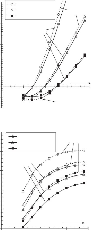
P relationships described above. With a xed turbine area, engine delta P
reduces as the engine speed decreases at a xed load, as shown in Fig. 4.6.
The gure is obtained by using the four core equations (4.40, 4.44, 4.47,
and 4.57). It is observed that a smaller turbine area produces higher engine
delta P to enable EGR driving at low speeds. Figure 4.6 also shows that at a
xed target air–fuel ratio at a low speed, turbocharger efciency should not
be too high because otherwise the large turbine area would have produced
very low or even negative engine delta P that cannot drive EGR ow (EGR
rate 30% in Fig. 4.6).
4.4.4 Summary of theoretical options of engine air
system design
From the set of 14 equations used for engine system specication design
(4.39–4.47 and 4.53–4.57), any 14 parameters can be chosen as unknowns
to formulate the equation system in order to evaluate the effects of engine
hardware design or operating conditions. Sixteen typical air systems are listed
in Table 4.1 to cover most air system design possibilities with HPL EGR. In
Table 4.1 the second column lists possible unknowns, either a performance
parameter or a hardware design parameter. One unknown needs to be chosen
from each equation in order to formulate an air system. The parameters listed
under each system number are the 14 unknowns. The parameters not shown
Diesel-Xin-04.indd 333 5/5/11 11:47:42 AM
334 Diesel engine system design
© Woodhead Publishing Limited, 2011
under each system number but shown in the second column are assumed
as known input data. The hardware or calibration parameters are shown
as bold in Table 4.1. For example, in system 1, h
C
(compressor efciency),
Turbine area 5 cm
2
Turbine area 6 cm
2
Turbine area 7 cm
2
Turbo
efficiency 50%
Turbo
efficiency 60%
Assumptions:
(1) Constant fuel
rate 180 mg/cycle
(2) T
3
changes as
a function of A/F
ratio
(3) Volumetric
efficiency 90%
Turbine flow
rate increases
Cannot drive EGR
Engine speed (rpm)
500 1000 1500 2000 2500
Engine delta P (bar)
8
7
6
5
4
3
2
1
0
–1
–2
Turbine area 5 cm
2
Turbine area 6 cm
2
Turbine area 7 cm
2
Turbo
efficiency 60%
Turbo
efficiency 50%
Turbine flow
rate increases
500 1000 1500 2000 2500
Engine speed (rpm)
A/F ratio
35
30
25
20
15
10
4.6 The effect of engine speed on engine delta P.
Diesel-Xin-04.indd 334 5/5/11 11:47:42 AM

© Woodhead Publishing Limited, 2011
Table 4.1 Mathematical formulation of HPL EGR engine air systems at given engine speed, fueling rate, and power
Engine system number
Eq.
no.
Possible
unknowns
1 2 3 4 5 6 7 8 9 10 11 12 13 14 15 16
4.39 T
3
, Q
base-coolant
T
3
T
3
T
3
T
3
T
3
T
3
T
3
T
3
T
3
T
3
T
3
T
3
T
3
T
3
T
3
T
3
4.40 h
vol
, m˙
air
,
m˙
EGR
, T
2a
, p
2a
,
V
E
m˙
air
p
2a
p
2a
p
2a
p
2a
p
2a
p
2a
p
2a
p
2a
p
2a
p
2a
p
2a
p
2a
p
2a
p
2a
T
2a
4.41 m˙
air
, C
d,int
, p
1
,
p
ambient
p
1
p
1
p
1
p
1
p
1
p
1
p
1
p
1
p
1
p
1
p
1
p
1
p
1
p
1
p
1
p
1
4.42 T
1,ROA
, DT
ROA
,
T
ambient
T
1,ROA
T
1,ROA
T
1,ROA
T
1,ROA
T
1,ROA
T
1,ROA
T
1,ROA
T
1,ROA
T
1,ROA
T
1,ROA
T
1,ROA
T
1,ROA
T
1,ROA
T
1,ROA
T
1,ROA
T
1,ROA
4.43 C
d,exh
, p
4
,
p
ambient
p
4
p
4
p
4
C
d,exh
p
4
p
4
p
4
C
d,exh
p
4
p
4
C
d,exh
p
4
p
4
C
d,exh
C
d,exh
p
4
4.44 m˙
EGR
, C
d,EGR
,
p
3
, p
2a
m˙
EGR
C
d,EGR
C
d,EGR
C
d,EGR
C
d,EGR
C
d,EGR
p
3
p
3
p
3
p
3
p
3
p
3
p
3
p
3
p
3
p
2a
4.45 h
C
, p
1
, p
2
, T
1
,
T
2
T
2
T
2
T
2
T
2
T
2
T
2
T
2
T
2
T
2
T
2
T
2
T
2
T
2
T
2
T
2
p
2
4.46 h
T
, p
3
, p
4
, T
3
,
T
4
T
4
T
4
T
4
T
4
T
4
T
4
T
4
T
4
T
4
T
4
T
4
T
4
T
4
T
4
T
4
T
4
4.47 p
1
, p
2
, h
C
, h
T
,
h
TC,mech
, m˙
T
,
T
1
, T
3
, p
3
, p
4
p
2
p
3
p
3
p
4
p
2
h
T/C
m˙
T
p
4
p
2
h
T/C
p
4
p
2
h
T/C
p
2
h
T/C
h
T/C
4.53a m˙
air
, m˙
EGR
,
T
CACout
,,
T
EGRcoolerGasOut
,
T
2a
T
2a
T
2a
T
2a
T
2a
T
2a
T
2a
T
2a
T
2a
T
2a
T
2a
T
2a
T
2a
T
2a
T
2a
T
2a
T
CACout
Diesel-Xin-04.indd 335 5/5/11 11:47:42 AM

© Woodhead Publishing Limited, 2011
4.54 E
CAC
, T
2
,
T
CACout
T
CACout
T
CACout
T
CACout
T
CACout
T
CACout
T
CACout
T
CACout
T
CACout
T
CACout
T
CACout
T
CACout
T
CACout
T
CACout
T
CACout
T
CACout
T
2
4.55 e
EGRcooler
, T
3
,
T
EGRcoolerGasOut
(= T
EGR
)
T
EGR
T
EGR
T
EGR
T
EGR
T
EGR
T
EGR
T
EGR
T
EGR
T
EGR
T
EGR
T
EGR
T
EGR
T
EGR
T
EGR
T
EGR
T
EGR
4.56 m˙
air
, p
2
, p
2a
,
C
d,CAC-IT
(= C
d,IT
)
p
2a
p
2
p
2
p
2
C
d,IT
p
2
p
2
p
2
C
d,IT
p
2
p
2
C
d,IT
p
2
C
d,IT
p
2
C
d,IT
4.57 m˙
T
, A
T
, T
3
,
p
3
, p
4
p
3
A
T
m˙
T
p
3
p
3
p
3
A
T
A
T
A
T
A
T
m˙
T
m˙
T
m˙
T
p
4
p
4
p
3
Engine system number
Eq.
no.
Possible
unknowns
1 2 3 4 5 6 7 8 9 10 11 12 13 14 15 16
Table 4.1 Continued
Diesel-Xin-04.indd 336 5/5/11 11:47:43 AM
337Fundamentals of dynamic and static engine system designs
© Woodhead Publishing Limited, 2011
C
d,EGR
(EGR valve opening), A
T
(turbine effective area) and
m
T
(turbine
ow rate, essentially representing turbine wastegate opening) are assumed
to be known xed hardware or calibration parameters. System 1 solves 14
performance parameters as unknowns with a given set of hardware and
calibration. For a xed pair of air–fuel ratio and EGR rate target, each of
systems 2–16 needs to be solved for two hardware or calibration parameters.
The two hardware selections have a certain exibility of regulating the
air–fuel ratio and the EGR rate within a range. Different systems of hardware
formulation provide a different range of controllability. Systems 2–6 have
high pumping loss when the EGR circuit ow coef cient C
d,EGR
is low (i.e.,
more restrictive). Systems 7–9, 11 and 12 are practical ones with a known
turbocharger ef ciency and a known maximum C
d,EGR
. They can be used to
seek hardware to reach a target air–fuel ratio and EGR rate with the minimum
engine delta P (p
3
– p
2a
). Systems 10 and 13 can be used to compute the
required turbocharger ef ciency, turbine area or wastegate opening with a
given exhaust restriction ow coef cient C
d,exh
in order to achieve a target
air–fuel ratio and EGR rate. System 14 may have some redundancy in
functionality because the exhaust back pressure valve and the intake throttle
valve have similar or related effects on engine performance. System 15 (or
16) can be used to compute the required turbocharger ef ciency and exhaust
(or intake) restriction with a given turbine. The mathematical formulations of
LPL EGR and hybrid EGR systems can be derived similarly. In LPL EGR,
although intake air throttling at the compressor inlet may be used to induct
EGR ow, it is usually less effective than using an exhaust back pressure
valve at the turbine outlet. It is worth noting that the non-EGR engine can
be viewed as a simpli ed form of the above system formulation. The engine
applications of Table 4.1 will be elaborated in Chapter 13.
4.5 Steady-state model tuning in engine cycle
simulation
In engine cycle simulation, tuning the model is one of the most dif cult tasks
in EPSI analysis because of the complex interactions among the performance
parameters of different subsystems. Model tuning refers to calibrating the
model to adjust the hardware features to match known engine test data. The
key to building a successful model is to identify and tune appropriate model
parameters to re ect the true physics governing the engine performance test
data. The theoretical foundation of model tuning can be found in Section 4.4.2.
Those equations capture many hardware design parameters that can easily
be tuned in the model (e.g., turbine area and ef ciency). However, there are
more complex physical processes that cannot be modeled very accurately by
the zero-dimensional or one-dimensional engine cycle simulation software,
such as the in-cylinder combustion, BSFC, and heat transfer. It should be
Diesel-Xin-04.indd 337 5/5/11 11:47:43 AM
