Werner Leonhard Control of Electrical Drives
Подождите немного. Документ загружается.

320 13.
Induction
Motor
Drive
with
Reduced
Speed
Range
y (v+
1)
e-
jWot
PWM
sector
.Y
Ref e-j wot
y(v-l)
e- jwot
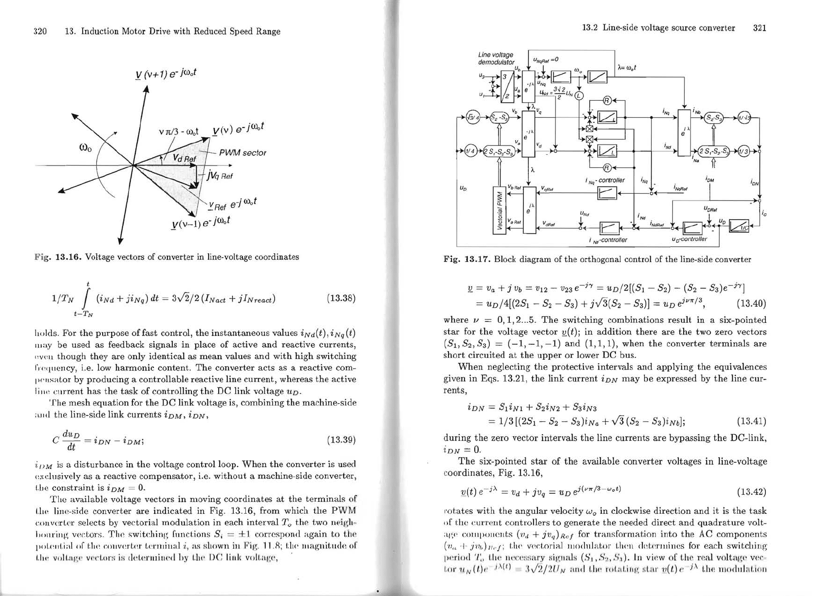
Fi
g.
13.16.
Volt age vectors of
converter
in
line-voltage
coordinates
t
l/lN
I
(iNd
+ jiNq) dt =
3.J2/2
(INact + jINreacd
(13.38)
t-T
N
holds. For
the
purpose
offast
control,
the
instantaneous values iNd(t), iNq (t)
llIay
be used as feedback signals
in
place of active
and
reactive currents,
"VI'H
though
they
are only identical as
mean
values and with high switching
fJ'c<[llcncy,
i.e. low harmonic contento
The
converter
acts
as a reactive com-
1)(
'
llsator
by producing a controllable reactive line current, whereas
the
active
I iII\: c
mrent
has
the
task
of controlling
the
DC link volt age
UD.
The
mesh equation for
the
DC link volt age is, combining
the
ma
chine-side
;\.lId
the line-side link currents iDM, iDN,
dUD.
.
C
~-
= tDN -
tDM;
(13.39)
dt
·i
/)
M
is
a disturbance in
the
voltage
controlloop.
When
the
converter is used
(!xdusivelyas a reactive compensator, i.e.
without
a machine-side converter,
I.be
constraint
is
iDM
=
O.
The
available voltage vectors
in
moving coordinates
at
the
terminaIs
of
1.11('
line-side converter are indicated in Fig. 13.16, from which
the
PWM
collvcrlcr selects by vectorial modulation in each
intervall
'o
the
two
neigh
~
"O\lriIl~\
vec.tors.
Th
e switching fllIlctions Si
==
±1 correspond again
to
ti\('
!'ol.(:II(.ial
nf
(;11(
: (".()\lvcr!;(!r
lel"llliual
i, as Hl1oWI\
ill
Fig.
11.R; t:lw Jlla
gnitlldc
01'
1,111'
voll
,
iI,/'
,
('
V('('!.!)!":;
i:;
dd.<
!
rlllill('d
hy
LI\('
1>(;
lilll(
VO]l.i
\l
!
;<',
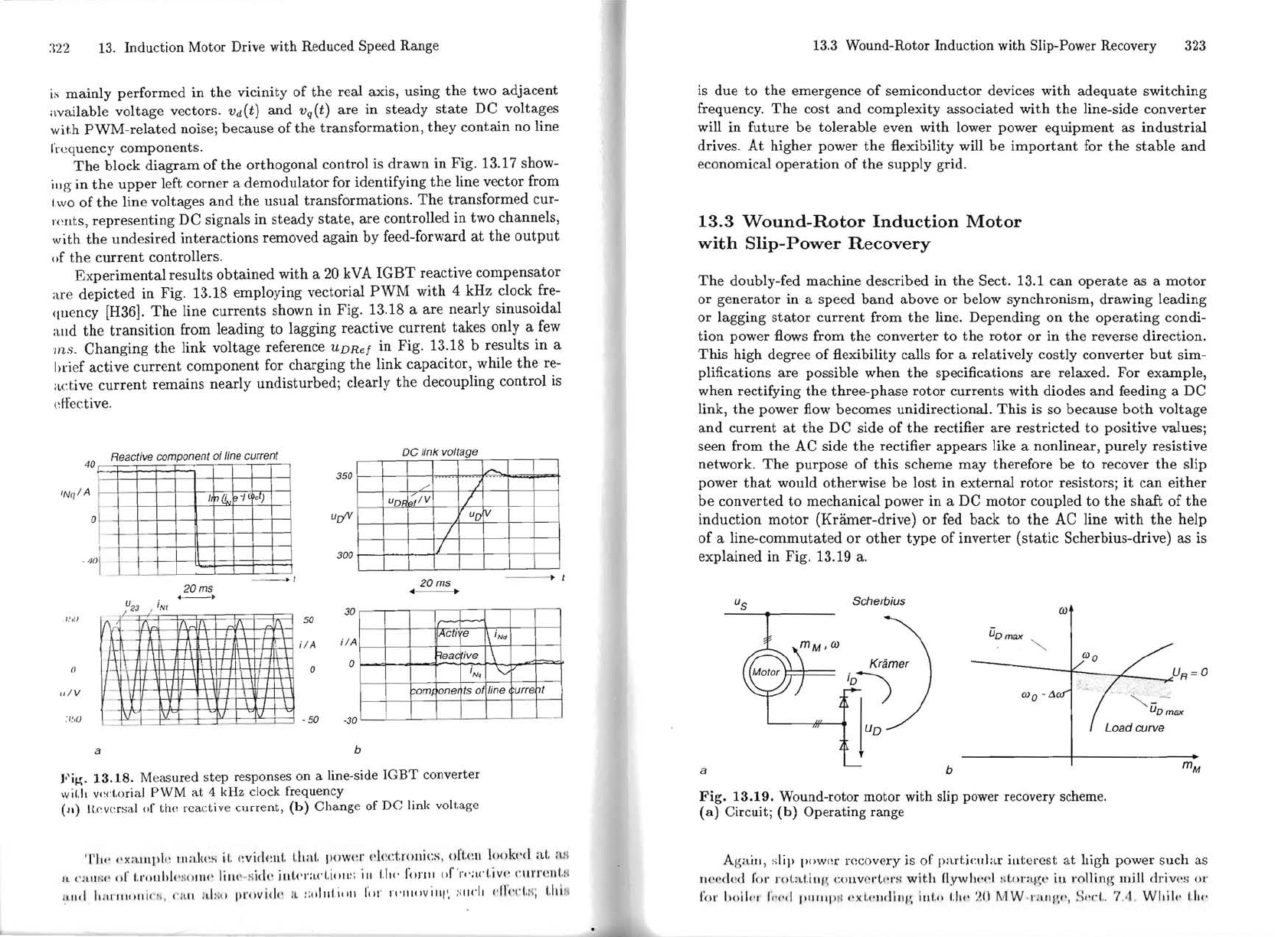
13,2 Line-side voltage source converter
321
i
Nq
I +
)
i
Nq'
control/er
i
Nq
U
D
I~
<n.,
I~I~
ó+~-:
~
_
----'-
__
_
U
Nd
t
l'
I_
Ir:: ~
1m
i
NdR
•
f
i
Nd
'control/er
,
n'
iNb
iNd
Fig.
13.17.
BIock
diagram
of
the
orthogonal
controI
of
the
line-side
converter
1L
= v
a
+ j
vb
=
V12
-
v23
e-h
=uD/2[(Sl -
S2)
-
(S2
-
S3)e-
h
]
jvrr
/
3
= uD/4[(2S
1
-
S2
- S3) +
jV3(S2
-
S3)]
=
UD
e , (13.40)
where
1/
=
0,1,2
.
..
5.
The
switching combinations result in a six-pointed
star
for
the
voltage vector
1L(
t);
in addition
there
are
the
two zero vectors
(SI, S2,
S3)
=
(-1,
-1,
-1)
and
(1,1,1),
when
the
converter terminaIs are
short
circuited
at
the
upper
or lower DC bus.
When
neglecting
the
protective intervals
and
applying
the
equivalences
given in Eqs. 13.21,
the
link
current
iDN
may
be expressed by
the
line cur-
rents,
iDN =
SliNl
+ S2iN2 + S3iN3
==
1/3
[(2S
1
-
S2
- S3)iNa +
V3
(S2
- S3)iNb];
(13.41 )
during
the
zero vector intervals
the
line currents
are
bypassing
the
DC-link,
iDN =
O.
The
six-pointed
star
of
the
available converter volt ages in line-voltage
coordinates, Fig. 13.16,
1L(t)
e-
j
)..
=
Vd
+ jV
q
=
UD
e
j
(vrr
/3-w
o
t)
(13.42)
rotates with
the
angular
velo city W
o
in c10ckwise direction
and
it
is
the
task
of
thc
current eontrollers
to
generate
the
needed direct
and
quadrature
volt-
;lj
;(!
CO
lllpüUClltS
('li
,l + jVq)Rc! for tran5fo
rmation
into
the
AC components
(
'(I"
-1-
J V
I1)lkj';
til(!
v(
~do
rial
Illodlllat,or
1,11(
:
1\
dd<!rlllines for each switching
lH:l'io.] '
I:,
LI\('
1l"(
'
('
1iflit
I'Y
lii
i')
lIi1h (SI
"r..,'
,.:,S:I).
III
vi,
:w
of
lh
e tI:a.} voltag
l'
V('('
1.01' '/l N
(/.),
' 1,\ (1) :I
J'2
/
'2
fi
N
ali,]
1.1«'
lol,;d
.
il'/'
, /i L
I\,
I' '/I(t)
I'
j
)..
!.II(! 1I10<1I1];d.11I1I
:~22
13.
Induction
Motor
Drive
with
Reduced
Speed
Range
is mainly performed
in
the
vicinity of
the
real axis, using
the
two adjacent
available voltage vectors.
Vd(t)
and
vq(t) are in steady
state
DC
voltages
wit.h
PWM-related
noise; because of
the
transformation,
they contain no line
I'requency components.
The
block
diagram
of
the
orthogonal control
is
drawn
in
Fig. 13.17 show-
iug in
the
upper
left
comer
a
demodulator
for identifying
the
line vector from
I.wo
of
the
line volt ages
and
the
usual transformations.
The
transformed cur-
r<
~
IltS,
representing DC signals
in
steady
state,
are controlled in two channels,
with
the
undesired interactions removed again by feed-forward
at
the
output
()f
the
current
controllers.
Experimental
results
obtained
with a 20
kVA
IGBT
reactive
compensator
are depicted in Fig. 13.18 employing vectorial
PWM
with 4 kHz clock fre-
qllency [H36).
The
line currents shown
in
Fig. 13.18 a are nearly sinusoidal
aud
the
transition
from leading
to
lagging reactive current takes only a
few
ms.
Changing
the
link volt age reference
UDRef
in Fig. 13.18 b results in a
hrief active
current
component for charging
the
link capacitor, while
the
re-
active
current
remains nearly undisturbed; clearly
the
decoupling control
is
dfective.
De
link voltage
Reactive companent af
fine
current
40
350
INq/A
o)
Ir(j
e·/
urfV
o
300
. 'Ia
I
• t
20ms
___
o
I
~
-i
.
-I-
....l-
i,
I~I
T
.
-i
.
W-\
ff-
"1\
1
i
1:
lL
j
I.
..,.,
~
-
--
U
23
, i
N t
30
1.'11)
50
ilA
>-
.
')
~
/'
uD"
fi
V
/
uD
/
1/
20ms
4
JActl
e
1\
iNd
Reac
ive
\
i
Nq
'\,:;
om,
one
ts
af
fine
I
.-
urre t
il A
o
()
o
/lIV
; I.',()
·50
·30
a
b
Fi~
.
13.18.
Measured s
tep
responses on a line-side
IGBT
converter
wil.h
v,~ct.orial
PWM
at
4 kHz clock frequency
(a)
Itc·
.
versa.1
o[
Lhe
rea.ctive
current,
(b)
Change
ofDe
link voltage
TIl<'
f')(;l.lll[lI,~
l1\akf~S
iI.
(~vid(:lI1.
Uml. pow(:r
..
kd.rol\ics,
()rl.(
~
\I
look('d
aI.
aH
II. '
·'
bll! i
f'
01'
I.l'ollld
" H
(l
JlI('
lill(,
-lii
,k
illl.f'l'af'i.ioll~;
iII
!.lI('
fU)'I1I
"f
'
r,
·;
"f'I.iv(' ('111'1"':111.1'
1.11<1
h
ll
,I"
"IO'f1
í(
"
II,
("
:
UI
I
tl
nll
provi
,
.!,'
I
I.
:;,dlll.illll
rol'
\'("'I<'Villl',
:·
"1<'1,
..t["'(,!.I'i;
I.lIÍ
II
13.3
Wound-Rotor
Induction
with
Slip-Power Recovery
323
is
due
to
the
emergence of semiconductor devices
with
adequate switching
frequency.
The
cost
and
complexity associated
with
the
line-side converter
will
in
future
be tolerable even with lower power equipment as
industrial
drives. At higher power
the
:fI.exibility will be
important
for
the
stable
and
economical
operation
of
the
supply grid.
13.3
Wound-Rotor
Induction
Motor
with
Slip-Power
Recovery
The
doubly-fed machine described
in
the
Sect. 13.1 can
operate
as a
motor
or
generator
in
a speed
band
above or below synchronism, drawing leading
or lagging
stator
current
from
the
line. Depending
on
the
operating
condi-
tion
power
:fI.ows
from
the
converter
to
the
rotor or
in
the
reverse direction.
This
high degree of :fI.exibility calls for a relatively costly converter
but
sim-
plifications are possible when
the
specifications are relaxed. For example,
when rectifying
the
three-phase
rotor
currents
with
diodes and feeding a DC
link,
the
power flow becomes unidirectional.
This
is so because
both
volt age
and
current
at
the
DC side of
the
rectifier are restricted
to
positive valuesj
seen from
the
AC side
the
rectifier
appears
like a nonlinear, purely resistive
network.
The
purpose of this scheme may therefore be
to
recover
the
slip
power
that
would otherwise be lost in external
rotor
resistorsj
it
can
either
be
converted
to
mechanical power in a DC
motor
coupled to
the
shaft of
the
induction
motor
(Kramer-drive) or fed back to
the
AC line with
the
help
of
a line-commutated or
other
type
of inverter
(static
Scherbius-drive) as
is
explained
in
Fig. 13.19 a.
Scherbius
(j)
ÜDmax
~
IS'
-
/'
UR=O
)
---.L
(j)
o -
Ll
~
-
-
UDmax
Loadcurve
mM
a b
Fig.
13.19.
Wound-rotor
motor
with
slip power recovery scheme.
(
a)
Circuit;
(b)
Operating
range
Ag;ülI,
~;[ip
POW(~l"
rc:c()very is of part.icular in(;erest
at
high power such as
I\(
~
(!ded
for
)'ul.;~l.illl·.
COllVf:
I·l"rs
with
H.Yw1lf'd
:iI
.
o)'al
~
\'
iu
rollin
g llIill driv('
!;
UI'
for
1,,
')
1"1
"",.,,
plllll
p
l
~
n!.f'lIdilll';
iII!."
1.11<'
:~I)
MW
1'
11
1'11,<',
~;
('(.1..
7.1\
, Whii<-
iiI<'
- 2008 — 2025 «СтудМед»