Water and Wastewater Engineering
Подождите немного. Документ загружается.


23-8 WATER AND WASTEWATER ENGINEERING
is separated from the activated sludge in a settling tank. The wastewater is discharged and the
settled activated sludge is sent to a second reactor (called a stabilization tank ) where aeration is
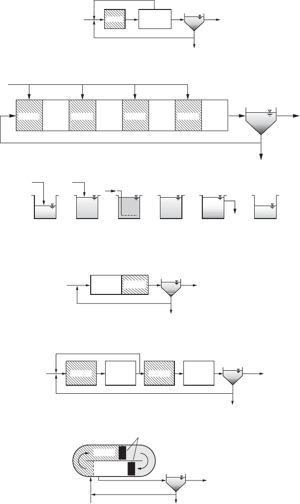
continued. Here the stored and adsorbed COD is oxidized ( Figure 23 -2g ).
The advantage of this system is the reduction in overall tank volume. The disadvantage is
that the system requires substantial operator skill and attention.
Conventional with Selector. Somewhat like the contact stabilization process, the detention
time in the selector is too short for complete BOD oxidation. The detention time is shorter than
that provided in the contac
t stabilization process. This system promotes the formation of floc that
will settle. The selector is followed by an aeration tank of conventional design ( Figure 23-2h ).
Tapered Aeration. This is an alternative to step feeding. The air supply is increased at the
head end of the conventional plug-flow tank. It is tapered to lower levels along the tank. Provided
that the inlet organic load is not so high that oxy
gen cannot be supplied to meet the demand, this
system reduces power costs and equipment sizes.
Extended Aeration. This process is used primarily to treat wastewater flows from small
residential communities. Process aeration is extended to 24 hours or
more. Under these conditions
endogenous respiration (Chapter 22, Equation 22-21) governs the oxidation process. This
minimizes the sludge mass.
While these systems can achieve good results, they have experienced problems with poor
settling sludge, low pH due to nitrification, and high suspended soli
ds in the effluent when
operated in a conventional plug-flow reactor. With adequate operator supervision, these problems
have been successfully overcome when extended aeration has been applied in an oxidation ditch.
23-3 PROCESSES FOR DENITRIFICATION
A s discussed in Chapter 22, biological nitrogen removal requires both an aerobic and an anoxic
zone. It is also referred to as nitrification-denitrification (NDN or BNDN). In addition, nitrate re-
duction requires an electron donor. This can be supplied by the influent wastewater, endogenous
respiration, or an external (exogenous) carbon sour
ce. Table 23-2 lists some of the configurations
used for biological denitrification. These are discussed in the following paragraphs.
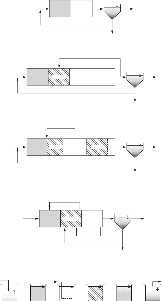
Modified Ludzack-Ettinger (MLE). This preanoxic process is one of the most commonly
used for denitrification. It relies on the return of nitrate formed in the aerobic zone to the anoxic
zone ( Figure 23-4a ). The provision of an internal recyc
le is the “mod ification” to the original
process. Both the denitrification rate and the overall nitrogen removal efficiency are increased by
this modification.
TABLE 23-2
Selected biological denitrification configurations
Preanoxic Postanoxic
Modified Ludzack-Ettinger (MLE) Single sludge
Step feed Bardenpho
TM
(4-stage)
Sequencing batch reactor (SBR) Oxidation ditch
SECONDARY TREATMENT BY SUSPENDED GROWTH BIOLOGICAL PROCESSES 23-9
Aerobic Aerobic
Return activated sludge
Mixed-liquor return
Effluent
Sludge
Influent
Anoxic Anoxic
Secondary
clarifier
Anoxic
Return activated sludge
Effluent
Sludge
Secondary
clarifier
Influent
Aerators
Aerobic
Sludge
Effluen
t
Secondary
clarifier
Return activated sludge
Aerobic
Anoxic
Aerobic
Anoxic
Aerobic
Influent
Anoxic
Aerobic
Anoxic
Fill React/aerationFill
anoxic/anaerobic
mix
Settle IdleDecant
Effluent
Influent
Air
Secondary
clarifier
Sludge
Return activated sludge
Effluent
Influent
Anoxic
Secondary
clarifier
Sludge
Return activated sludge
Internal recycle
Effluent
Influent
AerobicAnoxic
(a) Modified Ludzack-Ettinger (MLE)
(b) Step feed
(c) Sequencing batch reactor (SBR)
(d) Single-sludge
(e) Bardenpho™ (4-stage)
(f) Oxidation ditch
Preanoxic
Postanoxic
Aerobic
FIGURE 23-4
Processes for denitrification.
(Adapted from Metcalf &
Eddy, 2003.)

Step Feed. The step feed process can be modified to perform biological nitrogen removal (BNR)
as shown in Figure 23-4b . The final flow portion to the last anoxic/aerobic zone is critical in
defining the final effluent concentration of NO
3
-N as the nitrate in that zone will not be reduced.
Sequencing Batch Reactor (SBR). The SBR system for BOD oxidation and nitrification is
modified by an additional operational step ( Figure 23-4c ). Although sufficient BOD and fill time
are available to remove almost all of the nitrate after the settle and decant steps, a separate mixing
step without aeration provides more flexibility a
s well as improved nitrogen removal.
Single Sludge. In this process a mixed anoxic tank follows the aerobic tank ( Figure 23-4d ).
To achieve a high nitrate removal efficiency, a long detention time in the anoxic tank is required
because the denitrification rate is proportional to the endogenous respiration rate.
Bardenpho
TM
(4-Stage). Both preanoxic and postanoxic processes are incorporated in the
Bardenpho four-stage process ( Figure 23 -4e ). The hydraulic detention time of the postanoxic
stage is about the same or longer than the preanoxic stage. In actual practice it was discovered
that phosphorus rem
oval also occurred. The process name is derived from the inventor’s name
(Barnard, 1974) and the truncation of “denitrification” and “phosphorus” removal.
Oxidation Ditch. By increas ing the length of the oxidation ditch to provide an anoxic zone
after the aerobic zone, BNR can be achieved in a single tank ( Figure 23-4f ). Most of the BOD is
removed in the aerobic zone. Nitrate is us
ed for endogenous respiration. A large tank volume and
long sludge retention times are required for efficient BNR.
23-4 PROCESSES FOR PHOSPHORUS REMOVAL
A s discussed in Chapter 22, biological phosphorus removal (BPR) requires an anaerobic zone
followed by an aerobic zone. The alternating exposure to anaerobic and aerobic conditions can
be accomplished in the main biological treatment process (called mainstream ) or in the retu rn
sludge stream (called side stream) There are several mod
ifications to the basic process. Among
the most common are those that incorporate biological nitrogen removal. Table 23-3 lists some of
the mainstream configurations used for BPR. These are discussed in the following paragraphs.
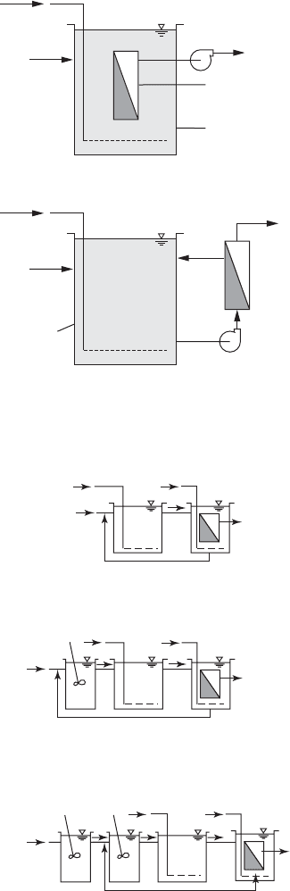
Phoredox. This is the name given by Barnard (1975) to represent any anaerobic/aerobic
sequ
ence to promote BPR. It is shown in Figu re 23-5a . A version of this process with multiple
stages is patented as A/O ™ (anaerobic/aerobic). Thes e processes are not designed to promote
nitrification/denitrification (Metcalf & Eddy, 2003). The anaerobic detention time is 30 min to 1 h.
The SRT of the aerobic zone is 2 to 4 d.
TABLE 23-3
Selected mainstream biological
phosphorus removal configurations
Phoredox
Anaerobic/anoxic/aerobic (A
2
/O™)
Bardenpho™ (5-stage)
University of Cape Town (UCT)
Sequencing batch reactor (SBR)
23-10 WATER AND WASTEWATER ENGINEERING
Fill Anaerobic
react (mixed)
Aerobic Anoxic
(mixed)
Settle Decant
Effluent
Influent
Air
Secondary
clarifier
Sludge
Effluent
Return activated sludge
Influent
Anaerobic Aerobic
Secondary
clarifier
Recycle
Sludge
(containing P)
Effluen
t
Return activated sludge
Influent
Anaerobic
Aerobic
Anoxic
Secondary
clarifier
Recycle
Sludge
(containing P)
Effluen
t
Return activated sludge
Influent Anaerobic Aerobic
Aerobic
Anoxic Anoxic
Secondary
clarifier
Anoxic recycle
Anoxic (nitrate) recycle
Sludge
(containing P)
Effluent
Return activated sludge
Influent Anaerobic Aerobic
Anoxic
(a) Phoredox (A/O
TM
)
(b) A
2
/O
TM
(c) Modified Bardenpho
TM
(5-stage)
(d) UCT (standard and modified)
(e) SBR with biolo
g
ical phosphorus removal
FIGURE 23-5
Processes for biological phosphorus
removal.
(Adapted from Metcalf & Eddy,
2003.)
SECONDARY TREATMENT BY SUSPENDED GROWTH BIOLOGICAL PROCESSES 23-11
23-12 WATER AND WASTEWATER ENGINEERING
A
2
/O ™ . This is a proprietary modification of the A/O ™ process that provides internal recycle
and an anoxic zone for denitrification ( Figure 23-5b ). The detention period in the anoxic zone is
approximately 1 h.
Bardenpho ™ (5-Stage). This modification of the four-stage process provides for both denitri-
fication and phosphorus removal (
Figure 23-5c ). The staging and recycle differ from the A
2
/O
™
process. The five-stage process uses a longer SRT than the A
2
/O ™ and thus increases the carbon
oxidation capability.
University of Cape Town (UCT). The UCT process was developed at the University of Cape
Town in South Africa. It is similar to the A
2
/O ™ process with two exceptions. The return sludge
is recycled to the anoxic stage instead of the aeration stage, and the internal recycle is from the
anoxic stage to the anaerobic stage ( Figure 23-5d ). By returning the sludge to the anoxic stage,
the introduction of nitrate to the anaerobic stage is avoided. This improves the phos
phorus uptake.
The internal recycle feed provides increased organic utilization in the anaerobic stage.
Sequencing Batch Reactor (SBR). The six operational steps of the SBR denitrification process
are retained, but the conditions are modified ( Figure 23-5e ). One alternative is to provide an anoxic
period after sufficient aerobic time has elapsed
for nitrification to occur. Another alternative is to use
cyclic aerobic and anoxic periods during the react period. This minimizes the nitrate concentration
before settling. Little nitrate is available to compete for rbCOD during the fill period so that rbCOD
uptake and storage by PAOs can occur instead of rbCOD consumption by nitrate reducing bacteria.
23-5 BIOLOGICAL TREATMENT WITH MEMBRANE SEPARATION
M e mbrane biological reactors (MBRs) consist of a biological reac tor with suspended biomass
and solids separation by mic rofiltration (MF) or ultrafiltration (UF) membranes. They may be
used with any of the processes described in the previous sections of this chapter. Membranes are
intro
duced in Chapter 9. MF filtration theory, practice, and design are discussed in Chapter 12.
The following discussion focuses on the application to wastewater systems in contrast to the water
treatment applications discussed in Chapter 12.
Process Description
MBRs have two fundamental process arrangements: (1) integrated systems that have membranes
immersed in an activated sludge reactor and (2) separate systems that have a membrane module
placed outside the reactor ( Figu re 23-6 ). Immersed membranes
using hollow-fiber or flat sheet
membranes are the most popular for several reasons. They operate at lower pressures, readily
accommodate variations in the types of biosolids found in activated sludge bioreactors, concen-
trate biosolids without settling concerns, and, typically, have a lower life cycle cos
t for municipal
systems. Separate systems use pressure-driven, in-pipe cartridge membranes. These are more
prevalent in industrial settings (Metcalf & Eddy, 2003; WEF, 2006b).
Process arrangements for implementation of MBR for nitrification, nitrogen removal,
and complete biological nutrient removal (BNR) are illustrated in Figure 23-7 . In contrast to
c
onventional activated sludge or typical BNR processes, the volume of s ludge returned to the
aeration basin is on the order of 400 percent of the wastewater flow.
SECONDARY TREATMENT BY SUSPENDED GROWTH BIOLOGICAL PROCESSES 23-13
(a)
(b)
Air
Air
Influent
Influent
Effluent to
disinfection
Effluent to
disinfection
Membrane
module
Membrane
separation
unit
Bioreactor
Bioreactor
FIGURE 23-6
S chematic diagram of membrane bioreactors: ( a ) immersed
membrane, ( b ) external membrane. ( Source: Metcalf &
Eddy, 2003.)
Air
Air
Influent
Return activated sludge
Permeate
Aeration tank
Membrane tank
Air
Influent
Influent
Air
Air
Return activated sludge
Return activated sludge
Permeate
Anoxic
tank
Aerobic
tank
Membrane
tank
Anoxic
tank
Anaerobic
tank
Aerobic
tank
Membrane
tank
Air
Permeate
(a) Car
bonaeous BOD oxidation and nitrification
(b) Nitrogen removal
(c) Complete biological nutrient removal
FIGURE 23-7
Process arrangements for membrane bioreactors (MBR).
23-14 WATER AND WASTEWATER ENGINEERING
23-6 SUSPENDED GROWTH DESIGN PRINCIPLES
Overview
The design principles of suspended growth processes may be broadly separated into two categories:
those based on experience and those based on microbial biochemistry and microbial population
dynamics. Facultative oxidation ponds fall into the first category. The re
maining suspended growth
treatment systems fall into the second category. In the following discussion the basic biological reac-
tions of the facultative oxidation pond are discussed as well as the empirical basis for their design.
The completely mixed, conventional plug-flow, and batch reactor
models that are presented
in the next section serve as means of showing the relationship between several design variables
for suspended growth processes. Mass balance relationships and applied microbial biochemistry
relationships provide the basis for other process design relationships.
Oxidation Ponds
Although empirical expressions have been developed for the design of oxidation ponds, the design
of facultative ponds is generally governed by prescriptive requirements of state regulatory agencies.
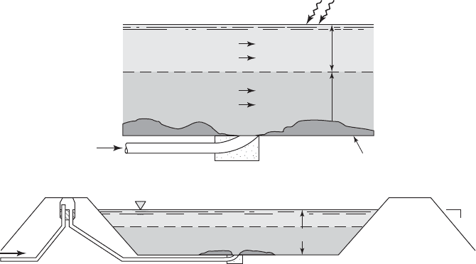
Facultative Ponds. A schematic representation of a facultative pond operation is given in
Figure 23-8 . Raw wastewater may enter at the center of the pond
or at one end. Suspended
solids contained in the wastewater settle to the pond bottom, where an anaerobic layer develops.
Microorganisms occupying this region do not require molecular oxygen as an electron acceptor
in energy metabolism, but rather use some other chemical species. Both acid fermentation and
methane fermentation occur in the bottom sludge deposits.
The facultative zone exists just above the anaerobic zone. This means that molecular oxygen
will not be available in the region at all times. Generally, the zone is aerobic during the daylight
hours and anaerobic during the hours of darkness.
Energy
Aerobic
zone
Anaerobic
zone
Sludge
Inlet
1.5 m
3
1
Organic Acids CH
4
CO
2
Organic Acids
Organic compounds
Organic compounds O
2
CO
2
H
2
O
Algae O
2
CO
2
H
2
O Light
FIGURE 23-8
S chematic diagram of facultative pond relationships. ( Source: Davis and Cornwell, 2008.)
SECONDARY TREATMENT BY SUSPENDED GROWTH BIOLOGICAL PROCESSES 23-15
Above the facultative zone, there exists an aerobic zone that has molecular oxygen present at
all times. The oxygen is supplied from two sources. A limited amount is supplied from air diffu-
sion across the pond surface. However, the majority is supplied through algal photosynthesis.
Completely Mixed Reactor Model
In 1970, Lawrence and McCarty proposed a model of the activated sludge proc ess based on
microbial biochemis try and microbial population dynamics. It serves as starting point for
understanding the design principles used in biological treatment reactor design. It is ba
sed on the
Monod equation (Chapter 22, Equation 22-16) and mass balances across a defined volum e for
specific constituents of interest such as biomass and substrate.
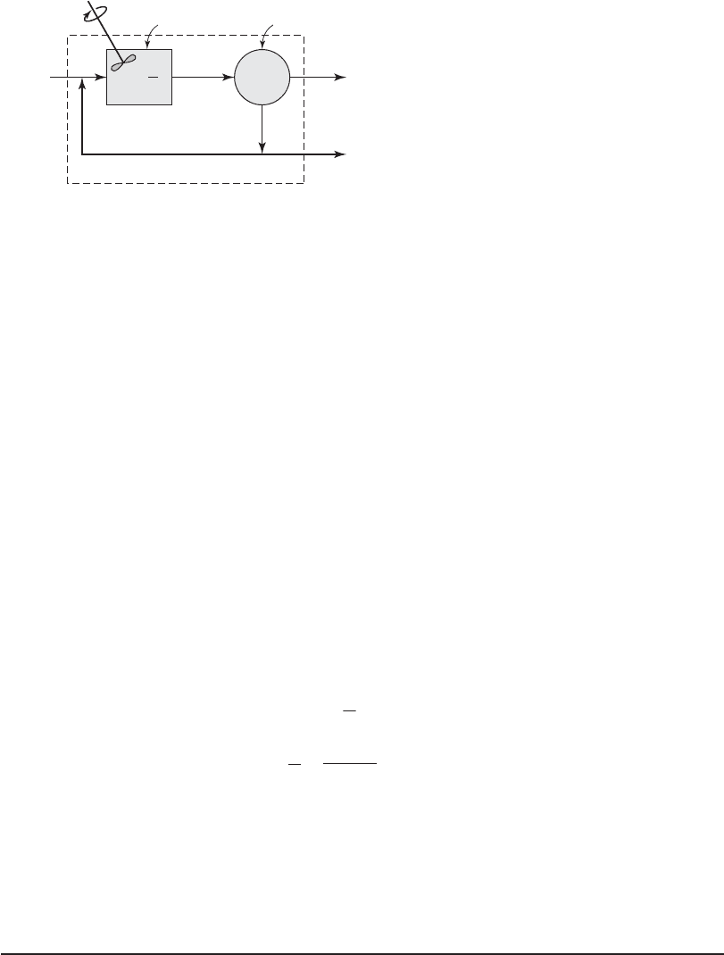
Mass Balance for Biomass. A mass balance diagram for the completely mixed system (CSTR)
is shown in Figu
re 23-9 . The mass balance equations are written for the system boundary shown
by the dashed line. Two mass balances are required to define the design of the reactor: one for bio-
mass and one for substrate ( readily biodegradable soluble chemical oxygen demand, rbsCOD).
U n der steady-state conditions, the mass balance for biomass
may be written as:
Biomass in Net biomass Biomass in Biomass
inffluent growth effluent wasted
(23-1)
The biomass in the influent is the product of the concentration of microorganisms in the
influent (X
o
) and the flow rate of wastewater ( Q ). The concentration of microorganisms in the
influent (X
o
) is measured as suspended solids * ( mg/L). The biom ass that grows in the aeration
tank is the product of the volume of the tank (
V
) and the Monod expression for growth of micro-
bial mass (Equation 22-16):
()
m
s
d
SX
KS
kX
⎛
⎝
⎜
⎞
⎠
⎟
V
(23-2)
The biomass in the effluent is the product of flow rate of treated wastewater leaving the plant
(Q Q
w
) and the concentration of microorganisms that does not settle in the secondary clarifier
( X
e
). The flow rate of wastewater leaving the plant does not equal the flow rate into the plant
because some of the microorganisms must be wasted. The flow rate of wasting ( Q
w
) is deducted
from the flow exiting the plant.
(Q + Q
r
)
Q
r
, X
r
, S
Return sludge
(Q Q
w
), S, X
e
Q
w
, X
r
, S
Q, S
0
, X
0
X, S
X, S, V
Aeration tank
Secondary
settling tank
FIGURE 23-9
Completely mixed biological reactor with solids
recycle. ( Source: Davis and Cornwell, 2008.)
*Because the model is for soluble COD, the COD of the suspended solids in the influent is not considered. This problem is
addressed in Example 23-1.

23-16 WATER AND WASTEWATER ENGINEERING
The biomass that is wasted is the product of the concentration of microorganisms in the WAS
flow ( X
r
) and the WAS flow rate ( Q
w
). The narrative mass balance equation may be rewritten as
QX
SX
KS
kX Q Q X QX
m
s
dwewr0
( ) ( )
⎛
⎝
⎜
⎞
⎠
⎟
V
(23-3)
The variables are summarized as follows:
Q wastewater flow rate into the aeration tank, m
3
/ d
X
o
microorganism concentration (volatile suspended solids or VSS) * entering aeration
tank, mg/L
volume of aeration tank m,
3
V
m
maximum growth rate constant, d
1
S readily biodegradable soluble COD (rbsCOD) in aeration tank and effluent, mg/L
X microorganism concentration (mixed-liquor volatile suspended solids or MLVSS) **
in the aeration tank, mg/L
K
s
half velocity constant
soluble BOD
5
concentration at one-half the maximum growth rate, mg/L
k
d
decay rate of microorganisms, d
1
Q
w
flow rate of liquid containing microorganisms to be wasted, m
3
/ d
X
e
microorganism concentration (VSS) in effluent from secondary settling tank, mg/L
X
r
microorganism concentration (VSS) in sludge being wasted, mg/L
Mass Balance for Substrate. At steady-state, the mass balance equation for substrate (rbsCOD)
may be written as
Substrate in Substrate Substrate in Substratte in
influent consumed effluent WAS
(23-4)
The substrate in the influent is the produ
ct of the concentration of rbsCOD in the influent ( S
0
) and
the flow rate of wastewater ( Q ). The substrate that is consumed in the aeration tank is the product
of the volume of the wastewater in the tank
( )
V
a n d the expression for the rate of substrate uti-
lization
( )
()
SX
YK S
m
s
⎛
⎝
⎜
⎞
⎠
⎟
V
(23-5
)
The substrate in the effluent is the product of flow rate of treated wastewater leaving the plant
( Q Q
w
) and the concentration of rbsCOD in the effluent ( S ). The concentration of rbsCOD in
*Suspended solid s means that the material will be retained on a filter, unlike dissolved solids such as NaCl. The amount of
suspended solids that volatilizes at 500 C 50 C is taken to be a measure of active biomass. The presence of nonliving organic
particles in the influent wastewater will cause some error (
usually small) in the use of VSS as a measure of biomass.
**Mixed-liquor volatile suspended solids is a measure of the active biomass in the aeration tank. The term “mixed liquor”
implies a mixture of activated sludge and wastewater. The phrase “volatile suspended solids” has the sa
me meaning as in the
definition of X
o
.

SECONDARY TREATMENT BY SUSPENDED GROWTH BIOLOGICAL PROCESSES 23-17
the effluent ( S ) is the same as that in the aeration tank because it is assumed that the aeration tank
is completely mixed. Because the rbsCOD is soluble, the secondary settling tank will not change
the concentration. Thus, the effluent concentration from the secondary settling tank is the same
as the influent con
centration.
The substrate in the waste activated slu dge flow is the product of the conc entration of
rbsCOD in the effluent ( S ) and the WAS flow rate ( Q
w
). The narrative mass balance equation for
steady-state conditions may be rewritten as
QS
o
SX
YK S
QQSQS
m
s
ww
( )
()
()
⎛
⎝
⎜
⎞
⎠
⎟
V
(23-6)
where Y yield coefficient (see Equation 22-17).
To develop working design equations the following assumptions are made:
1 . The influent and effluent biomass concentrations are negligible compared to that in the
reactor.
2. The influent substrate ( S
0
) is immediately diluted to the reactor concentration in accor-
dance with the definition of a CSTR.
3. All reactions occur in the CSTR.
From the first assumption the following terms may be eliminated from Equation 23-3 : QX
o
and
( Q Q
w
) X
e
because X
o
and X
e
are negligible compared to X. Equation 23-3 may be simplified to
( )
SX
KS
kX QX
m
s
dwr
⎛
⎝
⎜
⎞
⎠
⎟
V
(23-7)
For convenience, Equation 23-7 is rearranged in terms of the Monod equation:
m
s
wr
d
S
KS
QX
X
k
⎛
⎝
⎜
⎞
⎠
⎟
( )
V
(23-8)
Equation 23-6 may also be simplified and rearranged in terms of the Monod equation:
m
s
S
KS
QY
X
S
o
S
⎛
⎝
⎜
⎞
⎠
⎟
()
V
(23-9)
Noting that the left side of Equations 23-8 and 23-9 are the same, set the right-hand side of these
equations equal and rearrange to give:
QX QY
S
o
Sk
wr
d
()
XXV
V
(23-10)
Two parts of this equation have physical significance in the design of a c ompletely m ixed acti-
vated sludge system. The inverse of Q / V is the hydraulic detention time ( ) of the reactor:
Q
V
(23-11)