Water and Wastewater Engineering
Подождите немного. Документ загружается.

17-20 WATER AND WASTEWATER ENGINEERING
An example application would be a multistory hospital or laboratory connection to a water
main. The water main could potentially have a lower pressure than the building because of
fire demand, and water from instrument washing sinks could flow into the water main.
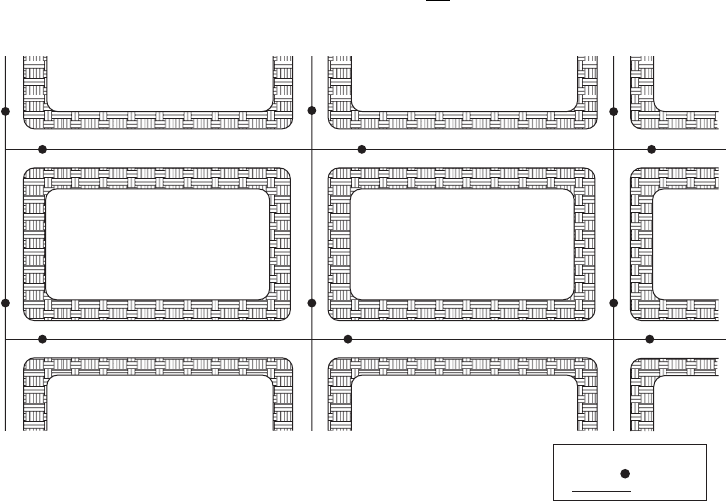
Valve Placement. GLUMRB (2003) recommends that distribution system
valves be located at not
more than 150 m intervals in commercial districts and at not more than one block or 250 m in other
districts. It is common to place valves so that sections may be isolated for repairs while continuing
to provide service to other segments of the system. An exam
ple is illustrated in Figure 17-7 .
Hydrant Spacing
GLUMRB (2003) recommends that hydrants be placed at each street intersection and at
intermediate points recommend ed by the State Insurance Services Office. This placement
ranges from 70 to 300 m. Fire departments normally require a maximum lineal distance between
hy
drants of 90 m in congested areas and 180 m in light residential districts AWWA (1998). The
actual distance between hydrants is dependent on the amount of hose the local fire department
normally carries.
Minor Losses
The headlosses that occur due to bends, elbows, joints, valves, and so on are often referred to as
minor losses. In some instances this is a misnomer because they may be greater than the losses
due to pipe friction. The general equation for estimating these losses is Equation 3-6, repeated
here for convenience:
hK
v
g
f
2
2
(17-6)
Valve
Key
Water main
FIGURE 17-7
Location of valves in a distribution system.
STORAGE AND DISTRIBUTION SYSTEMS 17-21
where K energy loss coefficient.
Energy loss coefficients are given in Appendix C. The values are for pipes greater than or equal
to 300 mm. For each decrement of 25 mm less than 300 mm, increase K by 5 percent.
An alternate method of expressing the minor losses is in terms of the equivalent length of
pipe that has
the same headloss for the same flow rate. The equivalent length is then added to
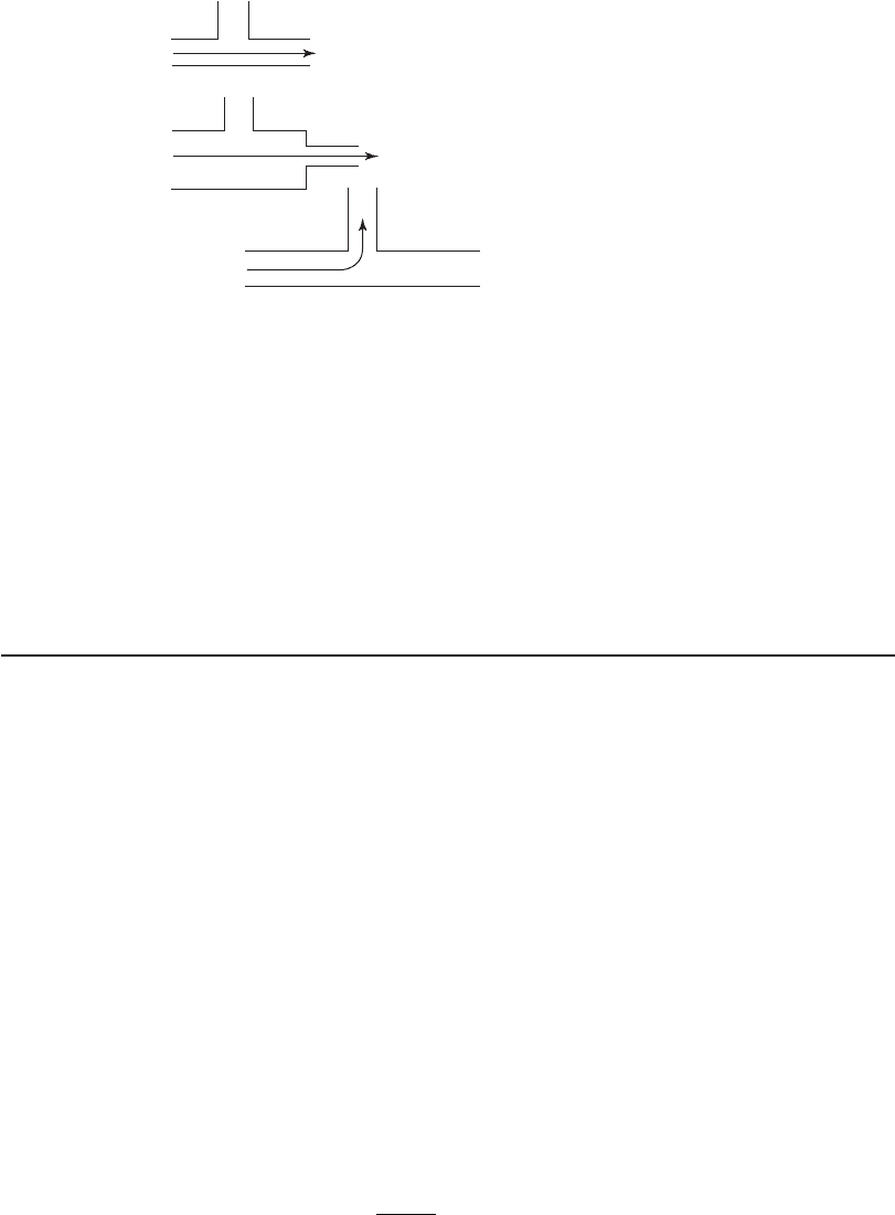
the actual pipe length for calculation of the headloss for the run of pipe. A nomograph given in
Appendix C provides a convenient method for making the headloss estimate. Figure 17-8 pro-
vides an explanation of some of the vocabulary used in the nomograph.
E xample 17-5 illu
strates the equivalent length of pipe method for estimating minor losses.
Example 17-5. Using Figure 17-2 and the data from Example 17-4 , estimate the equivalent
length of pipe and the total headloss for the pipe run from A to C and from C to D. Assume the
valves are fully open gate valves and all elbows are medium sweep.
Solution:
From A to C
1 . Using the nomograph in Appendix C, plot a line starting at the 100
mm nominal diam-
eter to the dot on the vertical line that is connected to “fully open” gate valve. Read the
equivalent length of pipe to be 0.8 m.
2. Us ing the nomograph in Appendix C, plot a line from the 100 mm nominal diameter
to the dot on the vertical line that is connected to the medium sweep elbow. Read the
equivalent length of pipe to be 2.6 m.
3. Add these lengths to the length of pipe from A to C.
08 26 45 76155 2.. .. .mm mm m
4. Using the headloss per 100 m from Example 17-4 , estimate the headloss for the pipe run
to be:
5 8
100
55 2 3 2
.
..
m
m
mm()
1. Run of standard tee
3. Standard tee through a side outlet
2. Run of tee reduced 1/4
FIGURE 17-8
N o mograph nomenclature.

17-22 WATER AND WASTEWATER ENGINEERING
From C to D
1 . The tee at Point C is a standard tee through a side outlet. It is followed by a sudden con-
traction from 100 mm to 50 mm. This contraction is followed by a fully open gate valve
and 12.2 m of 50 mm pipe.
2. Using the nomograph in Appendix C, starting at the 100 mm nominal diameter, plot a
line to the dot on the vertical line that is connecte
d to the standard tee through a side
outlet. Read the equivalent length of pipe to be 5.6 m.
3. Using the nomograph again, noting the instructions at the top of the figure, plot a line
from the 50 mm diameter to the dot on the vertical line that is connected to the sud-
den contraction ( d / D 50 mm/100 mm 1/2). Read the equivalent length of pipe to
be 0.6 m.
4. Using the nomograph again, plot a line to the d
ot on the vertical line that is connected to
the fully open gate valve. Read the equivalent length of pipe to be 0.35.
5. Add these lengths to the length of pipe from C to D.
12 2 5 606035 18 75.... .mmm m m
6. Using the headloss per 100 m from Example 17-4 , estimate the headloss for the pipe run
to be:
86
100
18 75 16
.
..
m
m
mm()
Comments:
1 . Note that in the case of the sweep elbow, the error that results from ignoring the minor
losses is on the order of 5% while the sequence of “minor losses” in going from C to D
amounts to an error of more than 35% if the minor losses are ignored.
2. Whether the estimate is performed using equations or the nomograph, it is an estimate.
Sanks (2006) warns that the minor loss estim
ate may vary from 20 to 30 % or
more.
17-5 STORAGE TANK DESIGN
Tank Terminology
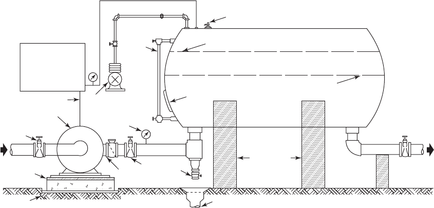
The terms tank and reservoir are used interchangeably. Hydropneumatic tanks are pressurized by
placing air in the tanks ( Figure 17-9 ). They are suitable for very small populations ( 600 people)
when storage for fire protection is not provided. When fire protection is required, a separate fire
pump is used. Hydropneumatic tanks cannot su
pply the required volume of water for fire fight-
ing. They also may be used at a booster station that provides a pressure boost in the system. If
the tank is constructed so that the bottom is at or near ground level, the tank is referred to as a
ground level tank or just a ground storage tank. If the ground storage tank is significantly taller
than it is wide, it is usu
ally referred to as a standpipe. The classic “water tower” is referred to as
an elevated storage tank.
STORAGE AND DISTRIBUTION SYSTEMS 17-23
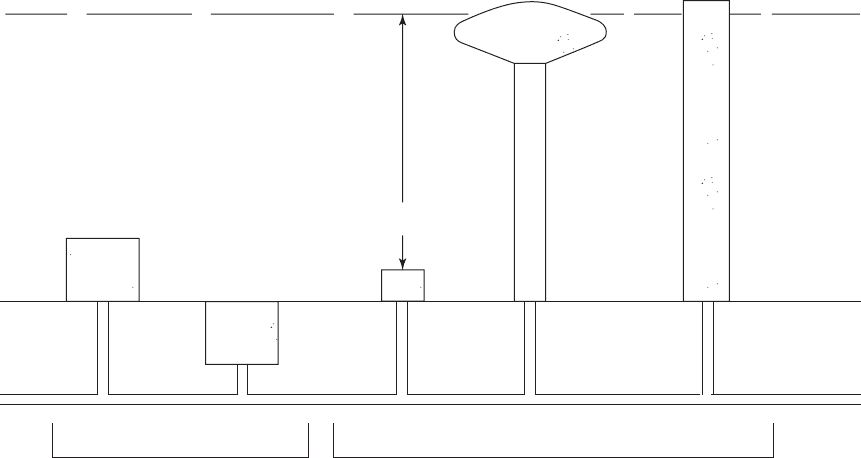
Pumped storage refers to water that is stored below the hydraulic grade line in ground tanks
or below ground tanks. The water can leave the tank only by being pumped. Tanks that float-on-
the-system have storage located at elevations such that the hydraulic grade line outside of the tank
is virtually the same as the water level in the tank. Figure 17-10 illustrates the tank terminology
.
Clearwell storage i s provided at the end of the water treatment plant. If located at ground
level or below ground level, this is pumped. It may serve the multiple functions of storage, con-
tact for disinfection, and supply for backwash water.
Location
One of the purposes of providing storage is for equalization, that is, to provide a mechanism to
level out the production of the water treatment plant while the customer demand varies widely
over the course of the day. Elevated storage is a common means of providing equalization both
in capacity and pressure. Another reason for providing elevated
storage is that it is a means of
storing energy. Because there are extra charges for electricity to pump during high electrical
demand (and high water demand), the elevated storage can offset this charge by filling the tank
when demand is low. In addition, some utilities have time-of-day pricing that allows for lower
rates at night when
demand is low for both power and water. Water stored at night when water
demand and electric pricing are low can be used during the day to reduce energy usage and
cost.
The location of the storage tank with respect to the location of the water treatment plant and
the center of demand is a major consideration in the design of the storage tank. Three generic
location
s are (1) at the sou rce (well or water treatment plant), (2) between the source and the
Tank supports
Drain
Drain
Swing check
Gate valve
Pressure gage
Air compressor
To motor
Pressure control,
high and low
pressure switch
Water
column
Air relief valve
Water level at maximum operating pressure
Water level at minimum operating pressure
Manhole
Discharge
Centrifugal pump
Gate
Intake
Plank
Cork pad
Note:
Use special rubber hose fitting between pump
and pressure tank for quiet operation.
FIGURE 17-9
T ypical installation of pressure storage tank and centrifugal pump for a small water supply.
( Source: Environmental Sanitation by Joseph A. Salvato, Jr., published by John Wiley & Sons, Inc., New York, 1958.)
17-24 WATER AND WASTEWATER ENGINEERING
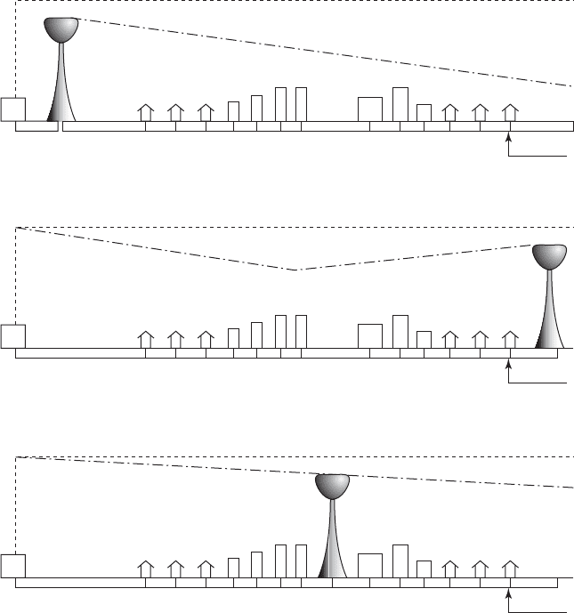
demand center, and (3) on the downstream side of the demand center. These are illustrated in
Figure 17-11 . The height and location of the tank may require a Federal Aviation Administration
(FAA) permit.
Very large communities ( 100,000 people) may not provide elevated storage. Because the
variation in demand is
small compared to the average demand, the relatively small changes in
demand are met with pumping from underground storage.
At the Source. For small communities ( 3,300 people), where little or no treatment is pro-
vided and the distance from the source to the demand center is sm
all, elevated storage located at
or near the source may be an appropriate economic decision ( Figure 17-11 a). Although placing
the tank at the source is the easiest arrangement for hydraulic analysis, it is the least useful place-
ment in terms of fire fighting or equalization of pressure.
Elevated storage at the source ma
y also be appropriate for larger systems where multiple
tanks will be used because the elevated storage at the source may be used to provide head for
backwashing the filters.
On the Downstream Side of the Demand Center. This is generally the best place to locate
an elevated storage tank. For routine operation, this arrangement allows flow to reach the center
of demand from two dire
ctions ( Figure 17-11 b). The flow carried by any individual pipe will be
lower and pipe sizes may be smaller. In addition, during fires water can flow from more than one
direction toward the fire location.
FIGURE 17-10
Tank terminology.
Pumped
system
Hydraulic grade line
∆P in
hydropneumatic tank
Elevated
tank
Standpipe
Ground surface
Water main
Float-on
system
Hydropneumatic
tank
Buried
tank
Ground
tank
STORAGE AND DISTRIBUTION SYSTEMS 17-25
Between the Source and the Demand Center. This is an intermediate choice in terms of
desirability. Terrain, land availability, and cost considerations may make this the most logical
location. The location decision should be based on a thorough hydraulic analysis.
Multiple Tanks in the Pressure Zone. If multiple tanks are required in a pre
ssure zone, they
should be placed at approximately the same distance from the source. If one tank is close to the
source and the other tanks are far away, it may be difficult to fill the remote tanks without shutting
off or overflowing the tank that is close to the source unless it is provided with an altitude valve.
For the same reason, it is essential that all of the tanks have virtually the same overflow elevation.
Multiple Pressure Zones. When multiple pressure zones are required, s ufficient storage vol-
ume should be placed in each zone. It is a waste of energy to pump water from a lower pressure
zone to storage in a higher pressure zone and then have it flow back down to the lower zone
because of lack of storage in the lower pressure zone.
FIGURE 17-11
Generic locations of elevated storage: ( a ) at the source, ( b ) downstream of the demand center, ( c ) intermediate location.
Total energy
Hydraulic grade line
Distribution pipe
Pump
station
Pump
station
Pump
station
(a)
(b)
(c)
Total energy
Hydraulic grade line
Distribution pipe
Total energy
Hydraulic grade line
Distribution pipe

17-26 WATER AND WASTEWATER ENGINEERING
Tank Levels
The most significant decision about a tank in terms of distribution system design is its overflow eleva-
tion. This elevation and the minimum, average-day, bottom of the tank will determine the size and
boundary of the pressure zone that can be served from the tank, as well as the layout of the transmis-
sion mains and
the required pumping head (Walski, 2000b). GLUMRB (2003) recommends that the
maximum variation between high and low levels in the storage tank not exceed 10 m ( 100 kPa).
The pressure zone is located on a contour map by plotting the overflow elevation and the
highest and lowest elevations of customers that can be served within the design pressure bound-
aries
(e.g., 240 kPa to 550 kPa). In general, pressure zone hydraulic grade lines should differ by
about 30 m from one pressure zone to the next (Walski, 2000b).
Volume
For small systems not providing fire protection, GLUMRB (2003) specifies that the minimum
storage capacity shall be equal to the average daily consumption. A historically more conserva-
tive rule-of-thumb is to provide capacity equal to two to three days average daily consumption.
This may
be excessive with the recognition that a long storage time results in increased formation
of disinfection byproducts, as well as decay of chlorine residual.
For those communities that elect to provide fire protection, the sizing of the tank requires a
more complex evaluation. For the purpose of this evaluation, the volum
e of the storage tank may
be conceptually divided into three layers: *
1 . Domestic water demand is fed to the distribution system from the top 3 to 5 m. As the
water level drops, the tank controls open, and the high service pumps start pumping to
fill the tank. This is called
equalization storage.
2. The next layer, amounting to 30 to 50 percent, is reserved for fire demand.
3. The bottom layer is termed emergency storage. It can still supply a minimum pressure of
140 kPa.
Equalization Storage. The design of this storage is to enable the source to operate at a prede-
termined rate. The fraction of daily water pro
duction that must be stored depends on the individ-
ual community and the operational mode selected. Table 17-8 shows how the ty pe of operation
affects the volume required.
Type of operation
Equalization volume required
as a fraction of maximum daily
demand
Constant pumping 0.10 to 0.25
Follow demand 0.05 to 0.15
Off-peak pumping 0.25 to 0.50
Variable speed pumps 0
TABLE 17-8
Operation effects on equalization storage
Source: Walski, 2000b.
*Although stratification may occur, the water is not, or perhaps more correctly, should actually not be in layers.

STORAGE AND DISTRIBUTION SYSTEMS 17-27
Fire Storage. The flow from fire storage required in excess of the equalization storage is given
by (Walski, 2000b):
SSR NFF MDD PC ES SS FDS
(17-7)
where SSR storage supply required, m
3
/h
N FF needed fire flow, m
3
/h
MDD maximum daily demand, m
3
/h
PC production capacity, m
3
/h
ES emergency supply, m
3
/h
SS suction supply, m
3
/h
FDS fire department supply, m
3
/h
The emergency supply is the water that can be brought to the system through connection with
other systems. The suction supply is the supply that can be taken from nearby open water bodies.
The fire department supply is water that can be brought to the fire by trucks.
The SSR in flow units is converted to volume by us
ing the ISO assumed duration of a fire.
A selection of duration values from the ISO is given in Table 17-9 .
Emergency Storage. Storage that is located below the tank level that provides a minimum
of 240 kPa but above the minimum fire pressure of 140 kPa is sometimes referred to as emer-
gency storage because a utility would only allow the pressure to fall to this level du ring an
emergen
cy. There is no formula to estimate this volume. If a utility has a single source without
auxiliary power and a relatively unreliable distribution system, a significant amount of emer-
gency s torage should be provided. In contrast, if a utility has multiple sources an
d treatment
facilities with an auxiliary power supply, the amount of emergency storage that should be
provided is minimal.
Example 17-6. Using the data in Example 17-3 , estimate the required storage volume assum-
ing it is a rural residential community of single family dwellings
that will supply fire protection.
Assume that the production capacity of the well system is twice the average day demand and that
off-peak pumping will be used to equalize the storage. Auxiliary generator power is available.
There is no ES, SS, or FDS.
Required fire flow,
m
3
/h
Required duration,
h
570 or less 2
680–790 3
900–1,000 4
1,100–1,250 5
1,360–1,475 6
TABLE 17-9
Required duration for fire flow
A dapted from ISO.

17-28 WATER AND WASTEWATER ENGINEERING
Solution:
a . The NFF is estimated from Table 17-3 . A conservative estimate is 455 m
3
/h. By rule,
round to the nearest 60 m
3
/h or 480 m
3
/h.
b. The MDD is estimated using the average daily demand from Example 17-3 (4,640 m
3
/ d)
and a peaking factor of 2.2 average day from Chapter 2.
()( )2 2 4 640 10 208 4253
333
., , .m /dm/d or m /h
c. The PC is twice the average daily demand from Example 17-3 .
2 4 640 9 280 387
333
(),,m /dm/d or m /h
d. The SSR is then
SSR m /h m /h m /h m /h 480 4253 387 518 3
333 3
..
e. From Table 17-9 , the required duration is 2 h. The fire storage required is
()( )2 518 3 10366
33
h m /h m..
f. Because off-peak pumping will be used to equalize the storage, from Table 17-8 one-
half the maximum daily demand will need to be stored.
()( )0 5 10 208 5 104
33
., ,dm/dm
g. Because there are two wells, auxiliary power, and storage is provided for fire flow, no
emergency storage will be provided.
h. The total storage volume required is
10366 5 104 61406
33 3
.
,,
.mm m
V
Comments:
1 . The actual storage tank volume selected would be the next standard size larger than the
calculated volume.
2. This is quite a large tank for a small community. A different mode of operation, for example,
constant pumping, a less conservative estimate of the off-peak pumping storage (25%
rather than 50%), or the provision of another well might res
ult in a more reasonable and
economical size.
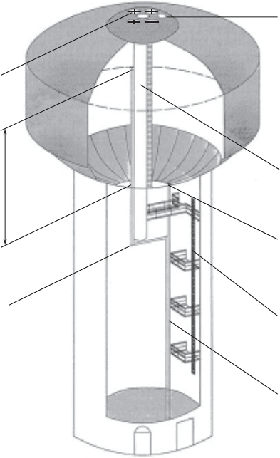
Appurtenances
Appurtenances are subordinate or adjunct parts of an apparatus—in this case the water tank. Of
the several appurtenances to the water tank, the following have been selected for discussion: riser
pipe, overflow pipe, and vents. These are illustrated in Figure 17-12
STORAGE AND DISTRIBUTION SYSTEMS 17-29
Riser Pipe. This pipe is connected to the distribution system and the bottom of the tank. Water
flows into the storage tower and drains from the tank back into the distribution system through
this pipe. For tanks that float on the system, the tank will drain only if the hydraulic grade line
outside of the tank falls below the water level in the tank. When the water level reaches a pre-
determined
lower elevation, a signal is sent to the pumping facility and pumping is increased to
raise the hydraulic grade line and pump water into the tank.
Overflow Pipe. The overflow pipe is a pipe that discharges water from the top capacity line
in an emergency when the pumps fail to shut off. GLUMRB (2003) specifies that the pipe be
brought down to an elevation between 0.30 and 0.60 m from the groun
d surface and discharge
over a drainage inlet structure or a splash plate. No overflow may be connected directly to a
sewer or a storm sewer. The overflow pipe must be screened with a twenty-four mesh noncorrod-
ible screen at its discharge point.
FIGURE 17-12
Water tower appurtenances.
Head range
Overflow elevation
Top
c
apa
c
it
y line
Botto
m
c
apa
c
it
y
line
Rainproof
hatches
Vent
Access tube
Riser pipe
Riser pipe
Tank access ladde
r
Overflow pipe