Water and Wastewater Engineering
Подождите немного. Документ загружается.


25-6
TABLE 25-1
Interpretation of the state point analysis
Location of
state point
Location of underflow line relative
to flux curve
Condition of
clarifier
Suggested
change
Within the flux curve
(Figure 25-4a)
Below the descending limbUnderloaded None
Within the flux curve
(Figure 25-4b)
Tangential to descending limb line Critically loaded Increase RAS flow rate to become
underloaded
Within the flux curve
(Figure 25-4c)
Above the descending limb line Overloaded Increase RAS flow rate to become underloaded
On the flux curve
(Figure 25-4d)
Below the descending limb line Critically loaded Reduce clarifier feed solids to become
underloaded
by converting to step feed or lower MLSS
On the flux curve
(Figure 25-4e)
Above the descending limb line Overloaded Increase RAS flow rate to become critically
loaded
Outside the flux curve
(Figure 25-4f)
Above the descending limb line Overloaded Reduce clarifier fee
d solids to become
underloaded by converting to step feed or lower
MLSS by lowering SRT
A dapted from Jayanayagam, 2006.
Solids flux
SP
SP
Gravity
flux
Gravity
flux
Overflow
rate
Overf
l
ow rate
Un
der flow
Un
derflow rate
rate
Solids concentration
(a)
Solids flux
Solids concentration
(b)
SP
Gravity
flux
Overflow
Solids flux
Solids concentration
(d)
SP
Gravity
flux
Overflow
rate
Un
d
erflow r
ate
Solids flux
Solids concentration
(c)
r
ate
Underflow
rate
SP
Gravity
flux
O
v
erflow
Solids flux
Solids concentration
(f)
SP
Gravity flux
Ove
rflow
r
ate
Un
d
erflow rat
e
Solids flux
Solids concentration
(e)
r
ate
Un
derf
lo
w
ra
te
FIGURE 25-4
State point (SP) analysis for varying conditions
to be interpreted with Table 25-1 . SP State
Point.

SECONDARY SETTLING, DISINFECTION, AND POSTAERATION 25-7
Example 25-1. Determine the limiting solids flux for a 35 m diameter secondary settling tank
that is being used to thicken activated sludge. Also, determine whether or not the clarifier is over-
loaded, critically loaded, or underloaded. The average plant flow rate to the clarifier is 9,200 m
3
/ d,
the activated sludge MLSS is 3,125 mg/L, and the RAS concentration is 10,000 mg/L. Data from
a batch settling analysis is shown below.
MLSS,
g/m
3
v
i
,
m/h
MLSS,
g/m
3
v
i
,
m/h
1,000 4.0 5,000 0.31
1,500 3.5 6,000 0.20
2,000 2.8 7,000 0.13
2,500 1.8 8,000 0.094
3,000 1.14 9,000 0.07
4,000 0.55
Solution:
a . Begin by computing the gravity solids flux.
C
i
, v
i
, SF
u
, C
i
, v
i
, SF
u
,
g/m
3
m/h kg/m
2
· h g/m
3
m/h kg/m
2
· h
1,000 4.0 4.00 5,000 0.311.55
1,500 3.55.25 6,000 0.20 1.20
2,000 2.8 5.60 7,000 0.13 0.91
2,500 1.8 4.50 8,000 0.094 0.75
3,000 1.14 3.42 9,000 0.07 0.63
4,000 0.55 2.20
The data in the third and sixth column are the prod uct C
i
v
i
, that is, for example,
1,000 g/m
3
4.0 m/h 10
3
kg/g = 4.00 kg/m
2
· h.
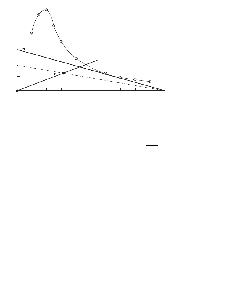
b. Plot the gravity solids flux curve as shown in Figure 25-5 .
c. Add an overflow operating line and MLSS concentration state point at 3,125 mg/L.
(1) Determine the clarifier surface area:
A
()35
4
962 11
2
2
m
m.
(2) Determine the overflow solids flux rate using Equation 25-1 :
SF
X
X
()()
()()
9 200
962 11
9 56
3
2
,
.
.
m /d
m
m/d
25-8 WATER AND WASTEWATER ENGINEERING
(3) Determine the plotting point for 3,125 mg/L or 3.125 kg/m
3
MLSS:
SF ()(9 56 3 125
24
124
3
.. )
1
.m/d kg/m
d
h
⎛
⎝
⎞
⎠
kkg/m h
3
(4) Plot the overflow rate operating line through the points (0,0) and (3,125 g/m
3
,
1.24 kg/m
3
· h)
d. Determine the limiting solids flux by drawing a line from 10,000 g/m
3
tangent to the
gravity flux curve as shown in Figure 25-5 . The limiting flux is 2.85 kg/m
3
· h.
e. A plot from 10,000 g/m
3
through the state point indicates a solids flux rate of 1.75 kg/m
3
· h.
The underflow line is below the descending limb of the gravity flux curve. This implies that
the clarifier is underloaded.
Example 25-2. Using the data in Example 25-1 , determine the recycle ratio for the underflow
concentration of 10,000 mg/L.
Solution:
a . From Figure 25-5 , the solids flux is 1.75 kg/m
3
· h for the line drawn through the state
point.
b. Using Equation 25-3 , the operating curve slope is
Slope
kg/m h kg/m h
g/m
()
(
175 0
01
22
3
.
00
0175
3
kg/m
m/h
)
.
c. The underflow velocity is then
Underflow velocitym/h m /
h
()0175 0175..
6.0
5.0
4.0
3.0
2.0
1.0
1,000 2,000
SP
Limiting flux
3,000 4,000 5,000
Solids concentration,
g
/m
3
Solids flux, kg/m
2
· h
6,000 7,000 8,000 9,000 10,000
FIGURE 25-5
Gravity flux curve for Example 25-1 .

SECONDARY SETTLING, DISINFECTION, AND POSTAERATION 25-9
d. The clarifier overflow rate (OFR) is
OFR
9 200
962 11 24
0 398
3
2
,
.
.
m /d
m h/d
m/h
()()
e. The recycle ratio ( R ) is then
R
0175
0 398
04397 0 44
.
.
..
m/h
m/h
or
f. As a check, calculate the recycle ratio based on a solids mass balance.
XQ Q QX
RR R
()
with
R
Q
Q
R
then
XRX
R
()1
and
R
X
X
R
1
1
1
10 000
3 125
1
⎛
⎝
⎞
⎠
⎛
⎝
⎜
⎞,
,
mg/L
mg/L
⎠⎠
⎟
04545 045..or
Comment. These estimates of the recycle ratio are, in essence, the same.
Secondary Settling Design Practice
M uch of the discussion about primary settling tank design in Chapter 21 is also applicable to
secondary settling tanks. This discussion focuses on the factors that must be considered because
of the large volume of flocculent solids from the secondary biological processes
.
The most popular configurations for secondary settling tanks are rectangular and circular. A
well-designed rectangular tank can be expected to perform similarly as a well-designed circular
tank. No observable differences in clarification performance at average or peak hydraulic load
ing
rates have been attributed to shape alone (WEF, 1998).
Redundancy. Multiple units capable of independent operation are required for all plants where
design average flows exceed 380 m
3
/ d (GLUMRB, 2004). It has been argued that with current
advances in materials and technology, downtime is minimal and a smaller number of larger clarifiers
has both economic advantages and more reserve peak flow capacity. For example, for larger plants
six larger clarifiers may be a better option than twelve smaller ones (Albert
son and Wilson, 1997).
Hydraulic Load. The recommended hydraulic load should be either the peak four-hour flow
of the peak day of the year, or some more extreme peak flow in systems where wet weather
flow greatly exceeds normal weather flow (Young et al., 1978).

25-10 WATER AND WASTEWATER ENGINEERING
Flow Control. When multiple units are in service, the flow must be split so that both the
h ydraulic load and the solids load are in proportion to the design limits of the tank. Methods of
balancing the flow include splitter boxes, flow control valves, hydraulic symmetry, and feed gate
or inlet port control. Some of these are discussed in Chapter 21 under the hea
dings “splitter box”
and “inlet configuration.”
Of particular concern in designing the splitter box is the potential for hydraulic restriction
and the limitations this places on operation du ring peak flow rates or when a tank is out of ser-
vice. The splitter box must be able to pass the peak hydraulic load plus the maximum return
sl
udge flow rate.
Inlet Design. Inlet configurations for circular and rectangular tanks are discussed in Chapter 21.
Overflow Rate. The calculation of overflow rate is based on wastewater flow rate (Q
in
) instead
of the mixed-liquor flow rate, that is, Q
in
alone and not Q
in
Q
R
. The overflow rate is equivalent
to the upflow velocity. The return sludge portion of the flow (Q
R
)is drawn off the bottom of the
tank and does not contribute to the upflow velocity.
The overflow rate design criteria differ for trickling filter, activated sludge, integrated fixed-
film activated sludge (IFAS), and moving bed biofilm reactors (MBBR) secondary settling tanks.
The recommendations for each are di
scussed in the following paragraphs.
• Trickling filter: The historic use of high overflow rates and shallow secondary clarifiers
resulted in poor performance. For shallow tanks, a conservative average overflow rate
of 0.09 m/h with a maximum overflow rate of 0.28 m/h is suggested (Vesilind, 2003).
GLUMRB (2004) specifies a peak hourly overflow rate of 2.0 m/h. Clarifier
designs for
trickling filters should be similar to designs used for activated sludge process clarifiers
with appropriate feedwell size and depth, increased sidewater depth, and similar hydraulic
overflow rates (Metcalf & Eddy, 2003). Recommended overflow rates as
a function of side-
water depth are summarized in Table 25-2 .
• Activated sludge: The previous two editions of the WEF design manual (WEF, 1998) sug-
gested the following maximum allowable overflow rates at the minimum recommended
TABLE 25-2
Recommended trickling filter secondary clarifier
overflow rates
Sidewater
depth, m
Average
overflow rate,
m/h
Maximum
overflow rate,
m/h
2 0.4 0.75
3 0.8 1.6
4 1.2 2.2
5 1.4 2.8
Data compiled from Jayanayagam, 2006, and Metcalf & Eddy,
2003.

SECONDARY SETTLING, DISINFECTION, AND POSTAERATION 25-11
TABLE 25-4
Secondary clarifier overflow rates for IFAS processes
Sidewater
depth, m
Average
overflow rates,
m/h
Peak
overflow rate,
m/h Comment
4.3 m 0.7–1 1.7
Deep in excess of 1.7 With flocculator center
well and baffles to prevent
wall currents
A dapted from Jayanayagam (2006).
sidewater depths: 1.4 m/h at average flow, 2.4 m/h for the three-hour sustained peak flow
rate, 2.7 m/h for the two-hour sustained peak flow rate.
A survey of design firms revealed that they prefer to select conservative overflow rates.
A compilation of preferred overflow rates is shown in Table 25-3 .
• Integrated fixed-film activated sludge (IFAS): The overflow rates for IFAS processes as a
function of sidewater depth are shown in Table 25-4 .
• Moving bed biofilm reactors (MBBR): The recommended range of overflow rates for
MBBRs is 0.5 to 0.8 m/h (Metcalf & Eddy, 2003).
E xample 25-3 illustrates the check on overflow rate for a design based on solids loading.
TABLE 25-3
Preferred secondary clarifier overflow rates for activated sludge processes
A dapted from Metcalf & Eddy, 2003, and Lakeside Equipment Corporation.
Flow rate
Average flow
overflow rates,
m/h
Peak flow
overflow rate,
m/h Comments
Conventional
activated sludge 0.68–1.2 1.7–2.7
Extended aeration 0.33–0.68 1.0–1.3
Oxidation ditch0.51–0.68 1.7
Biological
nutrient removal (BNR) 0.68–1.2 1.7–2.7
Biological phosphorus
removal
Total P 2 mg/L 1.0–1.3
Total P 1 mg/L 0.67–1.0 Occasional chemical
addition
Total P 0.2 to 0.5 mg/L 0.50–0.83
Continuous chemical
addition
25-12 WATER AND WASTEWATER ENGINEERING
Example 25-3. Check the overflow rate for the secondary clarifier diameter selected in
E xample 25-1 .
Solution:
a . The average plant flow rate to the clarifier given in Ex ample 25-1 is 9,200 m
3
/ d . The
surface area was calculated as 962.11 m
2
.
b. The overflow rate is
v
Q
A
0
3
2
9 200
962 11 24
040
,
.
.
m /d
m h/d
m/
()()
ddor 0.017 m/h
c. In comparison with Table 25-3 , this is conservatively low for conventional and BNR
processes.
Comment. In selecting the diameter of the secondary settling tank for activated sludge pro-
cesses, the design diameter must be checked for both overflow rate and solids loading. The larger
of the diameter
s that results from these calculations governs the design.
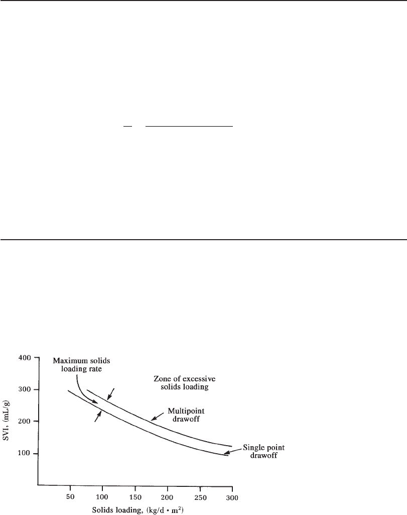
Solids Loading. When data are available to perform a solids flux or state point analysis, this is
the preferred method for determining the solids loading rate. Previous editions of the WEF design
manual (WEF, 1998) provided a graphical approach using Figure 25-6 to s
elect an appropriate
solids loading rate. In the absence of test data, most design engineers prefer to keep the maxi-
mum solids loading rate, including full RAS c apacity, in the range of 100 to 150 kg/m
2
· d
(Jayanayagam, 2006). Table 25-5 summarizes typical design ranges.
FIGURE 25-6
Design solids loading versus SVI. ( Note: Rapid sludge removal design assumes that there will
be no inventory in the settling tank. Source: WEF, 1998.)

SECONDARY SETTLING, DISINFECTION, AND POSTAERATION 25-13
Sidewater Depth. Liquid depth in the secondary clarifier is measured at the sidewall in circular
tanks and at the effluent end wall of rectangular clarifiers. Based on historical operating data,
Parker (1983) demonstrated that at similar overflow rates, suspended solids in the effluent
decreased with inc
reasing depth. He also found that variability in effluent quality also decreased
with increasing depth.
Most firms agree that larger tanks require greater depth. However, cost considerations
generally restrict depths to less than 4.5 to 5 m. The suggested depths in Table 25-6 appear to
be reasonable for circular tanks
. Although it is suggested that they may also apply to rectangular
tanks, the method of application is not stated. In addition, it suggested that rectangular tanks may
not need to be as deep (WEF, 1998).
Weir Loading. GLUMRB (2004) specifies that plants with a capacity less than 3 ,800 m
3
/ d
should not have a hydraulic loading greater than 250 m
3
/ d · m of weir length at peak hourly flow.
For plants larger than 3,800 m
3
/ d, the weir loading rate is specified as less than 350 m
3
/ d · m.
C urrent design consensus is that weir placement and c onfiguration have more effect on
clarifier performance than the hydraulic loading.
Weir Configuration and Baffles. Suggestions for weir placement, configuration, and baffles
are given in Chapter 21.
A dapted from Metcalf & Eddy, 2003, and Lakeside Equipment Corporation.
Flow rate
Average solids
loading rates,
kg/m
2
· h
Peak solids
loading rates,
kg/m
2
· h
Conventional activated sludge 4–6 8
Extended aeration 1.0–5 7
Oxidation ditch 12
Biological nutrient removal 5–8 9
TABLE 25-5
Ranges of loading rate for activated sludge process secondary clarifiers
TABLE 25-6
Final settling basin side water depth
Side water depth, m
Tank diameter, m Minimum Recommended
12 3.0 3.7
12 to 20 3.4 3.7
20 to 30 3.7 4.0
30 to 43 4.0 4.3
43 4.3 4.6
A dapted from WEF, 1998.
25-14 WATER AND WASTEWATER ENGINEERING
Sludge Removal. The most common sludge collector for rectangular tanks in the United States
is the chain-and-flight system. Although traveling bridge collectors have been used extensively
in Europe, they have not become popular in the United States. The chain-and-flight system is
described in Chapter 10.
At lower MLSS conc entration
s (1,000 to 2,000 mg/L) rectangular clarifiers have worked
well. At the higher MLSS concentrations of biological nutrient removal processes, their capacity
may be signific antly reduced. F requently, this reduction is due to the transport capacity of the
scraper mechanism. Albertson (2008) presents the following recommend
ations to overcome this
limitation:
1 . Define the maximum transport requirements (RAS flow) based on the solids loading rate
and the return sludge concentration. The lower return concentration consistent with the
highest weekly sludge volume index (SVI) should be employed.
2. Establi
sh the longitudinal scraper height and speed based on the theoretical transport
capacity equal to 125 percent of the maximum RAS flow.
3. Provide variable speed drives for the longitudinal collectors. The speed range should be
at least 0.61–2.44 m/min.
4. Replace cross-collectors with sludge
collection headers.
5. Provide about 0.9 m additional depth (or 2.5 percent of basin length) at the inlet end in
new basins to minimize peak flow sludge accumulation at the effluent end.
6. The maximum length of the longitudinal collector may be in the range of 45.7–48.8 m
with peak solids loading rates of 5.1 kg/m
2
· h. Longer basins will need two collection
troughs or a trough near the center of the tank.
There is no general consensus as to which sludge mechanism is optimal for circular tanks.
In the late 1980s, the majority of firms favored hydraulic suction when the plants were nitrify-
ing, and the primary clarifiers were effective in removing debris that
might clog the suction
mechanism. Hydraulic suction mechanisms lift solids from across the entire tank radius. A
hydraulic head differential is created by the use of pumps or adjustable valves. There are two
ty pes of hydraulic suction systems: the organ pipe, or riser pipe, an
d the m anifold or header
system. The riser pipe system has a separate collector pipe for each suction inlet orifice. A
v-shaped plow directs the sludge to the pipe. The manifold system uses a horizontal pipe with
orifices along its length.
S craper mechanisms are favored because they presumably allow a thic ker RAS and
lower
RAS flow rates, and create less turbulence in the tank. There are two types: those with straight
scraper blades and those with spiral plows. The multiblade plow has been used most extensively
in the United States. For lighter suspended growth sludges, the spiral plows are gaining favor
(Tekippe, 2006).
Sludge transport, treatment, and disposal are
discussed in Chapter 27.
Scum Removal. Suggestions for scum removal systems are given in Chapter 21.
Sludge Blanket Depth. The sludge blanket depth is not a design parameter. However, it has
several operational impacts that demonstrate the need for adequate depth to store sludge, as well
SECONDARY SETTLING, DISINFECTION, AND POSTAERATION 25-15
as adequate sludge removal c apacity, and the selection of the design overflow rate. Peng et al.,
(2007) found the following full scale tests:
• The sludge blanket level has a strong linear correlation with the surface overflow rate
(SOR). Increasing SOR leads to an increase in the blanket level regardless of sludge blan-
ket height.
• When a high SOR is applied to the clarifier, increasing the RAS may not reduc
e the blanket
level.
• Low initial blanket levels do not help achieve a lower blanket level under high SOR.
• Critical blanket levels are determined by the sludge settleability. High blanket levels show
a strong linear correlation with effluent total suspended solids.
Tank Dimensions. Rectangu lar tank lengths are seldom greater than 110 m and are typically
30 to 60 m. Historically, wid ths have been limited to 6
m by the slud ge scraping mechanisms.
Multiple parallel flights have expanded this width to 24 m. Recent advances in fiberglass com-
posites have allowed single flight widths to be increased to 10 m. Current practice is to provide a
depth of approximately 4 to 5 m. (Pettit, 2006).
Although circu
lar tanks up to 100 m in diameter have been built, most engineers select
diameters less than 50 m to avoid wind effects. In keeping with recommended sidewater depths,
typical depths are in the range of 4 to 5 m.
25 -3 DISINFECTION
Introduction
A goal of the Clean Water Act is, in essence, to make the nation’s water “fishable and swim-
mable.” Thus, unlike drinking water disinfection, the purpose of wastewater disinfection is to
reduce pathogen concentrations to acceptable levels. Each state s ets their standards based on
water quality. This standard may be s
easonal to take into account recreational activities. Seasonal
disinfection has become less prevalent in recent years. Regulatory agencies are requiring year-
round disinfection bec ause the adverse effects of residual chlorine are eliminated by the use of
UV disinfection or by chemical d
echlorination.
Bacterial effluent limits may be included in the NPDES permit. For example, municipal waste-
water treatment plants in Michigan must comply with limits of 200 fecal coliform bacteria (FC)
per 100 mL of water as a monthly average, and 400 FC/100 mL as a seven-day average. More strin-
gent requirements are im
posed to protect waters that are used for recreation. Total-body-contact
recreation waters must meet limits of 130 Escherichia coli per 100 mL of water as a 30-day aver-
age and 300 E. coli per 100 mL at any time. Partial-body-contact recreation is permitted for water
with less than 1,000 E. coli per 100 mL of water.
Disinfection theory and di
sinfection chemistry are discussed in Chapter 13. The discussion in
this section begins with a summary of dechlorination chemistry. The remainder of the discussion is
on the use of chlorine (Cl
2
gas and NaOCl liquid) and ultraviolet light for wastewater disinfection.
Dechlorination
Methods for neutralizing the chlorine after disinfection are required to reduce toxic effects on
natural biota and to reduce the production of disinfection byproducts. The common compounds