Wang X. Vehicle Noise and Vibration Refinement
Подождите немного. Документ загружается.


© Woodhead Publishing Limited, 2010
Table 12.5 Engine confi guration and reciprocating imbalance forces
Engine confi guration First-order
force
First-order
moment
Second-order
force
Second-order
moment
Counterbalancing
Inline four-cylinder 0 0 Yes 0 Second-order requires counter-rotating
balance shafts
Inline six-cylinder 0 0 0 0 Not required
V6 cylinder with 60°
bank angle
0 Yes 0 Yes First-order requires additional crank
balancing
Second-order requires balance shaft
V6 cylinder with 90°
bank angle
0 Yes 0 Yes First-order requires crankshaft balancing
and balance shaft
Second-order requires balance shaft
V8 cylinder with 90°
bank angle
0 Yes 0 0 First-order requires additional crank
balancing
Copyrighted Material downloaded from Woodhead Publishing Online
Delivered by http://woodhead.metapress.com
ETH Zuerich (307-97-768)
Sunday, August 28, 2011 12:07:49 AM
IP Address: 129.132.208.2

266 Vehicle noise and vibration refi nement
© Woodhead Publishing Limited, 2010
stiffness, the bolted joint between the two must also be suffi ciently stiff
to ensure the whole system meets it target.
• Frequency of the fi rst torsion mode and bending mode of the crank-
shaft. The crankshaft modes are susceptible to being excited to the gas
pressure loads. Tuned crank pulley dampers are often used as a
countermeasure.
• Frequency of the bending modes of the engine mounting brackets. Since
the engine forces are reacted through the engine mounting system, any
amplifi cation of engine vibrations by brackets in resonance must be
avoided (refer to the later discussion on engine mounting).
Besides the signifi cant low and mid-frequency vibrations generated by
the rotation and combustion forces of the engine, there are high frequency
sources of noise that affect the sound quality of the engine. The combustion
wavefront within the cylinder generates high frequency pressure pulses that
are audible as high frequency noise. The level of combustion noise produced
is proportional to the rate of pressure rise during combustion. Figure 12.4
shows a comparison of cylinder pressures during combustion in typical
gasoline and diesel engines. Diesel compression ignition engines have a
more abrupt explosive combustion process than spark ignition gasoline
engines, and so have a noisier and higher frequency content. The higher
cylinder pressures in diesel engines also result in high potential for piston
knocking in the cylinder clearances.
Table 12.6 Engine confi guration and combustion gas torque forces
Engine
confi guration
0.5 order 1.5 order 2 order 3 order 4 order
Inline
four-cylinder
Single
cylinder
variation
Primary Harmonic
Inline
six-cylinder
Single
cylinder
variation
Primary
V6 cylinder
with 60°
bank angle
Single
cylinder
variation
Bank-to-bank
variation
Primary
V6 cylinder
with 90°
bank angle
Single
cylinder
variation
Bank-to-bank
variation
Primary
V8 cylinder
with 90°
bank angle
Single
cylinder
variation
Bank-to-bank
variation
Primary
Copyrighted Material downloaded from Woodhead Publishing Online
Delivered by http://woodhead.metapress.com
ETH Zuerich (307-97-768)
Sunday, August 28, 2011 12:07:49 AM
IP Address: 129.132.208.2

Noise and vibration refi nement of powertrain systems in vehicles 267
© Woodhead Publishing Limited, 2010
Impacts during operation of the valve train also contribute to high fre-
quency tapping noises, and timing chain or gears are also sources of high
frequency noise within the engine.
Sources of high frequency noise are often transmitted as airborne noise
radiated from the engine surfaces. Most airborne noise is radiated from the
large thin panels on the engine. These can include cam covers, front cover,
inlet manifolds, oil pan, exhaust pipes and heat shields. The best noise
reduction countermeasure is to provide isolation of these surfaces. Where
a soft isolating joint is not acceptable, other treatments include ribbing,
dished concave/convex surfaces, laminated layers, and exterior acoustic
covers.
Examples of countermeasures applied for airborne noise include:
• Isolation of the crank pulley to the crankshaft. The crank pulley can
radiate combustion noise because it is directly mounted on the crank-
shaft. Radiated noise can be minimised by isolation and designing
spokes instead of a fl at disc hub.
• Laminated heat shields on the exhaust manifold. Plain steel heat shields
mounted directly on the exhaust system are effi cient radiators of noise.
Due to the high temperatures, it is not practical to design an isolated
connection. Choosing a multi-layer material that sounds dead due to
internal damping is a common method of noise reduction.
• Acoustic cover over the inlet manifold. Inlet manifolds often have com-
paratively thin walls with large surface areas and also act as effi cient
radiators of noise. A separate, acoustically treated cover placed over
the engine is often used to absorb the radiated noise.
Engine mounts are the key defence in isolating engine forces from the
vehicle structure, whilst also performing the key function of restraining the
Gasoline SI
3000
2000
1000
0
Diesel CI
Faster rate of pressure
rise = higher
combustion noise
Crank angle (°)
–60 –40 –20 0 20 40 60
Pressure (kPa)
Boosted diesel CI
12.4 Cylinder pressure comparison.
Copyrighted Material downloaded from Woodhead Publishing Online
Delivered by http://woodhead.metapress.com
ETH Zuerich (307-97-768)
Sunday, August 28, 2011 12:07:49 AM
IP Address: 129.132.208.2
268 Vehicle noise and vibration refi nement
© Woodhead Publishing Limited, 2010
engine in the engine bay. Although they may often appear very simple
devices, the design and placement of the mounts need to be very carefully
optimised in order to achieve satisfactory refi nement. In order to achieve
the best isolation from engine vibrations, the rigid body mounting modal
frequencies of the mount system need to be set very low. But soft mounts
must be suffi ciently durable for the life of the vehicle, as well as acting to
control the motion of the engine to prevent it from colliding into anything
housed in the engine bay.
The design considerations for engine mounting, whether front wheel
drive (FWD) or rear wheel drive (RWD), are covered in the following
steps:
• The fi rst consideration is to target the roll frequency of the engine. The
rate of the mounts must be soft enough to isolate the low frequency
torsional vibrations from the engine. In normal operation of the vehicle,
the lowest frequency vibration of concern is at idle engine speed. Thus
the rate of the mounts is chosen to provide a rigid body modal frequency
in the roll direction (torque reaction of the engine) much lower than
the engine fi ring frequency at idle.
• The second consideration is to ensure the bounce frequency of the
engine is separated from the vehicle suspension vertical (hop) modes.
It normally follows that if the roll frequency is quite low (approximately
10 Hz), then the bounce frequency will also be quite low. Humans are
sensitive to low frequencies, and should the road input excite the engine
into bounce, the ride quality of the vehicle can be seriously compro-
mised. So the desire is to separate the bounce mode of the engine from
the hop modes of the suspension. On modern cars this often is not
enough, and hydraulically damped engine mounts are used to control
engine bounce. The maximum hydraulic damping is normally specifi ed
to match the bounce frequency of either the engine or vehicle
suspension.
• Designing separation (decoupling) of all rigid body engine modes. This
ensures that engine or road inputs do not generate excessive motion of
the engine in any direction (e.g. suspension vertical input must not
excite the engine in its pitching or bounce modes).
• Placement of mounts at nodes of the powertrain elastic bending mode.
Transmission of mid-frequency vibrations can be minimised by placing
mounts at the node position.
• Snubbers/progressive mount rates. The ideal requirement is to restrain
engine roll under full load, but at the same time to maximise isolation.
If the mount stiffness is too soft, mounts could bottom-out when the
engine is under full load, causing harsh engine sound.
Copyrighted Material downloaded from Woodhead Publishing Online
Delivered by http://woodhead.metapress.com
ETH Zuerich (307-97-768)
Sunday, August 28, 2011 12:07:49 AM
IP Address: 129.132.208.2
Noise and vibration refi nement of powertrain systems in vehicles 269
© Woodhead Publishing Limited, 2010
• High frequency isolation is usually designed by targeting high stiffness
of the mount brackets and supports. As a rule of thumb, the mounting
system is targeted to provide 20 dB of isolation in high frequency vibra-
tion, and this is done by ensuring the dynamic bracket stiffness is at least
10 times the dynamic stiffness of the mounts.
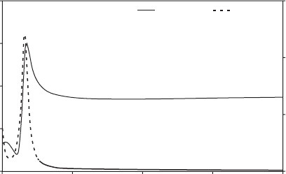
Figure 12.5 shows an example of the dynamic stiffness and damping
characteristics of a hydraulically damped engine mount. The hydraulic
damping in this mount has been designed to reach a maximum at approxi-
mately 15 Hz to minimise bounce of the engine by having it tuned at the
frequency of the vertical mode. The dynamic stiffness curve shows the
typical behaviour of a hydraulic engine mount. Dynamic stiffness is often
at a minimum prior to the peak damping frequency, and reaches a maximum
just above the peak damping frequency. A drawback of the hydraulic
engine mount is that it also behaves dynamically stiffer at mid- to high
frequencies compared to a simple rubber elastomer mount, and so there is
a loss in isolation performance of the engine mounting system. An emerg-
ing trend is to use actively controlled engine mounts to switch the hydraulic
damping off at idle to enable a smooth and refi ned idle sound quality (there
is no need for damping to restrain engine bounce when the vehicle is
stationary).
12.4.2 Accessories
The engine in a passenger vehicle will typically be used to drive a series of
accessories via a belt drive. The accessories include an alternator, an
air-conditioning compressor and a hydraulic power steering pump. Quite
2000
1500
1000
500
0
Frequency (Hz)
0 50 100
Stiffness Damping
150
15
10
5
0
200
Dynamic stiffness (N/mm)
Damping (Ns/mm)
12.5 Hydraulic engine mount dynamic stiffness and damping.
Copyrighted Material downloaded from Woodhead Publishing Online
Delivered by http://woodhead.metapress.com
ETH Zuerich (307-97-768)
Sunday, August 28, 2011 12:07:49 AM
IP Address: 129.132.208.2
270 Vehicle noise and vibration refi nement
© Woodhead Publishing Limited, 2010
surprisingly these accessories can generate equivalent noise levels to the
engine, especially under idle conditions. Thus it is important to have targets
and strategies to minimise the noise component of the accessory systems.
Each individual accessory can generate its own particular noise source,
but they are common in that the rotating components can generate an
unbalance force in addition to a periodic operating force. For a vane power
steering pump and reciprocating air-conditioning compressor, the periodic
force is due to the pumping action of the fl uid. For alternators, the periodic
force is generated by the magnetic fl ux variation as the rotor passes the
poles.
The accessory drive system is connected together by the drive belt. The
belt drive system is tuned to avoid belt slippage that can generate an alarm-
ing squealing noise. Slippage can occur due to loss of tension in the belt,
under high loads, or under high crankshaft torsional vibration. For example,
starting or stopping the engine can cause slippage on the crank pulley and
possibly excite the tensioner into resonance. Belt slippage will often occur
at the alternator pulley because the alternator has the highest angular
momentum of the accessories due to its high rotational speed. One solution
is to make use of a one-way decoupling clutch on the pulley (King and
Monahan 1999). This is effective but can be a costly solution.
The accessory drive system has torsional vibration modes, with the belt
acting as the spring elements and the accessories as lumped inertias. The
objective is to ensure that the fi rst torsional mode is low enough in fre-
quency that the engine will not excite it at idle. A crankshaft damper is
often used to lower the torsional modal frequency of the accessory system.
Each of the accessories is bolted to the engine either directly or to a
support bracket. In both cases, the objective is to ensure that the fi rst
bending frequency of the accessory mounting is suffi ciently high to avoid
being excited from either the engine or the accessory unbalanced forces.
Normally a target based upon the maximum engine fi ring frequency is
specifi ed for these purposes. The bracket design must also ensure that belt
alignment is accurate, and the surfaces are not effi cient radiators of noise.
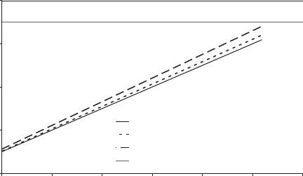
As a case study, we can consider the development of a mounting bracket
stiffness target for an alternator mounted to a V6 engine. The desire is to
ensure that the fi rst modal frequency of the mounted alternator lies above
the engine fi ring frequencies as well as above the rotating unbalanced fre-
quencies of the alternator. Figure 12.6 shows that a Campbell diagram can
be drawn to help establish the bracket modal frequency target. In this
example, the V6 engine has an operating range to 6200 rpm, and the third-
order combustion forces will have a limit of 310 Hz. Initially an alternator
pulley ratio of 3.05 : 1 is chosen, and that results in the alternator imbalance
forces reaching a maximum range of 315 Hz. However, a higher pulley ratio
should be selected to avoid the potential of beating noise between the
Copyrighted Material downloaded from Woodhead Publishing Online
Delivered by http://woodhead.metapress.com
ETH Zuerich (307-97-768)
Sunday, August 28, 2011 12:07:49 AM
IP Address: 129.132.208.2
Noise and vibration refi nement of powertrain systems in vehicles 271
© Woodhead Publishing Limited, 2010
engine fi ring frequency and alternator imbalance. For a pulley ratio of
3.3 : 1, the maximum frequency from alternator imbalance increased to
341 Hz. Thus the design target for the alternator mounting modal fre-
quency was set at greater than 350 Hz (incorporating a margin of approxi-
mately 10 Hz in this example).
12.4.3 Manual transmissions
While the gear sets in a transmission are carefully optimised to minimise
sources of noise by the manufacturer, the vehicle platform engineer must
carefully consider the successful integration of the transmission into the
vehicle system. Often there are many arguments about who is to blame for
gear whine in a new model vehicle: when the transmission manufacturer is
summoned to fi x the transmission, he may instead point towards weak-
nesses of the installation in the vehicle as the contributor.
The gear sets in a transmission are helical-cut to minimise generation of
gear noise, which normally manifests itself as a whine during run-up or
run-down. The manufacturer will do his best to ensure smooth engagement
of gear teeth to minimise forces and will design a stiff casing to minimise
radiated noise. Structure-borne whine can be minimised by following good
mounting practices to the body, using stiff brackets and soft isolators (refer
to Section 12.4.1 on engine mounting). Gear whine structure-borne paths
can also include the driveshafts and the shifter linkage.
Gear rattle is a phenomenon that plagues manual transmissions. Under
situations of high torsional vibration from the engine, the variation in rota-
tional speed of the input shaft can cause clashing of teeth between mating
pairs, causing a disturbing rattling noise. The transmission manufacturer
will remind you that a balance needs to be struck between the amount of
400
300
200
100
0
Engine speed (rpm)
1000 2000 3000 4000
Engine 3rd order
Alternator 1st order (3.05 ratio)
Alternator 1st order (3.3 ratio)
Mounting target (>350 Hz)
5000 6000 7000
Frequency (Hz)
12.6 Campbell diagram for alternator mounting target.
Copyrighted Material downloaded from Woodhead Publishing Online
Delivered by http://woodhead.metapress.com
ETH Zuerich (307-97-768)
Sunday, August 28, 2011 12:07:49 AM
IP Address: 129.132.208.2
272 Vehicle noise and vibration refi nement
© Woodhead Publishing Limited, 2010
gear lash required for economical production, and the tighter requirements
on lash to minimise rattle. So in the end, it comes down to minimising
source levels of torsional vibration from the engine and providing good
isolation of the noise transfer paths.
The fl ywheel and clutch are your allies in controlling engine torsional
vibration inputs into the transmission. The inertia of the fl ywheel assists in
smoothing engine torque, but a good balance needs to be made with engine
responsiveness. The damping springs in the clutch plate are tuned to assist
in torsional isolation. In some instances, frictional damping in the damping
springs can be applied to overcome low frequency induced gear rattle, but
needs to be treated with caution to ensure there is no noticeable degrada-
tion in high-frequency isolation. The dual mass fl ywheel is a recent inven-
tion that has been used to lower the torsional modal frequency associated
with gear rattle to a frequency well below the idle speed of the engine
(Wolfgang 1990).
12.4.4 Automatic transmissions
In many parts of the world, automatic transmissions have almost com-
pletely penetrated the automotive market. In some respects this is a bless-
ing to noise and vibration engineers because the torque converter in its
slipping state provides isolation of the torsional vibrations from the engine
crankshaft. Torsional vibration problems on manual transmissions such as
gear rattle and driveline resonances are unheard of in automatics running
in the unlocked state. But unfortunately the torque converter does not
always operate in the unlocked state. When the clutches lock up the torque
converter there is a loss of isolation to the engine. The locked state is nor-
mally restricted to light cruise loads where engine combustion torque is
near its minimum.
To further achieve the fuel economy benefi ts of a locked converter,
electronic controlled slip has been adopted to enable some degree of tor-
sional isolation from the engine. With a controlled amount of slip (typically
20 to 80 rpm) full isolation can be maintained. The noise and vibration
engineer will need to work with the transmission calibration engineer to
determine minimum acceptable levels of slip for good noise and vibration
refi nement. The transmission calibration engineer must ensure that this
minimum level of slip is carefully controlled so as not to lose slip speed,
especially under change in engine torque commanded by the driver. More
discussion on the challenges of the increasing use of a locked torque con-
verter is covered in Section 12.5.
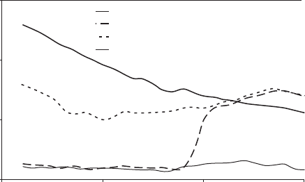
Figure 12.7 shows an example of the torsional vibration isolation of an
unlocked torque converter compared to a fully locked torque converter.
For comparison there is also a plot of torsional vibration transmitted by a
Copyrighted Material downloaded from Woodhead Publishing Online
Delivered by http://woodhead.metapress.com
ETH Zuerich (307-97-768)
Sunday, August 28, 2011 12:07:49 AM
IP Address: 129.132.208.2
Noise and vibration refi nement of powertrain systems in vehicles 273
© Woodhead Publishing Limited, 2010
torque converter running electronically controlled slip up to 1900 rpm,
whereafter the torque converter goes into the fully locked state. The chart
shows how effective controlled slip can be in reducing torsional vibration
from the engine.
12.4.5 Driveline
Many newcomers to automotive engineering fi nd it surprising that the
vehicle driveline can generate many noise and vibration challenges. Like
every other powertrain subsystem, the driveline can generate sources of
vibration, have infl uence on powertrain system modes, as well as act as
structure-borne paths.
In this chapter, the driveshaft is defi ned as the shaft that connects the
fi nal drive module to the wheels, and the propshaft as the shaft that con-
nects the transmission to the fi nal drive module in RWD vehicles. The
levels of imbalance are more critical on propshafts, since propshafts rotate
faster than driveshafts. For example, if we assume a fi nal drive ratio of 3 : 1,
then the imbalance force generated for the same out-of-balance mass will
be nine times greater on the propshaft compared to the driveshafts. This
drives the need for tighter requirements for residual imbalance and radial
run-out for propshafts. Radial runout can often account for the majority of
imbalance forces generated and the solution is to ensure the propshaft stays
straight and centred. Bolted joints require a spigot for guidance, and if
splined joints are used they need to be tight to ensure the torque load does
not drive the propshaft up the splines.
The couplings at each end of a driveshaft are also a signifi cant source of
vibration if not properly designed. The couplings are designed to enable
150
100
50
0
Engine speed (rpm)
1000 20001500
Engine torsional velocity
Open TC – propshaft torsional vibration
Locked TC – propshaft torsional vibration
Controlled slip – propshaft torsional vibration
2500
Torsional velocity (deg/s)
12.7 Driveline torsional vibration comparison between a locked, an
unlocked and a controlled slip torque converter.
Copyrighted Material downloaded from Woodhead Publishing Online
Delivered by http://woodhead.metapress.com
ETH Zuerich (307-97-768)
Sunday, August 28, 2011 12:07:49 AM
IP Address: 129.132.208.2
274 Vehicle noise and vibration refi nement
© Woodhead Publishing Limited, 2010
transmission of torque through an angular misalignment to account for
relative movement between the driveline and suspension. Constant-velocity
couplings are exclusively used on driveshafts because of the large excursion
of angles encountered during operation but come at a cost because of their
complexity. In situations where the angular misalignment is less than 1° on
a propshaft, a universal joint might be used to keep costs down. However,
universal joints are not constant-velocity and this means that the shaft
output speed will vary in proportional to the angle across it and generate
a second-order torque, so it is important to note that universal joints are
only suitable for driving across small angles if good noise and vibration
refi nement is required.
A long propshaft will need to be designed as two or more sections of
tube to avoid whirling or bending at high vehicle speeds. A multi-tube
propshaft will require support bearings placed next to the centre joints. A
propshaft support bearing will be rubber mounted to isolate it from the
vehicle body. In order to minimise the path of high frequency vibrations
transmitted from the engine, support bearings with low natural frequencies
and low damping are desirable. However, the low-frequency bounce mode
of the propshaft can be excited if the sources of vibration mentioned above
are not controlled adequately.
The fi nal drive module houses the fi nal gear set and differential. In FWD
vehicles it is incorporated into the transmission, and on RWD vehicles it is
mounted at the rear of the vehicle. The gear set in a fi nal drive module
is a source of gear whine, particularly noticeable under light loads. This is
because a hypoid gear tooth profi le is used on the crown and pinion
gears, and under low loads, and hypoid gears tend to have higher transmis-
sion errors.
The housing of the fi nal drive module has traditionally been cast from
iron. One of the benefi ts of iron is that the thermal expansion of the housing
matches the gear sets, thus minimising gear tooth transmission meshing
error as the temperature of the module varies. But a cast iron fi nal drive
module is very heavy and has become a target for vehicle mass reduction.
Aluminium housings are now used extensively but suffer from potentially
higher levels of gear whine due to thermal expansion in operation.
Sometimes RWD fi nal drive modules are directly mounted on the vehi-
cle’s rear suspension sub-frame, but this provides poor isolation of mid- to
high frequency vibration such as gear whine. Conversely, the module can
be mounted on rubber isolators but needs careful management of rigid
body modes to ensure that modes are not excited by the driveline imbal-
ance forces.
Figure 12.3 presented some elastic modes that are associated with the
engine–transmission–driveline system. Figure 12.8 provides an indication
of the elastic torsional mode defl ection shapes of the driveline system.
Copyrighted Material downloaded from Woodhead Publishing Online
Delivered by http://woodhead.metapress.com
ETH Zuerich (307-97-768)
Sunday, August 28, 2011 12:07:49 AM
IP Address: 129.132.208.2