Wang X. Vehicle Noise and Vibration Refinement
Подождите немного. Документ загружается.


© Woodhead Publishing Limited, 2010
235
11
Active noise and vibration control in vehicles
S.J. ELLIOTT, University of Southampton, UK
Abstract: Active control works by destructive interference between the
original sound or vibration fi eld in the vehicle and that generated by a
controllable, secondary, source. Physical limitations generally confi ne its
usefulness to low frequencies so that it complements conventional
passive control methods. The development of powerful processors at an
affordable cost and the increasing trend towards integration in vehicles
has allowed the commercial implementation of active control systems by
several manufacturers, mainly for the reduction of low frequency engine
noise. As vehicles become lighter to achieve fuel effi ciency targets, it is
expected that active control will play an important part in maintaining
an acceptable NVH environment, in terms of sound quality as well as
overall level.
Key words: sound, vibration, active control, sound quality, lightweight
vehicles.
11.1 Introduction
Active control involves driving a number of actuators to create a sound or
vibration signal out of phase with that generated by the vehicle, thus attenu-
ating it by destructive interference. Its successful application requires that
there is both a good spatial and a good temporal matching between the
fi eld due to the actuators, or secondary sources, and that due to the vehicle.
The requirement for spatial matching gives rise to clear limits on the upper
frequency of active noise control, due to the physical requirement that the
acoustic wavelength must be small compared with the zone of control. The
requirement for temporal matching requires a signal processing system that
can adapt to changes in the vehicle speed and load. Both the physical limi-
tations and the signal processing control strategies will be described in this
chapter, together with a description of some of the practical systems that
have found their way into production at the time of writing. Active noise
and vibration control can provide a useful alternative to passive noise and
vibration control, particularly at low frequencies and on vehicles with par-
ticular problems. Although active control has been experimentally demon-
strated in vehicles for over 20 years, it is only recently that the levels of
integration within the vehicle’s electronic systems have allowed the cost to
become affordable. Active control may now allow a reduction in the weight
Copyrighted Material downloaded from Woodhead Publishing Online
Delivered by http://woodhead.metapress.com
ETH Zuerich (307-97-768)
Sunday, August 28, 2011 12:07:04 AM
IP Address: 129.132.208.2

236 Vehicle noise and vibration refi nement
© Woodhead Publishing Limited, 2010
of conventional passive methods of low frequency noise control, helping
the push towards lighter, more fuel effi cient vehicles.
11.2 Physical principles and limits of active control
Active vibration control in vehicles often involves the isolation of a particu-
lar transmission path, particularly of engine orders through engine mounts.
Here the spatial matching problem requires that the mechanical actuator
drives in the same direction as the dominant transmission path from the
source and at more or less the same point. For this reason most systems
use combined active/passive mounts, in which the actuator is integrated into
a conventional hydromount. Although piezoelectric and magnetostrictive
actuators have been considered for this application, the most successful
actuator type appears to be electromagnetic. Cost considerations generally
limit the number of actuators that can be used, since these are generally
the most expensive parts of automotive active vibration control systems,
and so the successful use of active control is limited to vehicles with a few
dominant transmission paths. The introduction of active mounts can signifi -
cantly ease the conventional problems in trading off high static stiffness
with low dynamic stiffness.
An idealised arrangement to illustrate the function of an active mount is
shown in Fig. 11.1. The force transmitted through the mount, assuming it
behaves reasonably linearly, can be written at a particular frequency as
f
T
= f
S
+ S
M
(x
S
− x
B
) (11.1)
Passive stiffness
Source
Active force
Body
acceleration
Body
11.1 Idealised active vibration system consisting of a single active
mount, which includes passive stiffness S
M
and an actuator generating
an active force f
S
, connecting a vibration source such as an engine to
the vehicle’s body.
Copyrighted Material downloaded from Woodhead Publishing Online
Delivered by http://woodhead.metapress.com
ETH Zuerich (307-97-768)
Sunday, August 28, 2011 12:07:04 AM
IP Address: 129.132.208.2

Active noise and vibration control in vehicles 237
© Woodhead Publishing Limited, 2010
where f
S
is the secondary force generated by the actuator, x
S
is the displace-
ment of the source above the mount, x
B
is the displacement of the body
below the mount and S
M
is the mount stiffness. The body is assumed to only
be driven by this total force, so that if F
B
is the fl exibility of the body below
the mount, then
x
B
= F
B
f
T
= F
B
f
S
+ F
B
S
M
(x
S
− x
B
) (11.2)
so that solving the equation for the displacement of the body gives
x
Ff Sx
FS
B
BS MS
BM
=
+
()
+
()
1
(11.3)
If x
B
is measured using an accelerometer on the body, for example, and, at
a particular engine order, an adaptive controller is used to adjust the sec-
ondary force, f
S
, so that the output of this accelerometer is cancelled, then
it can be seen by setting equation 11.3 to zero that f
S
under these optimum
conditions must be equal to
f
S(optimum)
= − S
M
x
S
(11.4)
Notice that the required force does not depend on the fl exibility of the
body, since this has been brought to rest. Also, notice that the total force
in equation 11.1 has also been set to zero with this control force, and that
not only does this total force act down on the body but it also acts up on
the source structure. Thus, if the total force becomes zero, the source struc-
ture is effectively fl oating at this control frequency and x
S
becomes the free
displacement of the source. Equation 11.4 thus provides a useful way of
estimating the force requirements of an active mount, depending as it does
on only the mount stiffness and the free source displacement at the fre-
quency of interest. There are some advantages to measuring the total
transmitted force for use as the control signal, rather than the body accel-
eration, since it is related to the secondary force in a more straightforward
way than the latter. The measurement of the total transmitted force, using
a load cell for example, can, however, be more complicated than measuring
the acceleration.
The requirement for spatial matching is more complicated for active
noise control, since it is the acoustic fi eld inside the vehicle which must be
controlled and this is generally excited by the distributed vibration of the
whole body, excited by multiple sources. In order to illustrate the frequency
limitations of active noise control inside a vehicle, we assume that the sound
fi eld is tonal and use the complex pressure at a single frequency, ω, which
may be described in modal form as
pa
nn
n
xx,
ωω
()
=
() ()
=
∞
∑
Ψ
0
(11.5)
Copyrighted Material downloaded from Woodhead Publishing Online
Delivered by http://woodhead.metapress.com
ETH Zuerich (307-97-768)
Sunday, August 28, 2011 12:07:04 AM
IP Address: 129.132.208.2

238 Vehicle noise and vibration refi nement
© Woodhead Publishing Limited, 2010
where x is the position vector, a
n
(ω)is the amplitude of the nth acoustic
mode and Ψ
n
(x) is its mode shape.
Although in principle an infi nite number of modes must be used to
describe the sound in the enclosure, the sound fi eld can always be approxi-
mated to arbitrary accuracy with a fi nite modal series. In the low frequency
range, where active control is most effective, the modal description is a very
effi cient representation of the sound fi eld since relatively few modes need
be considered. Conventional passive noise control techniques also do not
work very well in this low frequency region, unless very massive barriers
or bulky absorbers are used, and so active control conveniently comple-
ments the effect of passive noise control techniques and can provide sig-
nifi cant weight and space savings at low frequencies.
Two active control problems will be briefl y considered: global control
and local control. The objective of a global control system is to reduce the
sound throughout the enclosure by adjusting the amplitudes and phases of
a number of secondary sources, which are typically loudspeakers. The fun-
damental limits of such a strategy can be assessed by calculating the reduc-
tions which are possible in the mean square pressure integrated over the
whole volume, which is proportional to the acoustic potential energy in the
enclosure that may be written as
E
c
pV
p
V
ω
ρ
ω
()
=
()
∫
1
4
00
2
2
x,d
(11.6)
Assuming that the mode shapes are orthonormal, E
p
(ω) is equal to the
sum of the modulus squared mode amplitudes (Nelson and Elliott, 1992).
Since the secondary sources linearly couple into each mode amplitude,
E
p
(ω) is a quadratic function of the complex secondary source strengths,
and this function has a unique global minimum. This minimum value of
E
p
(ω) provides a measure of the best performance that can be obtained in
a global control system for a given distribution of secondary sources and a
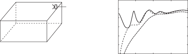
given excitation frequency. Figure 11.2(b), for example, shows the result of
a number of such calculations for the levels of E
p
(ω) at various excitation
frequencies in a computer model of an enclosure of dimensions 1.9 × 1.1 ×
1.0 m as shown in Fig. 11.2(a), which are approximately the conditions
inside a small car (Elliott, 2001). The solid line in Fig. 11.2(b) shows how
the energy due to a primary source in one corner of the enclosure varies
with excitation frequency, the dashed line shows the energy after it has been
minimised using a single secondary loudspeaker in the opposite corner, and
the dot-dashed line shows the energy after minimisation using seven sec-
ondary loudspeakers placed at all the corners of the enclosure away from
the primary. The fi rst longitudinal resonance, at about 80 Hz, is signifi cantly
attenuated by the action of a single secondary loudspeaker, but almost no
reduction is achieved in the energy at about 160 Hz, close to which three
Copyrighted Material downloaded from Woodhead Publishing Online
Delivered by http://woodhead.metapress.com
ETH Zuerich (307-97-768)
Sunday, August 28, 2011 12:07:04 AM
IP Address: 129.132.208.2
Active noise and vibration control in vehicles 239
© Woodhead Publishing Limited, 2010
acoustic modes have their natural frequencies. This is to be expected, since
in general a single loudspeaker can control only a single mode. Even with
seven secondary loudspeakers, however, a reduction in energy of only
about 5 dB is achieved at this excitation frequency and this reduction
becomes less than 1 dB at about 250 Hz.
The number of secondary sources required to achieve active control is
approximately equal to the number of signifi cantly excited acoustic modes,
which can be estimated from the modal overlap, i.e., the average number
of modes with natural frequencies within the half-power bandwidth of a
single mode (Elliott, 2001). The modal overlap in this enclosure is about
seven at 250 Hz, which explains the limited performance with seven loud-
speakers, but at higher frequencies the acoustic modal overlap in an enclo-
sure rises as the cube of the excitation frequency. This sharp rise with
frequency in the required number of secondary sources provides a very
clear upper frequency limit to global control with a system of reasonable
complexity.
An alternative strategy to global control would be to control only the
sound at specifi c locations in an enclosure, such as close to the ears of pas-
sengers in a vehicle. Such a local control strategy was originally suggested
by Olsen and May (1953) who described an active headrest using a feed-
back control system from a microphone to a closely-spaced loudspeaker
acting as the secondary source. The acoustic performance of such a system
depends on the detailed geometric arrangement of the headset and the
position of the passenger’s head, but some physical insight can be gained
by considering simplifi ed models. Figure 11.3, for example, shows a
Secondary
acoustic
source
Frequency (Hz)
(b)(a)
*
0
Total acoustic potential
energy (dB)
100
110
105
100
95
90
85
80
200 300 400
Primary
acoustic
source
11.2 (a) An active noise control system in which a loudspeaker is used
to globally control the sound in an enclosure of about the size of a
small car interior. (b) The total acoustic potential energy in the
enclosure as a function of excitation frequency, when driven by the
primary source alone (solid line), when the energy is minimised using
a single secondary source (dashed line) and when the energy is
minimised using seven secondary sources (dot-dashed line).
Copyrighted Material downloaded from Woodhead Publishing Online
Delivered by http://woodhead.metapress.com
ETH Zuerich (307-97-768)
Sunday, August 28, 2011 12:07:04 AM
IP Address: 129.132.208.2
240 Vehicle noise and vibration refi nement
© Woodhead Publishing Limited, 2010
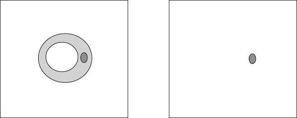
cross-section through the zone of quiet, within which the sound has been
attenuated by at least 10 dB, generated when a diffuse primary sound fi eld
is cancelled at the point x = L by an acoustic monopole at the origin (Elliott,
2001). The two graphs correspond to an excitation frequency for which L
is much smaller than the acoustic wavelength, in which case a ‘shell’ of quiet
is generated around the secondary source, and to an excitation frequency
for which L is of the order of the acoustic wavelength, in which case the
zone of quiet is spherical with a diameter which is about one-tenth of an
acoustic wavelength (Elliott et al., 1988). The rule of thumb that the spatial
extent of a local active control system is about one-tenth of a wavelength
has proved to be very useful in the initial stages of many practical designs.
11.3 Control strategies
The effective attenuation of a signal using active control requires a high
degree of temporal matching between the waveform due to the vehicle
alone and that due to the active control system. This is most easily illus-
trated with a sinusoidal signal, for which a 10 dB attenuation requires that
the two signals must be matched within about 2 dB in amplitude and within
about 20° in phase. In practice, this temporal matching is achieved by using
a control system with a sensor to monitor the residual difference between
the two signals. This ‘error sensor’ may be a microphone, or microphone
array, for an active noise control system inside a vehicle, or an accelerom-
**
–3 –2 –1 0 1
(a)
23
3
2
1
0
–1
–2
–3
x/L
L = 0.03 λ L = 0.3 λ
x/L
–3 –2 –1 0 1
(b)
23
3
2
1
0
–1
–2
–3
x/L
x/L
x/L
11.3 The zone of quiet, within which a diffuse primary fi eld is
attenuated by more than 10 dB for a local control system in which a
monopole acoustic source at the origin is arranged to cancel the
pressure at x = L for two different excitation frequencies for which (a)
L is much larger than the acoustic wavelength, and (b) L is of the
order of the acoustic wavelength.
Copyrighted Material downloaded from Woodhead Publishing Online
Delivered by http://woodhead.metapress.com
ETH Zuerich (307-97-768)
Sunday, August 28, 2011 12:07:04 AM
IP Address: 129.132.208.2
Active noise and vibration control in vehicles 241
© Woodhead Publishing Limited, 2010
eter on the chassis next to an active mount for an active vibration control
system.
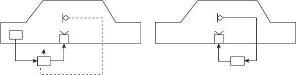
There are two different ways in which the control system can use the
signal from this error sensor: using either feedforward control or feedback
control. Idealised, single-channel feedforward and feedback controllers are
illustrated in Fig. 11.4. In addition to the signal from the error sensor, which
is illustrated as a microphone in Fig. 11.4(a), a feedforward control system
also requires an independent ‘reference’ signal, generally denoted x, that
is correlated with that being controlled. In an engine noise controller, for
example, it is the engine orders that are being attenuated and a reference
signal at the frequency of these engine orders is required, which will track
these orders as the engine speed changes. Originally, such a reference signal
was derived by analogue processing of the ignition signal, but it is now
commonly synthesised from knowledge of the engine speed supplied over
a CAN bus, for example. The signal driving the secondary loudspeaker is
obtained by adjusting the amplitude and phase of this tonal reference
signal.
It is not generally effective to operate a feedforward controller with a
fi xed response, since it is then not responsive to changes in the error signal
or the environment, i.e. it is ‘open loop’. The error signal is thus used to
adapt the response, so that it is able to change with engine speed and load,
for example, and the system then becomes ‘closed loop’. The need to adapt
the controller response means that most practical implementations use
digital electronics, operating in sampled versions of the reference and error
signals and producing a sampled signal to drive the actuator, which all need
to be fi ltered to remove components above half the sampling frequency. A
variety of algorithms have been used to adapt the controller, but most are
based on an adaptive fi ltering method called the ‘LMS’ (least mean square)
Error microphone Error microphone
Reference
signal, x
Feedforward
controller
(a) (b)
Feedback
controller
Secondary
loudspeaker
Secondary
loudspeaker
11.4 Illustration of single-channel active noise control systems using
(a) a feedforward and (b) a feedback control strategy. Note that the
feedforward control signal requires an additional reference signal, x,
and uses the error signal to adapt the controller.
Copyrighted Material downloaded from Woodhead Publishing Online
Delivered by http://woodhead.metapress.com
ETH Zuerich (307-97-768)
Sunday, August 28, 2011 12:07:04 AM
IP Address: 129.132.208.2

242 Vehicle noise and vibration refi nement
© Woodhead Publishing Limited, 2010
algorithm, which was originally developed in the 1960s for applications such
as echo cancellation on telephone lines (Widrow and Stearns, 1985). The
modifi ed algorithm required to get the controller to converge reliably in
active control applications is called the fi ltered reference LMS or ‘fi ltered
x LMS’ (Widrow and Stearns, 1985; Elliott, 2001). In practice, multiple
loudspeakers are driven to minimise the sum of the mean square responses
from a number of microphones, which requires a multichannel generalisa-
tion of the fi ltered x LMS algorithm (Elliott et al., 1988).
The feedback system, illustrated in Fig. 11.4(b), by contrast is generally
implemented with a fi xed controller and so can be effi ciently built using
analogue electronics. The feedback system has several other advantages,
such as not requiring a reference signal, but also has a number of signifi cant
disadvantages. One disadvantage is that the control is not selective, i.e. any
signal will be attenuated, not just those correlated with the reference signal.
Another disadvantage is that the error sensor, which is the microphone in
Fig. 11.4(b), must be placed close to the secondary loudspeaker.
The fundamental trade-off in the design of any feedback controller is
that between performance and stability (Franklin et al., 1994; Elliott, 2001).
The feedback system can become unstable when the loop gain, which
includes the response between the actuator and sensor and that of the
controller, has a phase shift of 180°. The feedback then changes from being
negative, which leads to an attenuation of the error signal, to being positive,
which leads to an enhancement of the error signal. All practical systems
will have a loop gain with such a phase shift at high frequencies, due to the
acoustic propagation delay from the loudspeaker to the microphone, and
thus inevitably have enhancement at some frequencies. If, however, the
loop gain is greater than unity at the frequency where this phase shift is
180°, then the feedback system will become unstable. Some mitigation of
this condition can be achieved using analogue ‘compensator’ circuits, but
sooner or later this unstable condition will arise as the feedback gain is
increased, which will then limit the performance at lower frequencies. A
phase shift of 180° is reached at a frequency for which the distance between
the loudspeaker and the microphone, d, is half an acoustic wavelength. If
c
0
is the speed of sound, the upper frequency of operation of a feedback
control system, f
(max)
, will be signifi cantly below this frequency, which is
given by c
0
/2d, so that
f
c
d
max
()
<<
0
2
(11.7)
and, in practice, the upper frequency is about one-tenth of c
0
/2d. One can
thus see that for an active headphone, for which feedback controllers are
widely used and in which d is about 1 cm, the maximum frequency will be
about 1.7 kHz, since c
0
is 340 metres per second. For an active control
Copyrighted Material downloaded from Woodhead Publishing Online
Delivered by http://woodhead.metapress.com
ETH Zuerich (307-97-768)
Sunday, August 28, 2011 12:07:04 AM
IP Address: 129.132.208.2
Active noise and vibration control in vehicles 243
© Woodhead Publishing Limited, 2010
system in a car, however, where the microphone is close to the driver’s head
but the loudspeaker is fi tted in the door or the dashboard, d will be about
50 cm and so the upper frequency will be about 34 Hz. The feedback system
is thus of limited use unless either very low frequency noise is to be con-
trolled or the loudspeaker can be brought signifi cantly closer to the micro-
phone, by mounting it in the headrest, for example. Laboratory versions of
such headrest controllers have been demonstrated (Elliott, 2001), with per-
formance up to about 300 Hz. At this frequency, however, the size of the
zone of quiet, predicted to be one-tenth of an acoustic wavelength following
the discussion in Section 11.2, is about 10 cm, so that signifi cant active
control would be experienced only if the listener’s head was fairly
stationary.
11.4 Commercial systems
Early automotive active noise systems were feedforward arrangements for
tonal engine noise control (Elliott et al., 1988), developed as part of a
research programme that also focused on the active control of interior noise
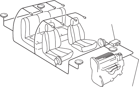
in propeller aircraft (Nelson and Elliott, 1992). The physical arrangement
of a typical feedforward active noise control system, developed in collabo-
ration with Lotus Engineering, is shown in Fig. 11.5, in which four of the
six loudspeakers, in the dashboard and front doors, were adjusted at the
engine fi ring frequency and its harmonics, to control the sum of the mean
Adaptive noise
control computer
Engine speed
signal
11.5 The components of an active noise control system for engine
noise, showing the feedforward controller deriving a reference signal
from the engine and driving four loudspeakers at a number of engine
orders, adjusted in amplitude and phase to minimise the sum of the
mean-square responses at eight microphones, positioned in the roof
lining.
Copyrighted Material downloaded from Woodhead Publishing Online
Delivered by http://woodhead.metapress.com
ETH Zuerich (307-97-768)
Sunday, August 28, 2011 12:07:04 AM
IP Address: 129.132.208.2
244 Vehicle noise and vibration refi nement
© Woodhead Publishing Limited, 2010
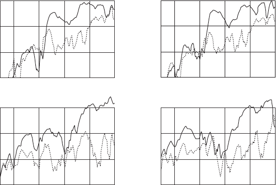
square pressures at eight microphones, mounted in the head lining. The
A-weighted sound pressure levels at the engine fi ring frequency (second
order for this 1.1-litre four-cylinder car) are shown in Fig. 11.6, measured
at the front seat positions using monitoring microphones separate from the
error microphones used by the control system. Reductions of about 10 dB
are measured in the front seats above about 3000 rpm (a fi ring frequency
of 100 Hz), which gave an improvement in the overall dB(A) level of 4 to
5 dB(A). Reductions at lower speeds were measured in the rear due to the
suppression of the fi rst longitudinal acoustic mode, which has a nodal line
near the front passengers’ heads. Nissan fi rst put such a system into produc-
tion on a Bluebird vehicle in 1992 (Hasegawa et al., 1992), in a system which
used loudspeakers, amplifi ers and processors separate from the audio
system, and so was relatively expensive.
Demonstration systems were also developed for the active control of
random road noise using feedforward techniques, with reference signals
derived from accelerometers on the vehicle suspension and body (Sutton
et al., 1994; Bernhard, 1995; Dehandschutter and Sas, 1998; Mackay and
Kenchington, 2004). In order to obtain reasonable levels of active control,
however, it was found that about six such reference signals were required.
This is because the tyre vibration is relatively uncorrelated in its various
Front left seat position
2000 3000 4000 5000 6000
80
70
60
50
Front right seat position
Rear right seat position
L
p
at engine firing frequency (dB(A))
L
p
at engine firing frequency (dB(A))
Rear left seat position
2000 3000 4000
Engine speed (rpm) Engine speed (rpm)
5000 6000
80
70
60
50
2000 3000 4000 5000 6000
80
70
60
50
2000 3000 4000 5000 6000
80
70
60
50
11.6 A-weighted engine second-order levels at the four seat positions
as a function of engine speed as a small, four-cylinder car is
accelerated along a track, without (dashed) and with (solid) the active
control system shown in Fig. 11.5 operations.
Copyrighted Material downloaded from Woodhead Publishing Online
Delivered by http://woodhead.metapress.com
ETH Zuerich (307-97-768)
Sunday, August 28, 2011 12:07:04 AM
IP Address: 129.132.208.2