Wang X. Vehicle Noise and Vibration Refinement
Подождите немного. Документ загружается.

Mid- and high-frequency problems in vehicle noise 173
© Woodhead Publishing Limited, 2010
5. Langley, R.S. and Cordioli, J.A. (2009), Hybrid deterministic–statistical analysis
of vibro-acoustic systems with domain couplings on statistical components, J.
Sound and Vibration, 321(3–5), 893–912.
6. Langley, R.S. (2008), Recent advances and remaining challenges in the statisti-
cal energy analysis of dynamic systems, 7th European Conference on Structural
Dynamics, Southampton, 7–9 July 2008.
7. Langley, R.S. and Cotoni, V. (2004), Response variance prediction in the sta-
tistical energy analysis of built-up systems, J. Acoustical Society of America,
115(2), 706–718.
8. Langley, R.S. and Bercin, A.N. (1997), Wave intensity analysis of high fre-
quency vibrations, in Statistical Energy Analysis – an Overview, with Applications
in Structural Dynamics, edited by Keane, A.J. and Price, W.G., Cambridge
University Press, Cambridge and New York.
9. Norton, M.P. (1989), Fundamentals of Noise and Vibration Analysis for
Engineers, Cambridge University Press, Cambridge and New York.
10. Cremer, L., Heckl, M. and Ungar, E.E. (1990), Structure Borne Sound: Structural
Vibrations and Sound Radiation at Audio Frequencies, 2nd edn, Springer-
Verlag, Berlin.
Copyrighted Material downloaded from Woodhead Publishing Online
Delivered by http://woodhead.metapress.com
ETH Zuerich (307-97-768)
Sunday, August 28, 2011 12:01:08 AM
IP Address: 129.132.208.2

© Woodhead Publishing Limited, 2010
174
8
Advanced simulation techniques in vehicle
noise and vibration refi nement
N. HAMPL, Ford-Werke GmbH, Germany
Abstract: Application of computer aided engineering (CAE) techniques
is a key element of contemporary vehicle development processes.
Upfront CAE simulations of vehicle noise and vibration performance
are required to select designs that meet vehicle attribute targets. CAE is
a key enabler to meet program timing and program cost by design
selection right the fi rst time before hardware and prototypes are
available.
A wide variety of CAE-tools and analytical methods is available on
the market to simulate certain aspects of noise and vibration refi nement.
Key CAE methods like fi nite element (FE), boundary element (BE),
multi-body dynamics, computational fl uid dynamics (CFD), statistical
energy analysis (SEA) and transfer path analysis (TPA) are covered in
this chapter as well as details on application and deliverables of these
tools during the virtual series process. This chapter also includes
contemporary applications like x-functional optimization and
auralization and a list of links to standard tools used by the author’s
organization.
Key words: computer aided engineering (CAE), simulation, analytical
methods, fi nite elements (FE), boundary element method (BEM),
multi-body dynamics, statistical energy analysis (SEA), computational
fl uid dynamics (CFD), transfer path analysis (TPA), virtual series,
X-functional optimization, design of experiment (DOE), visualization,
auralization.
8.1 Introduction
Application of computer aided engineering (CAE) techniques is a manda-
tory element of contemporary vehicle development processes. It is well
known to the public that several simulation loops of virtual crash tests are
performed before building and crashing a fi rst hardware prototype. Even
if prototypes can still be fully used after noise and vibration testing, upfront
CAE simulations of components as well as full vehicle noise and vibration
performance are required to ‘do it right the fi rst time’, i.e. select design
concepts capable of meeting required component and full vehicle noise and
vibration performance targets to avoid manufacturing, testing and redesign
of sub-optimal vehicles or components, for the following reasons:
Copyrighted Material downloaded from Woodhead Publishing Online
Delivered by http://woodhead.metapress.com
ETH Zuerich (307-97-768)
Sunday, August 28, 2011 12:05:48 AM
IP Address: 129.132.208.2
Advanced simulation techniques in vehicle noise 175
© Woodhead Publishing Limited, 2010
• The prototype build process is time- and resource-consuming and hence
cannot be done repeatedly during the vehicle development process;
current market constraints require short and effi cient development
processes to achieve affordable product prices.
• The fi rst ‘fully representative’ hardware prototypes are available quite
late in the development process; late design changes due to late indica-
tion of these prototypes for not meeting main attribute requirements
would jeopardize program cost and timing.
Hence, early attribute predications are essential well before availability of
the fi rst hardware prototypes; in particular, all aspects that cannot be
covered by engineering judgement or design guidelines need to be sup-
ported by CAE simulations.
Noise and vibration refi nement covers many different aspects; therefore
a wide variety of CAE tools and methods is available on the market to
simulate certain aspects of noise and vibration refi nement by analytical
methods.
Confi dence in CAE predictions for noise and vibration depends highly
on the level of modelling details; neither is there one single CAE tool in
place that can effi ciently simulate all noise and vibration effects with high
accuracy nor can a single metric express noise and vibration prediction
capabilities.
8.2 Basic simulation techniques
A high-level overview on the most important CAE methods in use for noise
and vibration refi nement is given in the following.
8.2.1 Finite element-based techniques
Finite element (FE) methods are computational methods to simulate struc-
tural performance by use of numerical models. The basic concept of all FE
techniques is to represent the geometry of each single component by a set
of numerous small-sized elements (fi nite elements) for which well-known
structural performance parameters such as stress, strain, temperature, etc.,
can be described by analytical (not necessarily linear) formulas [1, 2]. These
elements can be simple spring elements, ‘Euler–Timoshenko’ beams, shell
elements of triangular or quadrangular size, volume elements like tetrahe-
drons or hexahedrons, concentrated mass points (lumped masses), etc.
Several so-called ‘meshing’ tools are available on the market to generate
the respective FE models based on CAD geometry. Strictly speaking, the
structural performance of each of these fi nite elements can be described by
Copyrighted Material downloaded from Woodhead Publishing Online
Delivered by http://woodhead.metapress.com
ETH Zuerich (307-97-768)
Sunday, August 28, 2011 12:05:48 AM
IP Address: 129.132.208.2
176 Vehicle noise and vibration refi nement
© Woodhead Publishing Limited, 2010
the dynamic equation consisting of the element mass matrix, the element
stiffness matrix and the ‘response’ vector.
The overall mass and stiffness matrix as well as the overall response
vector are created from the respective individual matrices taking into con-
sideration connections between individual elements as well as boundary
conditions. Contemporary computer systems – from high-power computer
clusters down to single desktop PCs – are capable of effectively solving
these multi-degree-of-freedom equations and of generating requested
structural results.
The full vehicle noise and vibration FE model consists of several com-
ponent FE models, mainly of the following:
• Trimmed body FE model
• (Interior) cavity models
• Fluid–structure boundaries
• Chassis models
• Powertrain model
• Bushing and connections.
The trimmed body itself usually consists of the body in prime (i.e. all body
sheet metal with primer and all fi xed glazing; this model is created from
shell elements and connections representing spot welds, seam welds or
bonding), closures, interior trim (e.g. sound package material), instrument
panel, seats, and many further parts rigidly mounted to the body structure.
The latter can be represented with differing degrees of accuracy from
simple concentrated masses to a detailed FE model, depending on the
respective CAE task.
Cavity models represent air inside the passenger cabin, in the trunk
(boot) and for dedicated under-hood (bonnet) noise analyses, even air in
the engine bay. It is obvious that modelling of the boundary conditions for
the engine bay cavity is non-trivial and requires correlation exercises ahead
of any noise and vibration prediction.
Fluid–structure coupling describes the interrelationship between ‘sheet
metal vibration’ and in-cabin sound pressure. These fl uid–structure interac-
tions need to be capable not only of generating sound pressure due to
boundary structural vibrations, but also, vice versa, of generating structural
vibrations due to sound pressure excitation. State-of-the-art tools are well
capable of meeting these requirements with limited modelling and compu-
tational efforts.
Chassis noise and vibration models (e.g. suspension cross-members, lon-
gitudinal and lateral suspension links, anti-roll bar, twist beam rear axle,
knuckle) can be easily derived from the respective CAE models for strength
and durability analyses. Even though non-linear FE models are normally
used to analyse strain effects and plastic deformation under extreme load-
Copyrighted Material downloaded from Woodhead Publishing Online
Delivered by http://woodhead.metapress.com
ETH Zuerich (307-97-768)
Sunday, August 28, 2011 12:05:48 AM
IP Address: 129.132.208.2
Advanced simulation techniques in vehicle noise 177
© Woodhead Publishing Limited, 2010
ings for the latter, linear models can well be used for noise and vibration
analyses as even extreme noise loads should never cause any plastic defor-
mation of any load-carrying structure.
Powertrain FE models for application to vehicle noise and vibration
refi nement represent the engine (this model consists predominantly of
solids) and transmission as well as drive shafts. Further FE models repre-
sent the exhaust, intake, accessory drive, powertrain mounts, etc. It needs
to be noted that real-world operational temperatures need to be taken into
account, in particular for exhausts, to correctly represent actual structural
performance.
All these individual FE models need to be combined into one single FE
model. As almost all currently used FE tools are based on unique ‘grid’
numbers for each node of uniquely numbered elements, using uniquely
assigned material numbers to defi ne material properties, each number must
be used just once per category. Sophisticated internal numbering conven-
tions or effi cient renumbering mechanisms need to be applied for assembly
of a full vehicle FE model to avoid any grid, element or material number
duplication which would jeopardize the CAE model. Unlike in the early
stages of FE analyses, grid numbers no longer need to be manually allo-
cated to achieve best ‘narrowband’ system matrices for effi cient solution,
as up-to-date FE solvers do an internal reordering of system equations
anyhow to achieve best computational performance.
The main task for full vehicle analyses is to predict customer perceptions
of noise and vibration and to understand overall vehicle behaviour rather
than doing detailed subsystem optimizations (e.g. panel thickness, topology
optimization, etc.). Hence effi cient full vehicle analyses can be achieved
using ‘superelement’ techniques [3] by substructuring the vehicle FE model
into individual pieces (e.g. body structure, closures, suspension compo-
nents, etc.). Each superelement is processed individually at defi ned bound-
ary conditions; the solutions are then combined to solve the entire model.
The fi nal analysis (in which all of the individual superelement solutions are
combined) involves much smaller matrices than would be required to solve
the entire model in a single solution. This technique has the advantage of
reducing computer resource requirements, especially if changes are made
to just one component (superelement) of the vehicle; in this case, only the
affected superelement needs to be reanalysed and the fi nal analysis repeated.
For standard superelement analysis each piece is represented by a
reduced stiffness, mass and damping matrix, including all connection nodes
and analysis points, whereas component mode synthesis is a form of super-
element dynamic reduction wherein matrices are defi ned in terms of modal
coordinates (corresponding to the superelement modes) and physical coor-
dinates (corresponding to the grid points on the superelement boundaries).
The advantage of component modal synthesis is the signifi cantly smaller
Copyrighted Material downloaded from Woodhead Publishing Online
Delivered by http://woodhead.metapress.com
ETH Zuerich (307-97-768)
Sunday, August 28, 2011 12:05:48 AM
IP Address: 129.132.208.2
178 Vehicle noise and vibration refi nement
© Woodhead Publishing Limited, 2010
number of modal coordinates compared to the number of physical coordi-
nates of the detailed model. It should be noted that each superelement
could be derived also from physical testing, thereby increasing the accuracy
of the overall analysis.
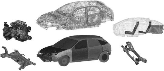
A display model for a full vehicle noise and vibration analysis and its
components is shown in Fig. 8.1.
8.2.2 Boundary element-based techniques
The boundary element method (BEM) is an alternative numerical approach
to solve linear partial differential equations if these can be formulated as
integral equations (i.e. in boundary integral form) [4]. The main application
fi eld for BEM in vehicle noise and vibration refi nement is sound radiation
simulation of engine, exhaust shell, etc.
The boundary element method attempts to use given boundary condi-
tions to fi t boundary values rather than values throughout the space defi ned
by a partial differential equation. Once this is done the integral equation
can be used in the post-processing stage to numerically calculate the solu-
tion at any desired point in the solution domain. The boundary element
method is often more effi cient than other methods, including fi nite ele-
ments, in terms of computational resources for problems where there is a
small surface to volume ratio.
For BE models, unlike FE models, the boundary surface is modelled by
surface elements instead of the continuum (e.g. interior cavity of a vehicle,
or environment around an engine). FE results as well as test results (e.g.
vibration velocity of a powertrain surface) can be used to defi ne boundary
conditions.
8.1 Finite-element-based full vehicle noise and vibration CAE model of
a Ford Focus and its main superelements: trimmed body, interior
cavities, rear and front suspension subframes, powertrain.
Copyrighted Material downloaded from Woodhead Publishing Online
Delivered by http://woodhead.metapress.com
ETH Zuerich (307-97-768)
Sunday, August 28, 2011 12:05:48 AM
IP Address: 129.132.208.2
Advanced simulation techniques in vehicle noise 179
© Woodhead Publishing Limited, 2010
8.2.3 Multi-body dynamics
Multi-body dynamics tools are well established for simulation of structures
and mechanisms characterized by geometric non-linearity, large defl ec-
tions, backlash, etc. [5]. These tools offer a variety of predefi ned compo-
nents, linear as well as non-linear connections, etc. The equations of motion
for these systems can only be solved in the time domain. Small time steps
are required to correctly cover dynamical effects; selection of proper
numerical solvers and time increments is mandatory to effi ciently derive
correct results. To keep computational efforts small, structural elements for
multi-body models are usually represented by signifi cantly simpler ele-
ments than detailed FE component models. Nevertheless, some of these
tools are nowadays capable of including subsystem FE models; both model
assembly and computational effort are signifi cantly increased for such
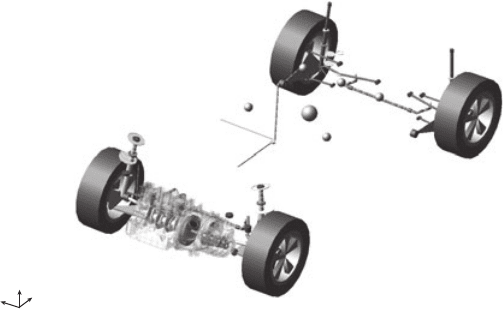
approaches. Figure 8.2 shows a Ford Focus multi-body CAE model.
In addition to structural systems, some multi-body systems offer inter-
faces to software packages capable of simulating system dynamics and
control strategies.
8.2.4 Tools for system dynamics
Another category of simulation tools use dedicated mathematical and
logical models to defi ne system dynamics of the individual (not necessarily
structural) vehicle components [6]. Hence, even dynamic control algorithms
can be included in this type of CAE model. A typical application for noise
and vibration refi nement is upfront simulation of noise attenuation systems
y
z
x
8.2 Multi-body CAE model of Ford Focus to simulate start/stop
vibrations. Suspension is represented by bars and bushes; detailed
model of crank train; trimmed body represented by concentrated
mass.
Copyrighted Material downloaded from Woodhead Publishing Online
Delivered by http://woodhead.metapress.com
ETH Zuerich (307-97-768)
Sunday, August 28, 2011 12:05:48 AM
IP Address: 129.132.208.2
180 Vehicle noise and vibration refi nement
© Woodhead Publishing Limited, 2010
as well as active nibble cancellation tools included in electrical power-
assisted steering (EPAS). Libraries of predefi ned dynamical elements are
offered within these toolsets to help users set up new models with minimum
effort for developing new system dynamics equations.
8.2.5 Statistical energy analysis methods
Application of the above simulation tools is restricted to frequency ranges
where ‘exact’ dynamic equations can be set up. This is not necessarily the
case for mid- to high-frequency noise – for vehicle noise and vibration
refi nement the lower bound of this frequency range is between 250 and
400 Hz. Statistical approaches such as the so-called Statistical Energy
Analysis (SEA) method need to be applied for these types of noise simula-
tion and prediction [7, 8]. The basic principle of SEA is to solve equations
for energy balance between individual sub-structures. Consequently, a
vehicle needs to be partitioned into sub-structures that can be described by
their acoustical or vibration energy within their boundaries, power source
or energy loss within their boundaries and energy fl ow to all neighbouring
sub-structures.
Each SEA tool includes libraries of energy equations for different
element types; these are derived from FE analyses and correlation tests as
well as assumptions for coupling loss factors. Extensive upfront correlation
exercises are required until predictions can be made for road noise as well
as wind noise. SEA techniques are well established for optimizing sound
packages as these predict interior noise changes due to thickness or mate-
rial changes of sound package material.
8.2.6 Computational fl uid dynamics (CFD)
Tools for computational fl uid dynamics (CFD) are required to simulate and
predict aerodynamic and aeroacoustic vehicle phenomena. All CFD tools
use numerical methods and algorithms to solve partial differential equa-
tions to analyse problems that involve fl uid fl ows as well as interaction of
gases with surfaces defi ned by boundary conditions.
The traditional approach in CFD in automotive engineering is to start
with the Navier–Stokes (N–S) equations which statistically describe a real
fl uid [9]. The problem is that for most cases of interest, the solutions to
these very complex and highly non-linear equations are characterized by
many degrees of freedom, thus requiring a high computational effort.
An alternative approach is to use the Lattice Boltzmann method (LBM)
which is a special discretization of the continuum Boltzmann equation in
space, time and velocity. Conceptually, LBM recovers hydrodynamics
by formulating a conservation theorem for any quantity conserved during
Copyrighted Material downloaded from Woodhead Publishing Online
Delivered by http://woodhead.metapress.com
ETH Zuerich (307-97-768)
Sunday, August 28, 2011 12:05:48 AM
IP Address: 129.132.208.2
Advanced simulation techniques in vehicle noise 181
© Woodhead Publishing Limited, 2010
collisions of particles. Mass, momentum and energy are each specifi ed in
this theorem, generating three equations, recovering compressible mass
continuity, a momentum equation and an energy equation [10].
All CFD analyses are normally performed by aerodynamics specialists.
They can do all the postprocessing to derive acoustic excitation for noise
refi nement analyses from regular CFD analyses with just minor enhance-
ments to fulfi l aeroacoustic needs. Taking into account the main frequency
as well as the structure of wind noise, it is straightforward to use SEA tools
to predict wind noise based on CFD excitation data.
8.2.7 Transfer path analyses (TPA)
An entirely different analysis concept is used for transfer path analysis
(TPA). For any TPA a vehicle is characterized by its ‘noise paths’ rather
than by actual geometry. The principal concept of TPA is to sum up all
individual noise paths (individual noise sources multiplied by respective
noise sensitivity) to the full vehicle noise or vibration response. Individual
noise sources are typically mount forces, intake and exhaust orifi ce noise,
powertrain noise radiation, high-frequency noise, under-hood sound due to
powertrain rigid body motion, etc. For the example of a powertrain mount,
the respective noise source would be mount displacement multiplied by
mount stiffness; the respective noise sensitivity would be p/F (sound pres-
sure (p) per unit excitation force (F)) and noise transfer function (NTF).
The mathematical effort for TPA methods itself is signifi cantly lower
than for FE or BE methods, but valid TPA models require representative
data for, e.g., noise sensitivities. If the latter cannot be predicted with high
confi dence, these need to be based on measured noise sensitivities. Hence
these methods will be ‘exact’ only for installations of ‘new’ powertrains into
given structures. Noise sources can be based on measurements or CAE
analyses.
8.3 Frequency or time-domain methods
The majority of FEM and BEM analyses for noise and vibration refi nement
are performed in the frequency domain rather than in the time domain by
applying modal frequency response analyses. This approach signifi cantly
reduces CPU time, but should be applied only for quasi-stationary phenom-
ena like idle, cruising road and wind noise, slow speed changes during
acceleration or overrun, as well as for calculating transfer functions.
Time-domain analyses are appropriate for non-linear structures as well
as for non-periodic load cases. Typical time-domain analyses cover simula-
tion of non-linear systems and materials as well as single impacts, key-on/
key-off simulations, brake judder responses, etc. Time increments for any
Copyrighted Material downloaded from Woodhead Publishing Online
Delivered by http://woodhead.metapress.com
ETH Zuerich (307-97-768)
Sunday, August 28, 2011 12:05:48 AM
IP Address: 129.132.208.2
182 Vehicle noise and vibration refi nement
© Woodhead Publishing Limited, 2010
time-domain analysis need to be small enough to ensure two simulation
instances within one complete vibration cycle of the system with highest
system eigenfrequency.
8.4 Simulation process
Simulation processes occur in three distinct phases during vehicle
development:
1. Early concept selection using simplifi ed (concept) models – these analy-
ses are normally done individually for each attribute, and common
concepts need to be agreed before detailed component design starts.
2. Virtual verifi cation and x-functional optimization of x-attribute agreed
‘frozen’ design – virtual series.
3. Support of actual attribute issues on ‘verifi cation prototypes’ and cor-
relation of CAE models.
8.4.1 Virtual series
Once design has achieved a maturity level that allows creation of simulation
models for all individual attributes, a so-called ‘CAD freeze’ will kick-off
a ‘virtual series’ process. The main concept of virtual series is that early
assessments for all attributes and teams need to be based on one common
design well before the fi rst hardware prototypes are created for the fi nal
engineering ‘sign-off’. Virtual series are by no means restricted just to
typical CAE attributes like safety, durability, noise, cooling, etc., but are
also applied to analyses on cost, weight, manufacturing, etc.
Once the design is frozen, all component areas, including their suppliers,
will start ‘meshing’ components they are responsible for. These meshes can
still be attribute-independent, i.e. can be used for both safety (high defor-
mation requiring non-linear material laws) as well as noise calculations
(small deformations within linearity range).
Each attribute CAE team will then incorporate these FE meshes as well
as supplier models into attribute-specifi c simulation models. Model cre-
ation typically consists of 70% chasing for data (e.g. actual dynamic mount
stiffness under operational load; mass, centre of gravity and moment of
inertia for all parts for which no FE mesh is required or available) and 30%
modelling and analysis.
All simulation results need to be jointly reviewed to agree on corrective
actions (these may be based on dedicated model modifi cations) and to
incorporate these changes into CAD design for the next ‘virtual series
freeze’. The timespan between CAD freeze and reporting on the vehicle
noise and vibration refi nement results is typically in the order of 6–10
Copyrighted Material downloaded from Woodhead Publishing Online
Delivered by http://woodhead.metapress.com
ETH Zuerich (307-97-768)
Sunday, August 28, 2011 12:05:48 AM
IP Address: 129.132.208.2