Tsoulfanidis N. Measurement and detection of radiation
Подождите немного. Документ загружается.

178
MEASUREMENT AND DETECTlON OF RADIATION
I
Detector
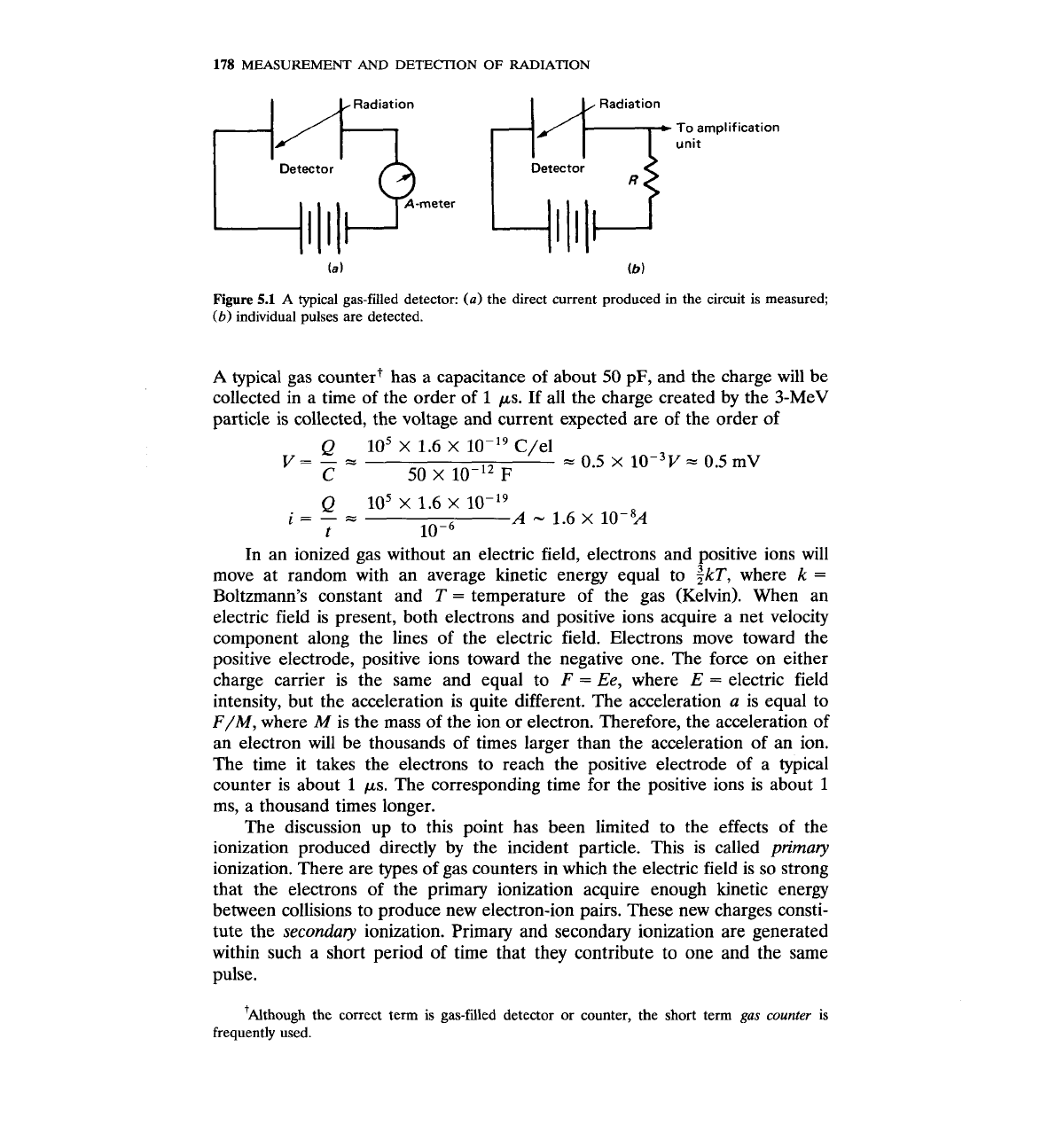
Figure 5.1
A
typical gas-filled detector:
(a)
the direct current produced in the circuit is measured;
(b)
individual pulses are detected.
A
typical gas countert has a capacitance of about
50
pF, and the charge will be
collected in a time of the order of
1
ps. If all the charge created by the 3-MeV
particle is collected, the voltage and current expected are of the order of
In an ionized gas without an electric field, electrons and positive ions will
move at random with an average kinetic energy equal to $k~, where
k
=
Boltzmann's constant and T
=
temperature of the gas (Kelvin). When an
electric field is present, both electrons and positive ions acquire a net velocity
component along the lines of the electric field. Electrons move toward the
positive electrode, positive ions toward the negative one. The force on either
charge carrier is the same and equal to
F
=
Ee,
where
E
=
electric field
intensity, but the acceleration is quite different. The acceleration
a
is equal to
F/M, where M is the mass of the ion or electron. Therefore, the acceleration of
an electron will be thousands of times larger than the acceleration of an ion.
The time it takes the electrons to reach the positive electrode of a typical
counter is about
1
ps. The corresponding time for the positive ions is about
1
ms, a thousand times longer.
The discussion up to this point has been limited to the effects of the
ionization produced directly by the incident particle. This is called primary
ionization. There are types of gas counters in which the electric field is so strong
that the electrons of the primary ionization acquire enough kinetic energy
between collisions to produce new electron-ion pairs. These new charges consti-
tute the
secondary
ionization. Primary and secondary ionization are generated
within such a short period of time that they contribute to one and the same
'~lthou~h the correct term is gas-filed detector or counter, the short term
gas
counter
is
frequently used.
GAS-FILLED
DETECTORS
179
5.2
RELATIONSHIP
BETWEEN
HIGH VOLTAGE
AND
CHARGE COLLECTED
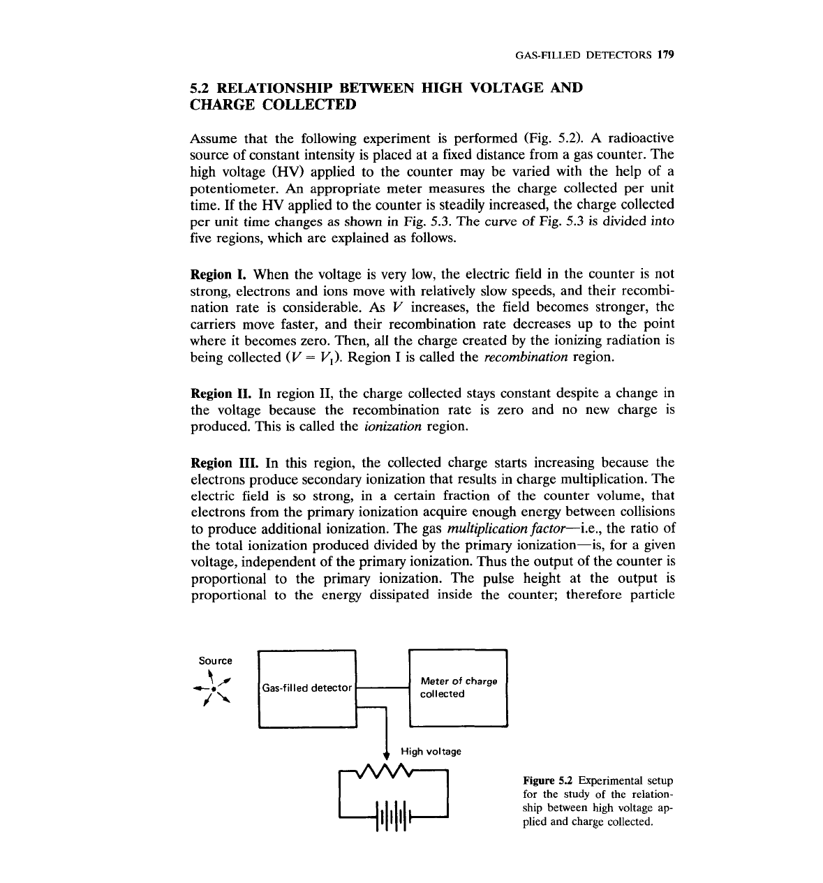
Assume that the following experiment is performed (Fig.
5.2).
A
radioactive
source of constant intensity is placed at a fixed distance from a gas counter. The
high voltage (HV) applied to the counter may be varied with the help of a
potentiometer.
An
appropriate meter measures the charge collected per unit
time. If the HV applied to the counter is steadily increased, the charge collected
per unit time changes as shown in Fig.
5.3.
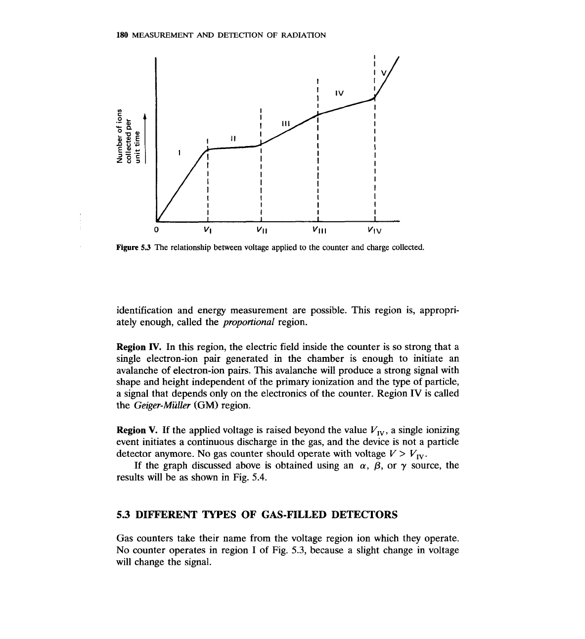
The curve of Fig.
5.3
is divided into
five regions, which are explained as follows.
Region
1.
When the voltage is very low, the electric field in the counter is not
strong, electrons and ions move with relatively slow speeds, and their recombi-
nation rate is considerable. As
V
increases, the field becomes stronger, the
carriers move faster, and their recombination rate decreases up to the point
where it becomes zero. Then, all the charge created by the ionizing radiation is
being collected
(V
=
VI).
Region I is called the recombination region.
Region
11.
In region 11, the charge collected stays constant despite a change in
the voltage because the recombination rate is zero and no new charge is
produced. This is called the ionization region.
Region
111.
In this region, the collected charge starts increasing because the
electrons produce secondary ionization that results in charge multiplication. The
electric field is so strong, in a certain fraction of the counter volume, that
electrons from the primary ionization acquire enough energy between collisions
to produce additional ionization. The gas multiplication factorpie., the ratio of
the total ionization produced divided by the primary ionization-is, for a given
voltage, independent of the primary ionization. Thus the output of the counter is
proportional to the primary ionization. The pulse height at the output is
proportional to the energy dissipated inside the counter; therefore particle
Source
Meter of charge
collected
4
High voltage
Figure
5.2
Experimental setup
for the study
of
the relation-
ship between
high
voltage ap-
plied and charge collected.
180
MEASUREMENT
AND
DETECTION
OF
RADIATION
0
"I
"I
I
"lll
"I
v
Figure
5.3
The relationship between voltage applied to the counter and charge collected.
identification and energy measurement are possible. This region is, appropri-
ately enough, called the
proportional
region.
Region
IV.
In this region, the electric field inside the counter is so strong that a
single electron-ion pair generated in the chamber is enough to initiate an
avalanche of electron-ion pairs. This avalanche will produce a strong signal with
shape and height independent of the primary ionization and the type of particle,
a signal that depends only on the electronics of the counter. Region IV is called
the
Geiger-Muller
(GM)
region.
Region
V.
If the applied voltage is raised beyond the value VIv, a single ionizing
event initiates a continuous discharge in the gas, and the device is not a particle
detector anymore. No gas counter should operate with voltage
V
>
VIv.
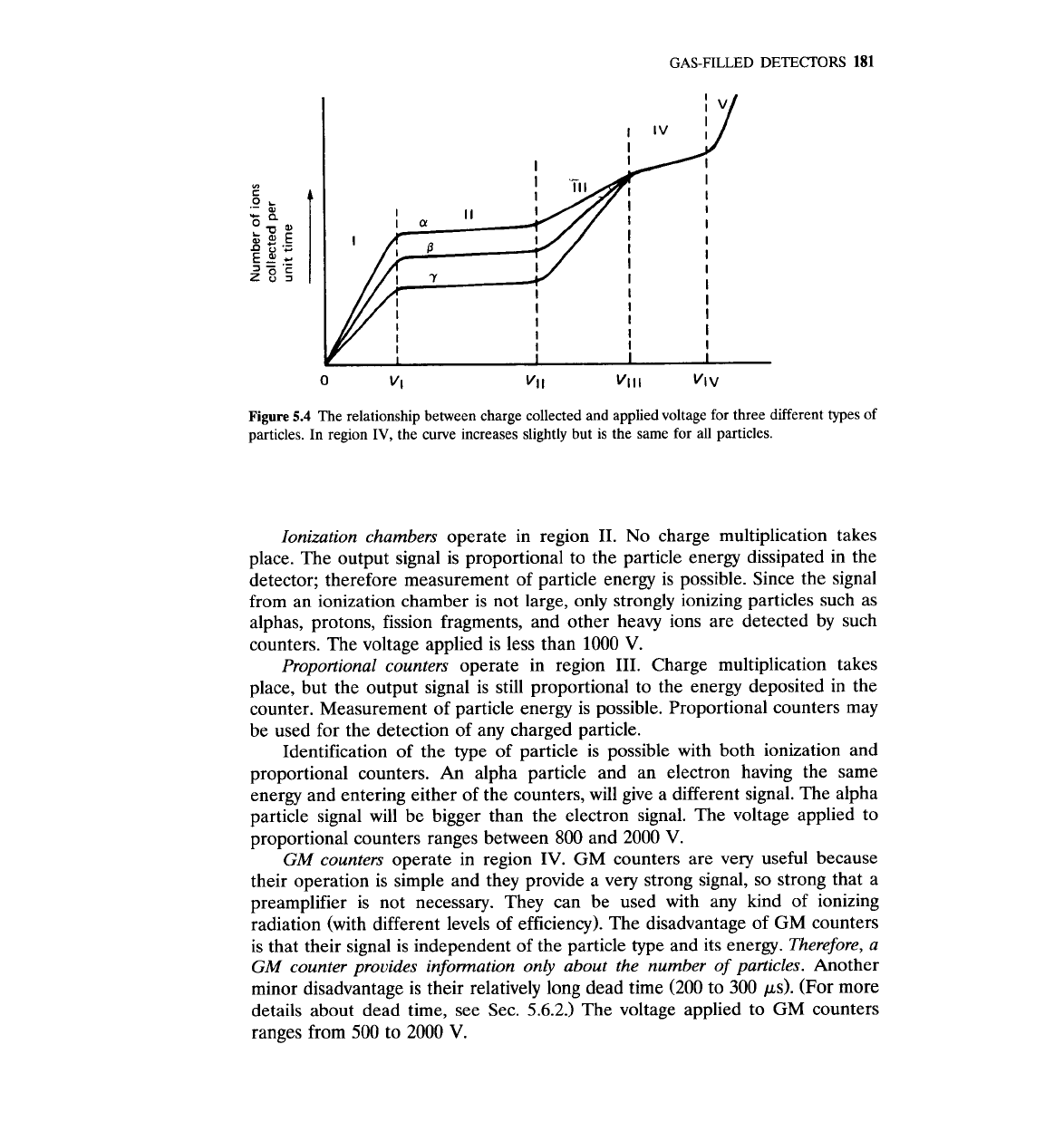
If the graph discussed above is obtained using an
a,
j3,
or
y
source, the
results will be as shown in Fig.
5.4.
5.3
DIF'F'ERENT TYPES OF GAS-FILLED DETECTORS
Gas counters take their name from the voltage region ion which they operate.
No counter operates in region I of Fig.
5.3,
because a slight change in voltage
will change the signal.
GAS-FILLED
DETECTORS
181
Figure
5.4
The relationship between charge collected and applied voltage for three different types of
particles. In region
IV,
the curve increases slightly but is the same for all particles.
Ionization chambers
operate in region 11. No charge multiplication takes
place. The output signal is proportional to the particle energy dissipated in the
detector; therefore measurement of particle energy is possible. Since the signal
from an ionization chamber is not large, only strongly ionizing particles such as
alphas, protons, fission fragments, and other heavy ions are detected by such
counters. The voltage applied is less than
1000
V.
Proportional counters
operate in region 111. Charge multiplication takes
place, but the output signal is still proportional to the energy deposited in the
counter. Measurement of particle energy is possible. Proportional counters may
be used for the detection of any charged particle.
Identification of the type of particle is possible with both ionization and
proportional counters.
An
alpha particle and an electron having the same
energy and entering either of the counters, will give a different signal. The alpha
particle signal will be bigger than the electron signal. The voltage applied to
proportional counters ranges between 800 and 2000
V.
GM
counters
operate in region
IV.
GM
counters are very useful because
their operation is simple and they provide a very strong signal, so strong that a
preamplifier is not necessary. They can be used with any kind of ionizing
radiation (with different levels of efficiency). The disadvantage of
GM
counters
is that their signal is independent of the particle type and its energy.
Therefore, a
GM
counter provides information only about the number of particles.
Another
minor disadvantage is their relatively long dead time (200 to 300 ps). (For more
details about dead time, see
Sec.
5.6.2.)
The voltage applied to GM counters
ranges from 500 to 2000
V.
182
MEASUREMENT
AND
DETECTION OF RADIATION
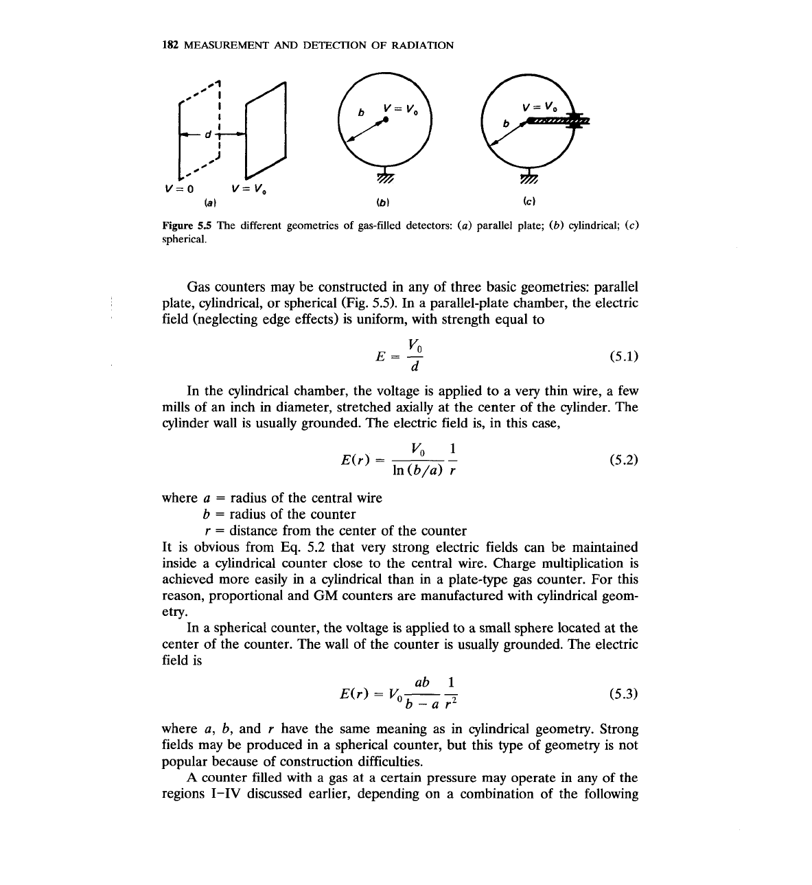
Figure
5.5
The different geometries
of
gas-filled detectors:
(a)
parallel plate;
(b)
cylindrical;
(c)
spherical.
Gas counters may be constructed in any of three basic geometries: parallel
plate, cylindrical, or spherical (Fig.
5.5).
In a parallel-plate chamber, the electric
field (neglecting edge effects) is uniform, with strength equal to
In the cylindrical chamber, the voltage is applied to a very thin wire, a few
mills of an inch in diameter, stretched axially at the center of the cylinder. The
cylinder wall is usually grounded. The electric field is, in this case,
where
a
=
radius of the central wire
b
=
radius of the counter
r
=
distance from the center of the counter
It is obvious from Eq.
5.2
that very strong electric fields can be maintained
inside a cylindrical counter close to the central wire. Charge multiplication is
achieved more easily in a cylindrical than in a plate-type gas counter. For this
reason, proportional and
GM
counters are manufactured with cylindrical geom-
etry.
In a spherical counter, the voltage is applied to a small sphere located at the
center of the counter. The wall of the counter is usually grounded. The electric
field is
where
a,
b, and
r
have the same meaning as in cylindrical geometry. Strong
fields may be produced in a spherical counter, but this type of geometry is not
popular because of construction difficulties.
A
counter filled with a gas at a certain pressure may operate in any of the
regions I-IV discussed earlier, depending on a combination of the following
GAS-FILLED
DETECTORS
183
parameters:
1.
Size of the counter
2.
Size of wire (in cylindrical counters)
3.
Gas type
4.
Gas pressure
5.
Level of high voltage
Normally, gas counters are manufactured to operate in one region only. The
user buys an ionization counter, a proportional counter, or a GM counter. The
manufacturer has selected the combination of variables
1-4
listed above that
results in the desired type of gas counter. The last variable, the high voltage
applied, is not a fixed number, but a range of values. The range is specified by
the manufacturer, but the user decides on the best possible value of
HV.
The rest of this chapter discusses the special characteristics of the three
types of gas counters.
5.4
IONIZATION CHAMBERS
5.4.1
Pulse
Formation in an Ionization Chamber
The formation and shape of the signal in an ionization chamber will be analyzed
for a parallel-plate counter as shown in Fig.
5.lb.
The analysis is similar for a
cylindrical or a spherical chamber.
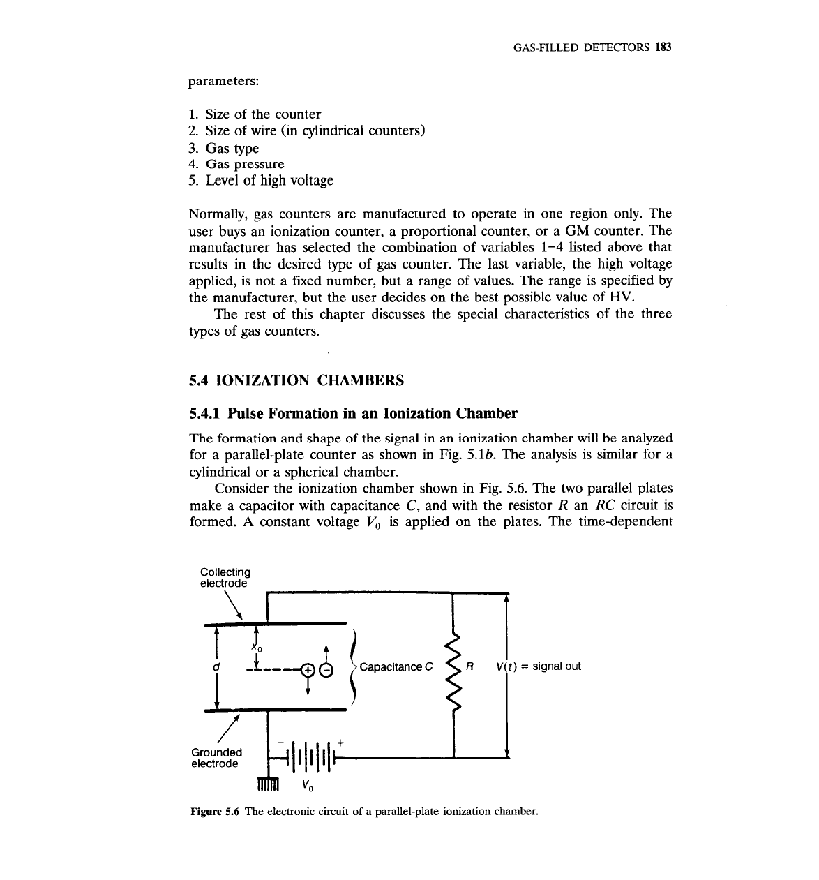
Consider the ionization chamber shown in Fig. 5.6. The two parallel plates
make a capacitor with capacitance
C,
and with the resistor
R
an
RC
circuit is
formed.
A
constant voltage
Vo
is applied on the plates. The time-dependent
Collecting
electrode
'+
1
$
I
Capacitance
C
R
V(t)
=
signal out
Grounded
electrode
Z
Figure
5.6
The electronic circuit
of
a parallel-plate ionization chamber.
184
MEASUREMENT
AND
DETECITON
OF
RADIATION
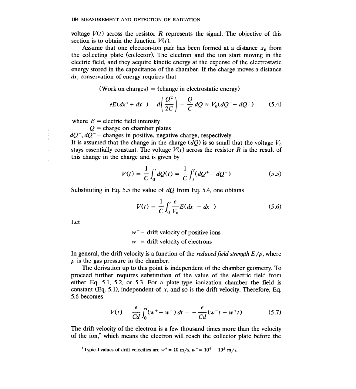
voltage V(t) across the resistor
R
represents the signal. The objective of this
section is to obtain the function V(t).
Assume that one electron-ion pair has been formed at a distance
x,
from
the collecting plate (collector). The electron and the ion start moving in the
electric field, and they acquire kinetic energy at the expense of the electrostatic
energy stored in the capacitance of the chamber. If the charge moves a distance
a!x,
conservation of energy requires that
(Work on charges)
=
(change in electrostatic energy)
where
E
=
electric field intensity
Q
=
charge on chamber plates
dQt, dQ-= changes in positive, negative charge, respectively
It is assumed that the change in the charge
(dQ) is so small that the voltage Vo
stays essentially constant. The voltage V(t) across the resistor
R
is the result of
this change in the charge and is given by
Substituting in
Eq.
5.5 the value of dQ from Eq. 5.4, one obtains
Let
w
+
=
drift velocity of positive ions
w-
=
drift velocity of electrons
In general, the drift velocity is a function of the reducedfield strength E/p, where
p
is the gas pressure in the chamber.
The derivation up to this point is independent of the chamber geometry. To
proceed further requires substitution of the value of the electric field from
either Eq. 5.1, 5.2, or 5.3. For a plate-type ionization chamber the field is
constant (Eq. 5.0, independent of
x,
and so is the drift velocity. Therefore,
Eq.
5.6 becomes
The drift velocity of the electron is a few thousand times more than the velocity
of the
ion,+ which means the electron will reach the collector plate before the
'~~~ical values
of
drift velocities are
w+=
10
m/s,
w-=
lo4
-
lo5
m/s.
GAS-FILLED
DETECTORS
185
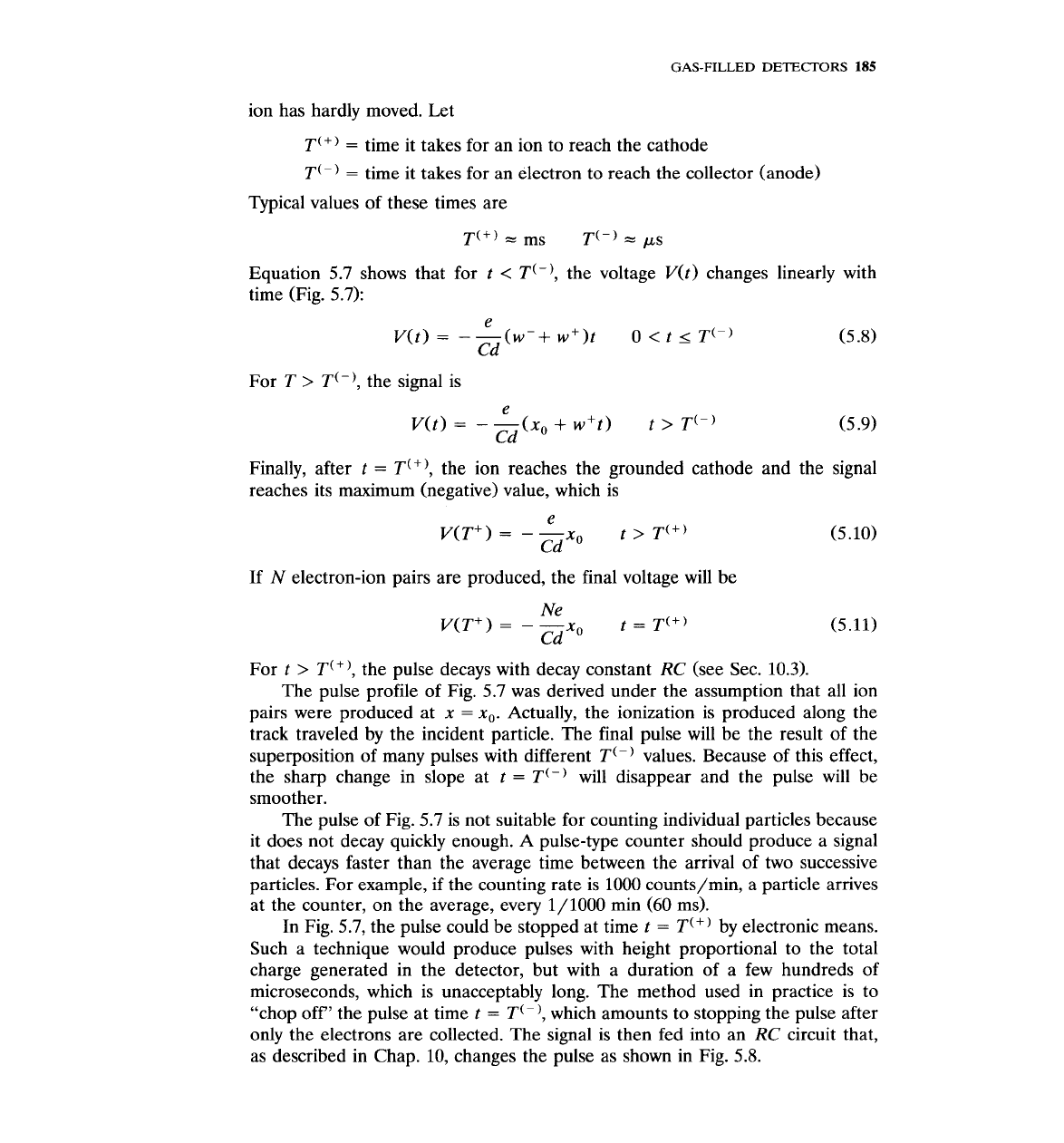
ion has hardly moved. Let
T(+)
=
time it takes for an ion to reach the cathode
T(-)
=
time it takes for an electron to reach the collector (anode)
Typical values of these times are
T(')
-
ms
T(-)
=
PS
Equation 5.7 shows that for t
<
T(-), the voltage V(t) changes linearly with
time (Fig. 5.7):
e
V(t)
=
-
-(w-+ w+)t 0
<
t
5
T"
Cd
For T
>
T(-),
the signal is
e
V(t)
=
-
-(xo
+
w't)
t
>
T(-)
Cd
Finally, after t
=
T('),
the ion reaches the grounded cathode
reaches its maximum (negative) value, which is
e
V(T+)
=
-
-x0
t
>
T'"
Cd
(5.9)
and the signal
If
N
electron-ion pairs are produced, the final voltage will be
For t
>
T(+), the pulse decays with decay constant
RC
(see Sec. 10.3).
The pulse profile of Fig. 5.7 was derived under the assumption that all ion
pairs were produced at
x
=
x,.
Actually, the ionization is produced along the
track traveled by the incident particle. The final pulse will be the result of the
superposition of many pulses with different T(-) values. Because of this effect,
the sharp change in slope at
t
=
T(-) will disappear and the pulse will be
smoother.
The pulse of Fig. 5.7 is not suitable for counting individual particles because
it does not decay quickly enough. A pulse-type counter should produce a signal
that decays faster than the average time between the arrival of two successive
particles. For example, if the counting rate is 1000
counts/min, a particle arrives
at the counter, on the average, every
1/1000 min (60 ms).
ic means.
In Fig. 5.7, the pulse could be stopped at time t
=
T(+) by electron'
Such a technique would produce pulses with height proportional to the total
charge generated in the detector, but with a duration of a few hundreds of
microseconds, which is unacceptably long. The method used in practice is to
"chop off' the pulse at time t
=
T(-), which amounts to stopping the pulse after
only the electrons are collected. The signal is then fed into an
RC
circuit that,
as described in Chap. 10, changes the pulse as shown in Fig. 5.8.
186
MEASUREMENT
AND
DETECTION
OF
RADIATION
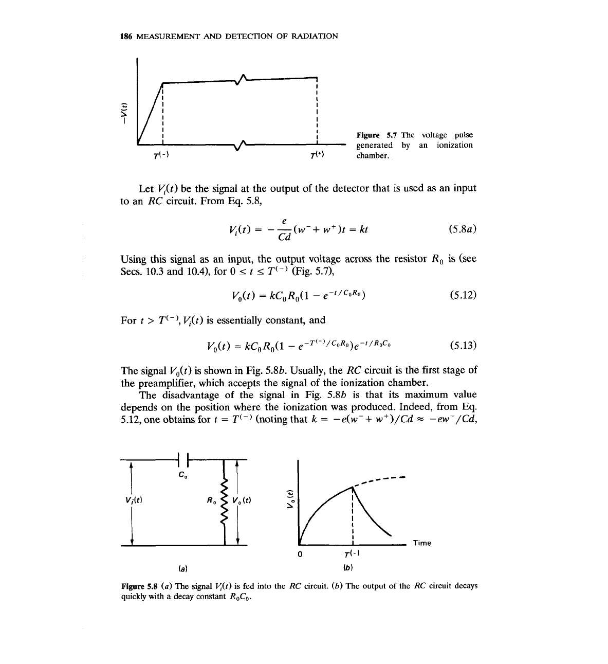
Figure
5.7
The voltage pulse
generated by an ionization
chamber.
Let y(t) be the signal at the output of the detector that is used as an input
to an RC circuit. From
Eq.
5.8,
Using this signal as an input, the output voltage across the resistor R, is (see
Secs. 10.3 and 10.4), for 0
5
t
5
T(-)
(Fig. 5.71,
For
t
>
T(-1,
K(t) is essentially constant, and
The signal V,(t) is shown in Fig. 5.8b. Usually, the RC circuit is the first stage of
the preamplifier, which accepts the signal of the ionization chamber.
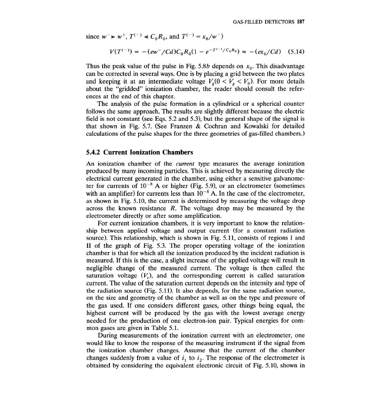
The disadvantage of the signal in Fig.
5.8b is that its maximum value
depends on the position where the ionization was produced. Indeed, from
Eq.
5.12, one obtains for
t
=
T(-)
(noting that
k
=
-e(w-
+
w +)/Cd
=
-ewP/Cd,
Figure
5.8
(a)
The signal
v(t)
is fed into the
RC
circuit.
(b)
The output of the
RC
circuit decays
quickly with a decay constant
ROCo.
GAS-FILLED DETECTORS
187
since wp* w+, T(-)
4
CORO, and
T(-)
=
xO/w-)
Thus the peak value of the pulse in Fig. 5.8b depends on
x,.
This disadvantage
can be corrected in several ways. One is by placing a grid between the two plates
and keeping it at an intermediate voltage
V,(O
<
V,
<
V,). For more details
about the "gridded" ionization chamber, the reader should consult the refer-
ences at the end of this chapter.
The analysis of the pulse formation in a cylindrical or a spherical counter
follows the same approach. The results are slightly different because the electric
field is not constant (see Eqs. 5.2 and
5.3), but the general shape of the signal is
that shown in Fig.
5.7.
(See Franzen
&
Cochran and Kowalski for detailed
calculations of the pulse shapes for the three geometries of gas-filled chambers.)
5.4.2
Current Ionization Chambers
An
ionization chamber of the
current
type measures the average ionization
produced by many incoming particles. This is achieved by measuring directly the
electrical current generated in the chamber, using either a sensitive galvanome-
ter for currents of
A
or higher (Fig. 5.9), or an electrometer (sometimes
with an amplifier) for currents less than
lo-'
A.
In the case of the electrometer,
as shown in Fig. 5.10, the current is determined by measuring the voltage drop
across the known resistance R. The voltage drop may be measured by the
electrometer directly or after some amplification.
For current ionization chambers, it is very important to know the relation-
ship between applied voltage and output current (for a constant radiation
source). This relationship, which is shown in Fig. 5.11, consists of regions
I
and
I1
of the graph of Fig.
5.3.
The proper operating voltage of the ionization
chamber is that for which all the ionization produced
by
the incident radiation is
measured. If this is the case, a slight increase of the applied voltage will result in
negligible change of the measured current. The voltage is then called the
saturation voltage
(I/,),
and the corresponding current is called saturation
current. The value of the saturation current depends on the intensity and type of
the radiation source (Fig. 5.11). It also depends, for the same radiation source,
on the size and geometry of the chamber as well as on the type and pressure of
the gas used. If one considers different gases, other things being equal, the
highest current will be produced by the gas with the lowest average energy
needed for the production of one electron-ion pair. Typical energies for com-
mon gases are given in Table 5.1.
During measurements of the ionization current with an electrometer, one
would like to know the response of the measuring instrument if the signal from
the ionization chamber changes. Assume that the current of the chamber
changes suddenly from a value of
i,
to
i,.
The response of the electrometer is
obtained by considering the equivalent electronic circuit of Fig. 5.10, shown in