Tsch?tsch H., Koth A. Metal Forming Practise: Processes - Machines - Tools
Подождите немного. Документ загружается.

16.8 Bending work W 201
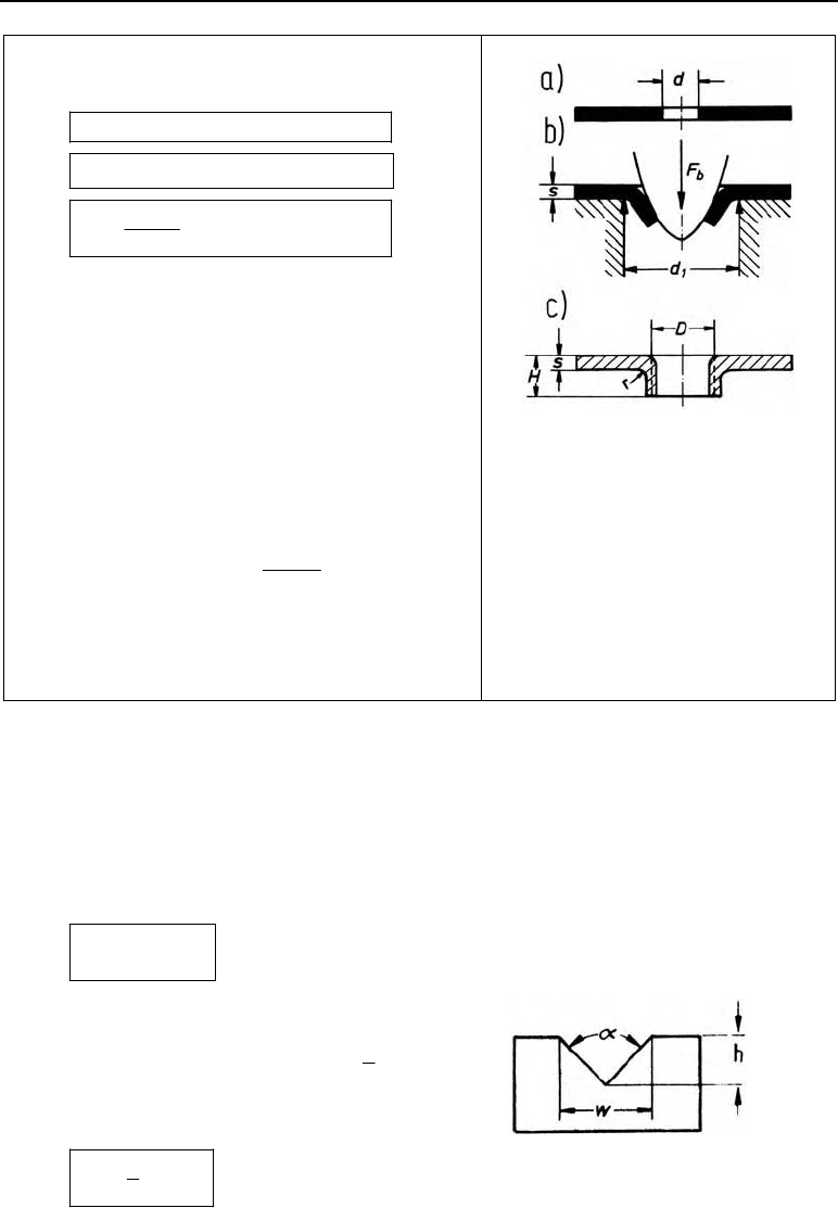
16.7.6 Collar forming
b1m
0.7 FsdR
G
2 0.43 0.72 dD H r s
0.43 0.72
2
Dd
Hrs
F
b
in N bending force
H in mm height of the collar,
H
max
| 0.12 · d
1
+ s
D in mm mean collar diameter
s in mm sheet thickness
r in mm bend radius
d
1
in mm bore diameter of the die,
d
1
| D + 0.3 · s
G
in mm hole opening value,
1
1
dd
d
G
d in mm diameter of the punched-out
hole
R
m
in N/mm
2
tensile strength
Figure 16.9 The principle of collar form-
ing,
a) workpiece before,
b) during,
c) after forming
16.8 Bending work W
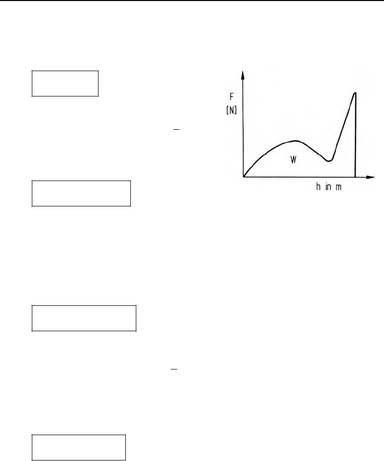
16.8.1 V-bending
b
WxFh In general
W in N m Bending work
x process factor,
1
3
x
F
b
in N bending force
h in m punch displacement
b
1
3
WFh
202 16 Bending
16.8.2 U-bending
without a spring-actuated pressure pad (no final bottoming the punch)
b
WxFh
W in N m bending work
x process factor;
2
3
x
F
b
in N bending force
h in m punch displacement;
4hs
2
m
1.06 WsbR
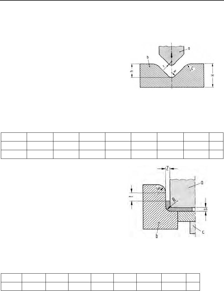
W in N m bending work
s in mm sheet thickness
b in m width of the bent part
R
m
in N/mm
2
tensile strength
with sprung pressure pad
PP
b
( ) WxF F h
W in N m bending work
x process factor;
2
3
x
F
b
in N bending force
F
PP
in N pressure pad force;
PP
b
0.25
F
F
h in m punch displacement; h = 4 · s
2
m
2.4 WswR
W in N m bending work
s in mm sheet thickness
w in m width of the bent part
R
m
in N/mm
2
tensile strength
Figure 16.10 Force-displacement diagram
16.9 Bending tooling 203
16.9 Bending tooling
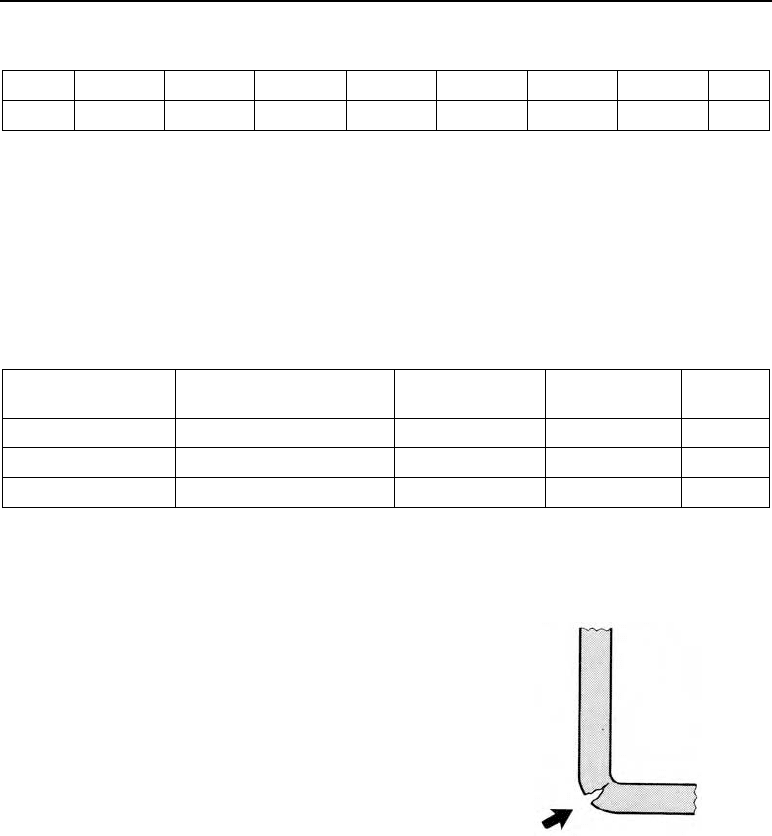
16.9.1 V-shaped die
This assembly consists of:
punch and die (Figure 16.11)
die radius r
m
r
m
= 2.5 · s
r
m
in mm die radius (mean value)
s in mm sheet thickness
curvature in die recess R
R = 0.7 (r + s)
Figure 16.11 Constructional dimensions of a
V-shaped die. a) punch, b) die
Table 16.5 Depth of the bottom die cavity h in mm
h
4 7 11 15 18 22 25 28
s
1 2 3 4 5 6 7 8
H
20 30 40 45 55 65 70 80
h in mm depth of the recess
s in mm
sheet thickness
H
in mm height of the bottom die
16.9.2 U-shaped die
This assembly consists of:
punch, die and sprung base.
Die radius r
m
r
m
= 2.5 · s
Figure 16.12 Constructional dimensions of a
U-shaped die
Table 16.6 Size of t (space between die curvatures)
t
3 4 5 6 8 10 15 20
t in mm
s
1 2 3 4 5 6 7 8
s in mm
Width of gap Z in mm
Z
max
= s
max
Z
min
= s
max
– s ·
s
max
in mm max. sheet thickness n
204 16 Bending
Table 16.7 n for side lengths of < 25 to 100 mm
n
0.15 0.10 0.10 0.08 0.08 0.07 0.07 0.06
s
1 2 3 4 5 6 7 8
s in mm sheet thickness
Curvature in die impression C
C = 0.7 (r + s)
or C = 0
Table 16.8 Tooling materials
Material no. Designation Assembly hard-
ness HRC
Punch Bottom
die
1.1550
C 110 W 1
60 u u
1.2056
90 Cr 3
64 u u
1.2842
90 Mn V 8
62 u u
16.10 Bending defects
Not all sheet metals are suited to bending, so the right choice
of stock is extremely important. Suitability for producing a
particular bent part can be determined by experimental
bending and folding. As far as the tooling allows, the grain
flow should be transverse to the bending edge. The bending
edge and the grain direction should only be in the same
direction in exceptional cases. The most common bending
defect is material cracking at the outside edge (Figure
16.13).
Figure 16.13 Bent part
cracked on the out-
side edge
16.11 Example
The aim is to manufacture angled parts as in Figure 16.3 whose width w = 35 mm, sheet thick-
ness s = 2 mm, lengths of the legs l
1
= 20 mm und l
2
= 30 mm with an inner bend radius r
i
=
10 mm and a bend angle of
D
= 90°, from the material St 1303 (soft annealed). The bend axis
is transverse to the rolling direction.
R
m
= 400 N/mm
2
, R
e
= 280 N/mm
2
, A
10
= 25 %, E = 210 000 N/mm
2

16.12 Bending machines 205
Find:
1. Length of blank
2. Smallest permissible bend radius r
i min
3. Die width dw
4. Bending force
5. Bending work
Solution:
1.
1i 2
ʌ
180° 2
es
Ll r l
D
§·
¨¸
©¹
ʌ 90° 1 2 mm
20 mm 10 mm 30 mm 67.27 mm
180° 2
§·
¨¸
©¹
2. r
i min
= c · s = 0.01 · 2 mm = 0.02 mm c from Table 16.2
r
i actual
! r
i min
3. dw = 5 · r
i
= 5 · 10 mm = 50 mm
4.
222
m
b
1.2 1.2 35 mm (2 mm) 400 N/mm
1344 N
50 mm
ws R
F
dw
5. W = x · F
b
· h =
1
3
· 1344 N · 0.025 m = 11.1 N m
50 mm
25 mm
22
dw
h
16.12 Bending machines
Bending machines are sorted according to their fields of application into machines:
1. To produce folded profiles
1.1 Press brakes
1.2 Folders (bending brakes)
2. To produce rings and tubes
2.1 Three-roll bending machines
2.2 Profile steel bending machines
3. To produce sheet profiles
3.1 Beading machines
206 16 Bending
Table 16.9 Overview of bending machines
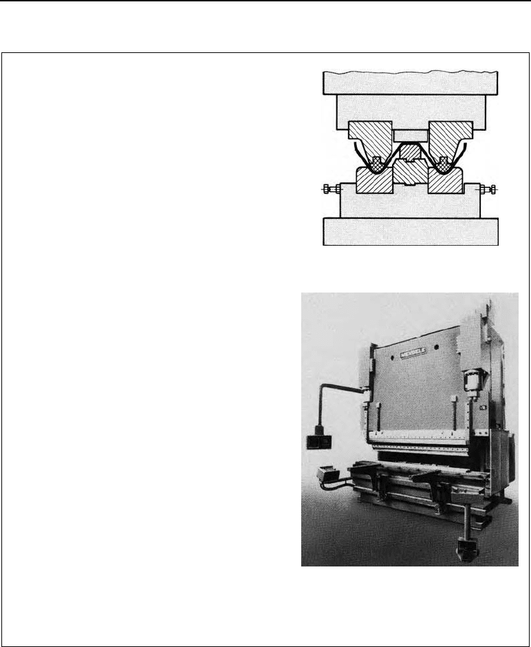
1.1 Press brakes
In press brakes, bent profiles are manufactured by
forced bending in bending dies.
The shape of the die is that of the contour to be pro-
duced.
To keep spring-back on the workpiece as low as
possible, the final impression (bottoming the punch)
during bending must be deep. Press brakes are gen-
erally built in a fracture-proof steel plate construc-
tion. The CNC-controlled press brake shown here
(F
max
= 5000 kN, max. workpiece length 4m) is
driven hydraulically. The two press cylinders are
electronically synchronised with non-contact meas-
uring equipment. The press ram is guided in four-
point guides, with no play. The machine is equipped
with a CNC-controlled automatic tool change sys-
tem. Five upper tools held on standby in a chain
system on the crosshead can be activated with a
specially-designed program and automatically posi-
tioned. The tools are clamped hydraulically in their
working position. With four lower tools, which are
moved laterally and can also be programmed, they
form mating tool sets which can produce compli-
cated profiles with no need for storage between
operations.
With the freely programmable CNC system used
here, orders are entered directly at the machine by
the operator in a dialogue system. The data entered
by this means are saved in the control system and
can be retrieved at any time. The dimensions of 50
tools can be saved in a tool library and displayed in
the form of a diagram on the screen.
Press bending die
CNC-controlled press brake with automatic
tool change system (Photograph from
Günzburger Werkzeugmaschinenfabrik works)
16.12 Bending machines 207
Table 16.9 (continued)
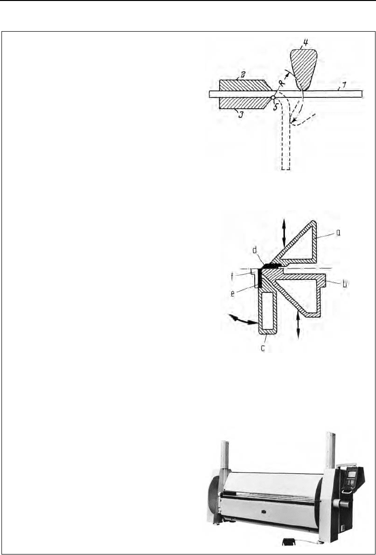
1.2 Folders (bending brakes)
Bending on a bending brake uses a folder beam
which grips the projecting workpiece and is turned
with it around the die edge.
The main elements of the bending brake are: upper
beam, lower beam and bending beam. The upper
and lower beams are the tool holders.
A track with a curved edge is fixed in the upper
beam; the sheet is bent around the track.
During the bending process the sheet being bent is
first clamped between the upper and lower beams,
then the bending beam, which can be swivelled a-
round, bends the sheet to the desired angle.
The bending brake shown here has a working width
of 2í4 m and can be used for maximum sheet thick-
nesses of 3–5 mm. It is built as a welded steel con-
struction. The upper beam is opened and closed by
means of a hydraulic cylinder. The gripping pres-
sure and the closing speed are adjustable. The lower
beam is adjusted centrally and comes with a re-
placeable bar.
The bending wing, run on a servo-hydraulic system,
ensures the bend angle is exact and there is highly
accurate repeatability. The bending wing’s special
measuring system also means that extremely small
angles can be produced.
The machine can be delivered with various control
systems, single-action program control or an MCNC
program control. With the RAS Multibend 8000
MCNC control system, data are entered in a dia-
logue with the operator, using the screen. The values
for the bend angle, the strike position and how far
the upper wing opens can all be entered, as well as a
large number of auxiliary functions.
The internal storage capacity can hold 99 program
sequences.
RAS 74.20í74.40 bending brake with servo-
hydraulic drive. (Photograph from Reinhardt Ma-
schinenbau works, 7032 Sindelfingen, Germany)
Bending with folder beam (on a bending brake)
Cross-section of the beams of a bending
brake, a) upper beam, b) lower beam, c)
bending beam, d) three-sided track, e)
flat track, f) reinforcing track
208 16 Bending
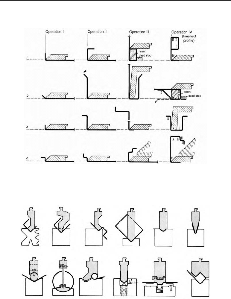
Figures 16.14 and 16.15 show working examples of the production of profiles.
Figure 16.14 Working examples of the production of profiles with bending brakes
Figure 16.15 Working examples of the production of profiles with press brakes
16.12 Bending machines 209
Table 16.9 (continued)
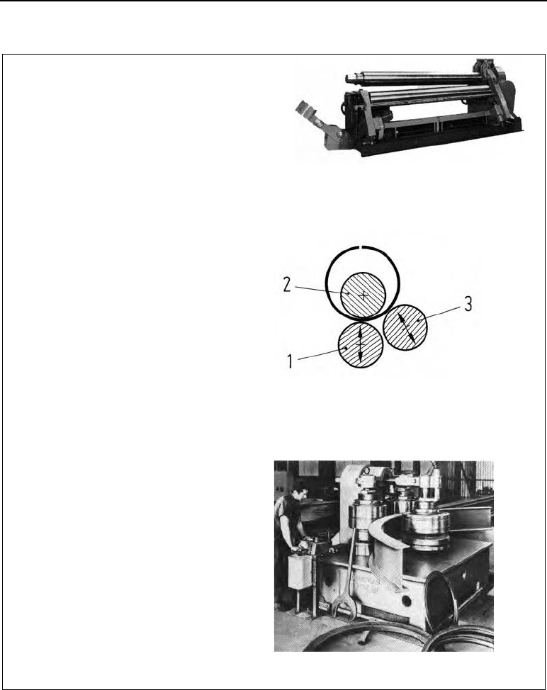
2.1 Three-roll bending machines
With three-roll bending machines the lower
rolls (1 and 3) are driven mechanically.
The top roll is idle, with no drive. To allow the
finished length of pipe to be removed, one sup-
port for this roll can be swung open.
Type UH7 three-roll sheet bending machine with
opened support (Herkules-Werke works)
Asymmetric roll layout 1 lower roll, 2 top roll, 3
bending roll
2.2 Profile steel bending machines
With these machines, the roll axes are arranged
vertically.
The rolls consist of separate components. This
means they can be adapted to the shape of the
profile to be produced, using spacer rings.
The axes of the two motor-driven side rolls are
supported in two places, once down in the ma-
chine body and once up in the crosshead.
The non-powered middle roll can be adjusted
radially.
Profile bending machine (Herkules-Werke works)
210 16 Bending
Table 16.9 (continued)
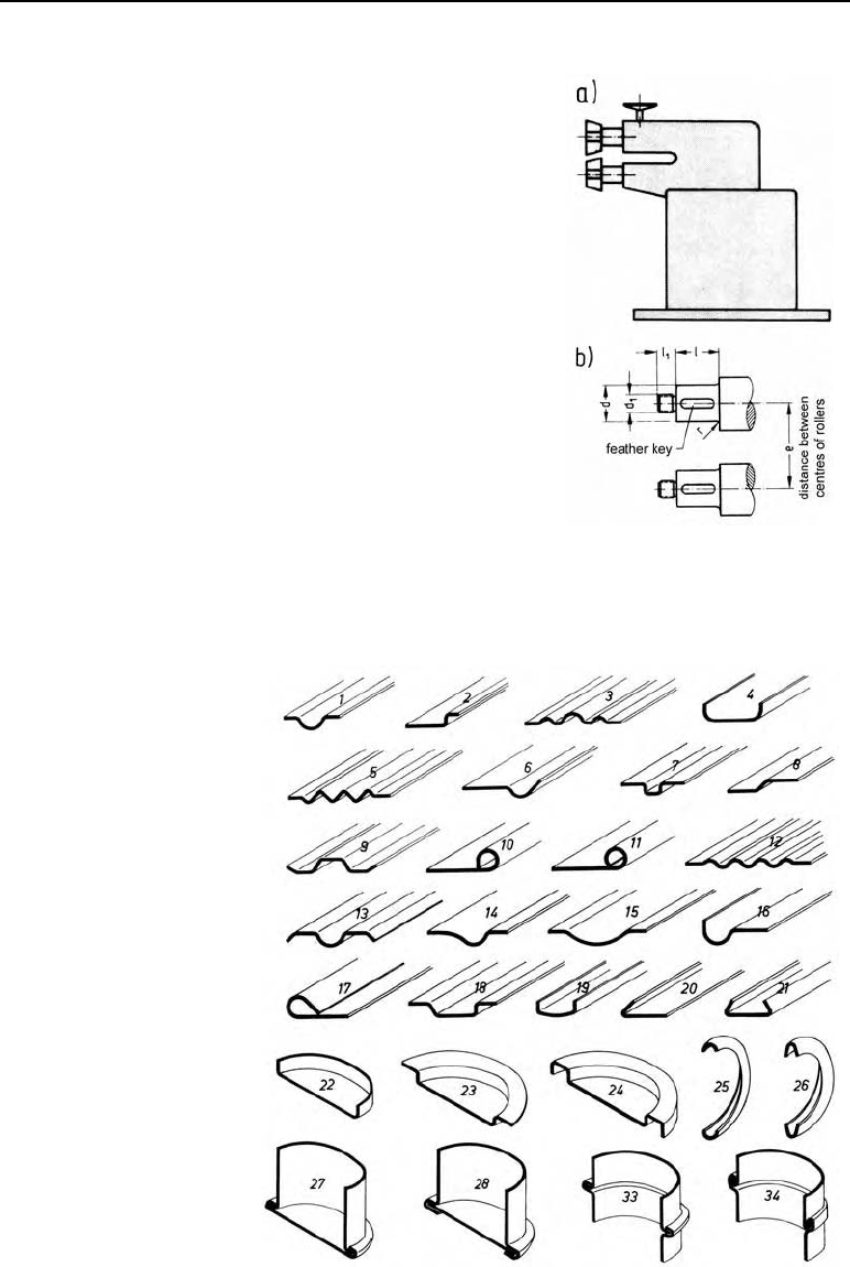
3. Beading machines
The main elements of a beading machine are two
shafts connected by a drive (gear).
The ends of the shafts hold the dies; beading,
seaming or flanging rolls.
The top roll can be adjusted vertically to set the
spacing, e.
The lower roll can be adjusted axially; this means
it can be aligned with the top roll according to the
profile to be rolled.
The rolling dies are put on the ends of the shafts.
Figure 16.6 shows typical profiles produced on
beading machines.
a) The principle of a beading machine
b) Rough dimensions of the shaft journals to
hold the dies
Figure 16.16 Profiles
produced on beading
machines (Illustration:
Stückmann & Hillen
works)