Tsch?tsch H., Koth A. Metal Forming Practise: Processes - Machines - Tools
Подождите немного. Документ загружается.

14.10 Drawing tooling (Figure 14.17) 161
The principle of the tooling layout for the
first draw is shown in Figure 14.19; Figure
14.23 shows an assembly for the second
draw.
Figure 14.23 Drawing tooling for the second
draw for a single-action press
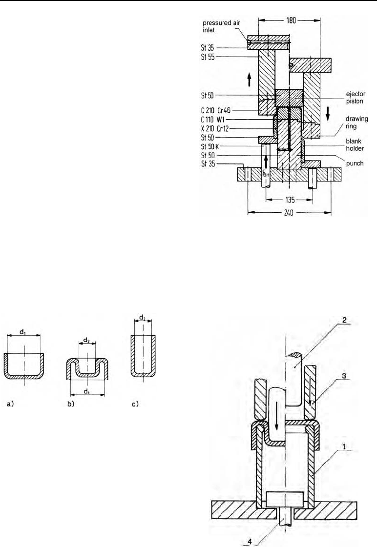
Instead of a conventional second draw, reverse (inside-out) redrawing can also be used. In
reverse redrawing, the pre-formed cup (Figure 14.2) is brought down to the next diameter
reduction by being turned inside-out. After reverse redrawing the inner walls of the drawn
cup become outer walls. Figure 14.25 shows the principle of a reverse redrawing assembly.
Fig. 14.24 (above) Reverse-redrawn workpiece, a)
before, b) during, c) after reverse redrawing.
Figure 14.25 (right). The principle of the reverse
redrawing assembly, 1 drawing ring, 2 drawing
punch, 3 blank holder, 4 ejector
162 14 Deep drawing
3. Drawing tooling for irregular flat forms e.g. for automobile manufacturing
Drawing tooling for irregular, flat forms, such as those which occur often in automobile parts,
is characterised by difficult forming conditions. Instead of a conventional drawing ring, a
shaping drawing die is used which has the negative form of the workpiece. This tooling is
produced by casting, often full mould (lost foam) casting followed by a chip-producing (cut-
ting) finishing process.
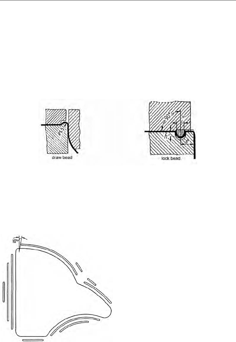
To form the shape, the tensile-compressive stresses must be accompanied by uniaxial or biax-
ial tensile and bending stresses created by a suitable tooling design. The (draw) bead shown in
Figure 14.26 is generally put on the die and the draw beads (lock beads) are arranged on the
blank holder, with gaps in the die to fit them.
Figure 14.26 Draw beads and lock beads
(range of w × h: 10 × 8 ... 20 × 25 mm)
The lock beads are of more importance than the draw beads and are positioned in places where
problems occur with varying stress ratios and an associated material flow. For example, Figure
14.27 shows the arrangement of lock beads on a drawn part.
Figure 14.27 The arrangement of lock beads on
a drawn automobile part
14.10 Drawing tooling (Figure 14.17) 163
The draw beads and lock beads mean that the material flow can be controlled, fine-tuned by
FEM simulation and ultimately the toolmaker’s experience, so that the defects of cracking,
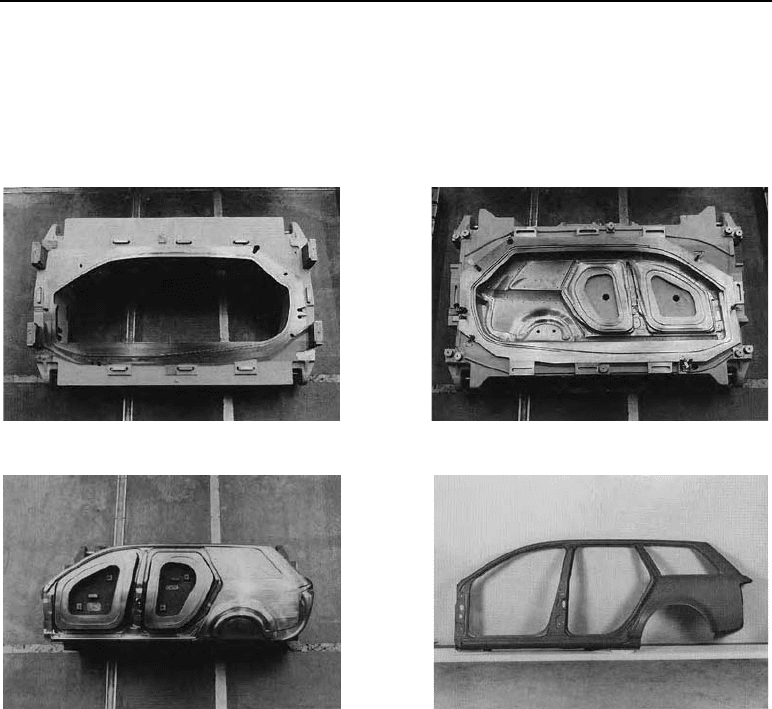
over-reduction of sheet thickness and wrinkling can be avoided. Figure 14.28 shows the deep
drawing punch, the blank holder, the drawing die and a component, the side door of an Audi
Avant automobile.
Blank holder
Drawing die
Drawing punch
Side wall component of Audi Avant
Figure 14.28 Toolset for manufacturing the Audi Avant side wall (Photograph from KUKA Werkzeug-
bau Schwarzenberg GmbH works, Germany)
The problems presented by this complicated drawing tooling mean that in practice, when pre-
developing new automobile components, prototype tooling is still required to produce a limited
number of components for test purposes, as well as FEM simulations of the viability of the
process and the construction of tooling.
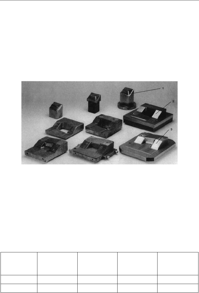
In Figure 14.29, for example, there are three toolsets for manufacturing prototype components
which allow rapid production of the tooling, and therefore also the workpieces, from 3D CAD
construction data. In version 1, the tooling is produced by casting using an alloy with a very
low melting point, MCP 137 (HEK GmbH works). This tooling can be used for up to approx.
30 parts, then it must be re-cast with the nearly 100% reusable MCP alloy. For larger numbers
of prototype parts, a Zn alloy (ZAMAK) is used internationally which requires full mould
casting followed by a chip-producing finishing process.
164 14 Deep drawing
In version 2, the tooling is made up of layers of laser-cut sheet bonded together with pins,
bolts, sometimes adhesives or, with large-scale tooling, by welding. The disadvantage of this
version are the marks on the sheet parts caused by the ridged structure of the laminated tooling,
meaning that this version is only used for automobile components which are out of sight.
However, Japanese experience shows that a great deal of time and money can be saved with
large-scale tooling.
Version 3 shows how high-speed cutting (HSC) can be used in tool manufacturing. The sur-
face quality of the tools reaches that achieved by grinding; for the relatively small component
studied here (approx. 130 mm × 100 mm × 35 mm, sheet thickness 1.5 mm; St 14) with a free-
formed surface Version 3 worked out as the best solution regarding both time and expenses.
Version 1 Version 2 Version 3
Figure 14.29 Drawing tooling for prototypes (Photograph by Sebb, Dresden University of Applied
Sciences)
(1 í punch; 2 í blank holder; 3 í drawing die)
When using the newly-developed HSC hexapod Mikromat 6X milling machine, which works
on the principle of parallel kinematics, first studies have shown that up to 40% more time can
be saved. All three versions are considerably faster and better value than normal production, as
can be seen from Table 14.6 a.
Table 14.6 a Comparison of production time and costs for prototype tooling (including CAD construc-
tion)
Version 1 í casting
Version 2 í lami-
nated object mod-
elling
Version 3 – HSC
milling
Conventional pro-
duction (milling,
electrical discharge
machining)
Time / h /
51 53.5 33.2 104.5
Order by cost
2 3 1 4

14.10 Drawing tooling (Figure 14.17) 165
Table 14.6 Drawing ring dimensions in mm
Blank D
d
1
d
2
d
3
h
1
h
2
18.5 10 13 50 20 10
22 12.5 16 50 20 10
29 16 20 50 25 13
36 20 24 63 25 13
45.5 25 29 63 25 13
58 31.5 38 80 32 16
73 40 46 80 32 16
90 50 56 100 32 16
116 63 70 125 32 20
145 80 88 160 40 20
180 100 108 200 40 20
225 125 132 250 40 25
290 160 168 315 40 25
360 200 208 400 50 25
455 250 258 500 50 32
580 315 328 630 63 32
725 400 408 800 63 32
Table 14.7 Tooling materials
Material no. Designation HRC assembly
hardness
Drawing punch Drawing die
1.1540
C 100 W1
63 × ×
1.2056
90 Cr 3
63 × ×
1.2842
90 Mn V 8
62 × ×
1.2363
105 Cr Mo V 5 – 1
63 × ×
1.2436
210 Cr W 12
62 × ×
ISO designation HV30 assembly
hardness
Drawing punch Drawing die
G 20
1400 × ×
Carbide
G 30
1200 × ×
166 14 Deep drawing
14.11 Achievable precision
Table 14.8 Height tolerances (±) in mm for cylindrical drawn parts without a flange
Height of the drawn part in mm
Material
thickness in
mm
20
21 to 30 31 to 50 51 to 100 101 to 150 151 to 200
1 0.5 0.6 0.8 1.1 1.4 1.6
1 to 2
0.6 0.8 1.0 1.3 1.7 1.8
2 to 4
0.8 1.0 1.2 1.6 1.9 2.2
Table 14.9 Height tolerances (±) in mm for cylindrical drawn parts with a flange
Height of the drawn part in mm
Material
thickness in
mm
20
21 to 30 31 to 50 51 to 100 101 to 150 151 to 200
1 0.3 0.4 0.5 0.7 0.9 1.0
1 to 2
0.4 0.5 0.6 0.8 1.1 1.2
2 to 4
0.5 0.6 0.7 0.9 1.3 1.4
Table 14.10 Diameter tolerances in mm for cylindrical hollow parts without a flange, for sheet thick-
nesses of s = 0.5 to 2.0 mm
Diameter of the drawn part in mm
Draw ratio
E
30
31 to 60 61 to 100 101 to 150 151 to 200
1.25 0.10 0.15 0.25 0.40 0.60
1.50 0.12 0.20 0.40 0.50 0.75
2.0 0.15 0.25 0.45 0.60 0.90
14.12 Defects during deep drawing 167
14.12 Defects during deep drawing
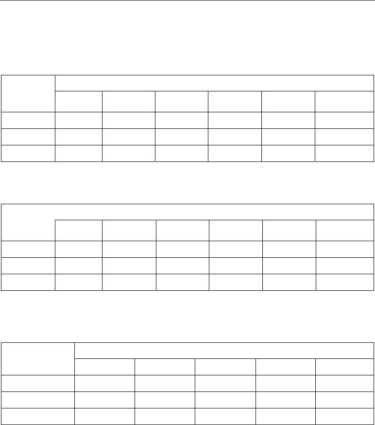
Table 14.11 Defects during deep drawing (according to G.W. Oehler)
Appearance Type of defect Cause of defect Corrective action
Material flaw
Irregular cracking
from the edge of the
wall down Cracks of
this type often only
develop days or
weeks after drawing
Too high stresses Anneal the stock directly
after drawing
Deep crack on one
side of the wall, crack
is a curved shape.
Clean edge to crack.
Transverse crack on
one side
Flaw in the sheet
caused by thicker nod-
ules or foreign bodies
pressed in, e.g. metal
chips.
Short transverse
cracks in the wall.
Black spots with
flattened areas di-
rectly above and
below them
Fine holes in the mate-
rial, porous sheet
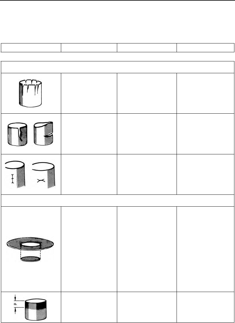
Defects in the tooling
Bottom is torn off on
all sides with no wall
forming.
The drawing tooling is
acting as a cutter, as
1. die edge curvature
too low and sharp-
edged or
2. drawing clearance
too narrow or
3. too high blank
holder pressure or
4. too high drawing
speed.
Raise the die edge ra-
dius, generally by grind-
ing the punch or drawing
ring. Reduce the blank
holder pressure. Reduce
the number of press
strokes per minute.
Bright compression
mark at height p on
the upper part of the
wall, externally.
Drawing clearance
too narrow.
Grind drawing ring or
punch.
168 14 Deep drawing
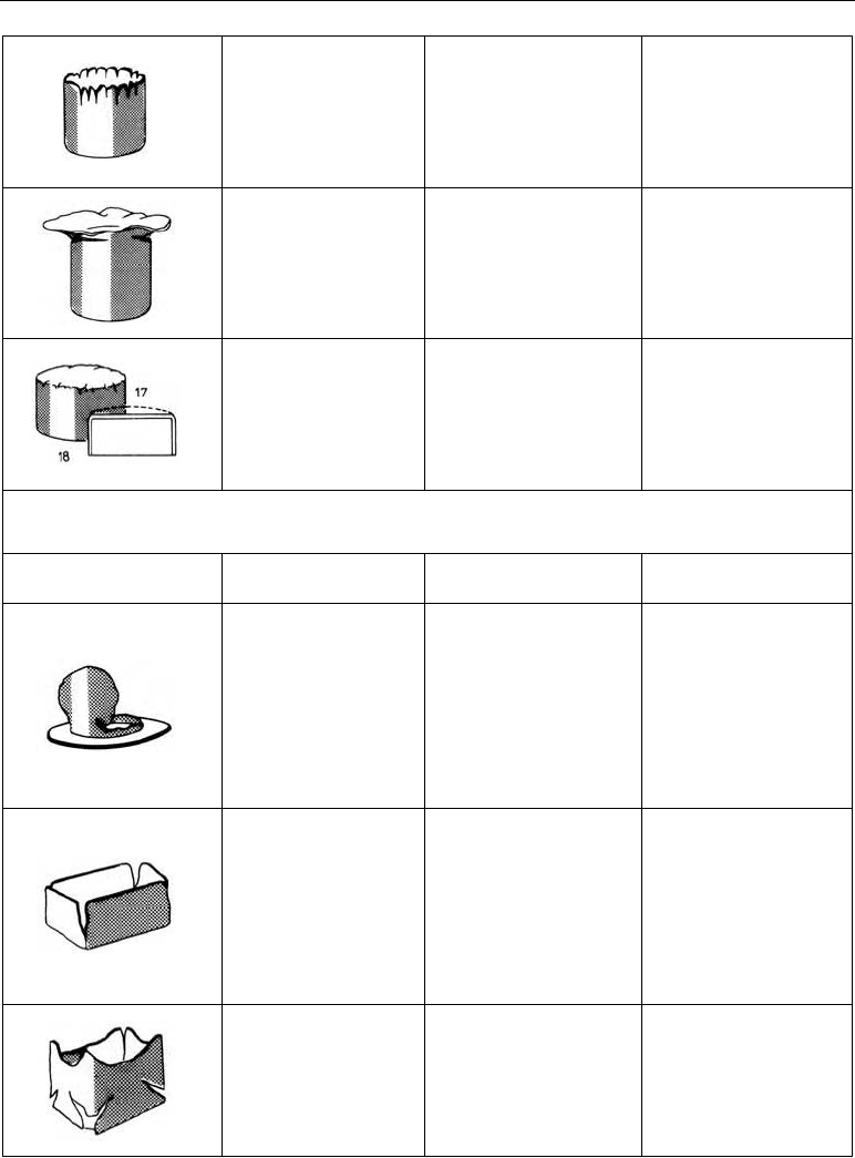
Drawing successful
except for frayed wall
edge and flattened
wrinkles.
1. Mostly drawing
clearance too wide
or
2. die edge curvature
too large.
Replace tooling to re-
duce clearance.
Draw almost success-
ful except very wrin-
kled extra flange with
horizontal cracks
beneath it.
Too high die edge cur-
vature, too low blank
holder pressure.
Grind down the surface
of the drawing ring and
reduce edge radius. Set
blank holder pressure
higher.
Blistering at the bot-
tom edges. Bottom
bulges as shown by
the dashed line
1. Bad punch ventila-
tion,
2. occasionally also
heavily-worn die ra-
dius
Install or widen vents.
Polish the die radius.
Wrong blank size or wrong step difference
Appearance Type of defect Cause of defect Corrective action
Only a short wall stub
is formed, at about
the height of the die
edge curvature, then
the bottom tears off.
Too great a difference
between steps consider-
ing the drawing quality
of the sheet.
Punch off-centre to the
drawing ring.
Determine
E
value (=
highest permissible D/d
ratio) using the cup test
procedure.
Perhaps make steps
smaller or select sheet of
higher drawing quality.
Adjust tooling correctly.
Tearing in the corners
of rectangles, starting
out at the edge and
moving down to-
wards the bottom
corner.
1. Lack of material in
the corners due to
incorrect blank siz-
ing.
2. Drawing clearance
too narrow in the
corners.
Change blank. Rectan-
gular draws requires a
greater drawing clear-
ance in the corners than
at the sides.
Cracks starting in the
bottom corners of
rectangular draws,
then moving out di-
agonally.
1. Excess material in
the corners.
2. Differences between
steps too great in the
corners.
Change the blank. Make
steps smaller or use
higher-quality deep
drawing sheet.
14.13 Example 169
Earing on one side of
the wall edge or on
the sheet flange.
1. Blank inserted off-
centre.
2. Irregular blank hol-
der pressure.
3. Off-centre position-
ing of the punch in
the drawing ring
(rarely).
4. Irregular sheet
thickness
Use guide pins.
Align tooling.
Operating errors
Sheet flange too wide
on one side near the
web.
Blank inserted off-
centre.
Fit stop pins.
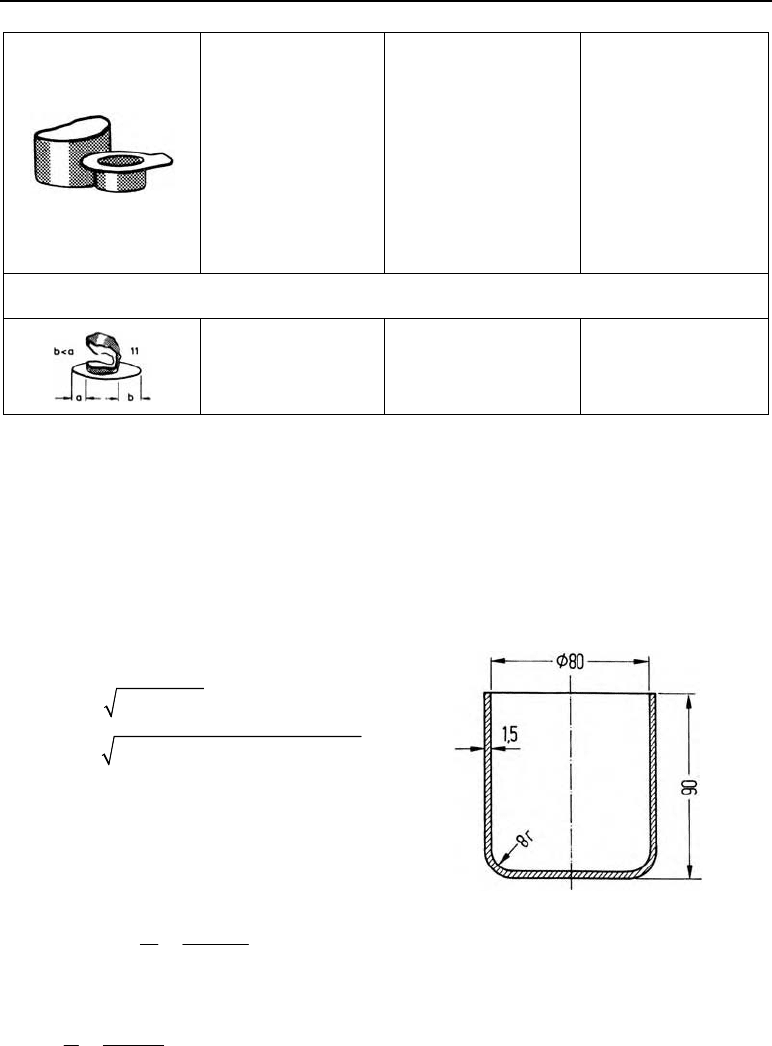
14.13 Example
The aim is to manufacture sheet shells as in Figure 14.30 on a double-action drawing press.
Where: material St 1303
Find: blank diameter D, force, mechanical work (for the first draw)
Solution:
1. Determining blank size
2
4Dd dh
2
(80mm) 4 80mm 90mm
187.6 mmD
188 m selectedD
2. Determining the number of draws required
2.1. The actual draw ratio
actual
188 mm
2.35
80 mm
D
d
E
2.2. Diameter-wall thickness ratio d/s
80 mm
53.3
1.5 mm
d
s
2.3. Permissible draw ratio for the first draw
E
perm
| 2.05 from Table 14.2, page 151
170 14 Deep drawing
2.4. Decision
as
0 perm actual
EE
2.05 2.35
the part can not be produced in one draw as in Figure 14.26.
2.5. Deep drawing steps
1. draw
1
0
188 mm
91.7 mm
2.05
D
d
E
1
2
1
91.7 mm
70.5 mm
1.3
d
d
E
i.e. the drawn part can be produced with two draws.
So that it is not necessary to go up to the deformability limit at the first draw,
d
1
= 94.0 mm is selected.
Thus
actual
188 mm
2.0
94 mm
E
At the second draw, this then produces an
E
actual
of
1
actual
2
94 mm
1.17
80 mm
d
d
E
i.e. d
2
will also be safely achieved.
2.6. Height of the cup after the first draw
From
2
4Dd dh we get:
22 2 2 2 2
1
(188 mm) (94 mm) 35 344 mm 8836 mm
4 4 94 mm 376 mm
Dd
h
d
h
1
= 70.5 mm.