Tarek Ahmed. Reservoir engineering handbook
Подождите немного. Документ загружается.


The effect of capillary pressure is usually neglected because the capillary
pressure gradient is generally small and, thus, Equations 14-19 and 14-21
are reduced to:
and
where i
g
= gas injection rate, bbl/day
g
= gas viscosity, cp
g
= gas density, g/cm
3
From the definition of water cut, i.e., f
w
= q
w
/(q
w
+ q
o
), we can see that
the limits of the water cut are 0 and 100%. At the irreducible (connate)
water saturation, the water flow rate q
w
is zero and, therefore, the water
cut is 0%. At the residual oil saturation point, S
or
, the oil flow rate is zero
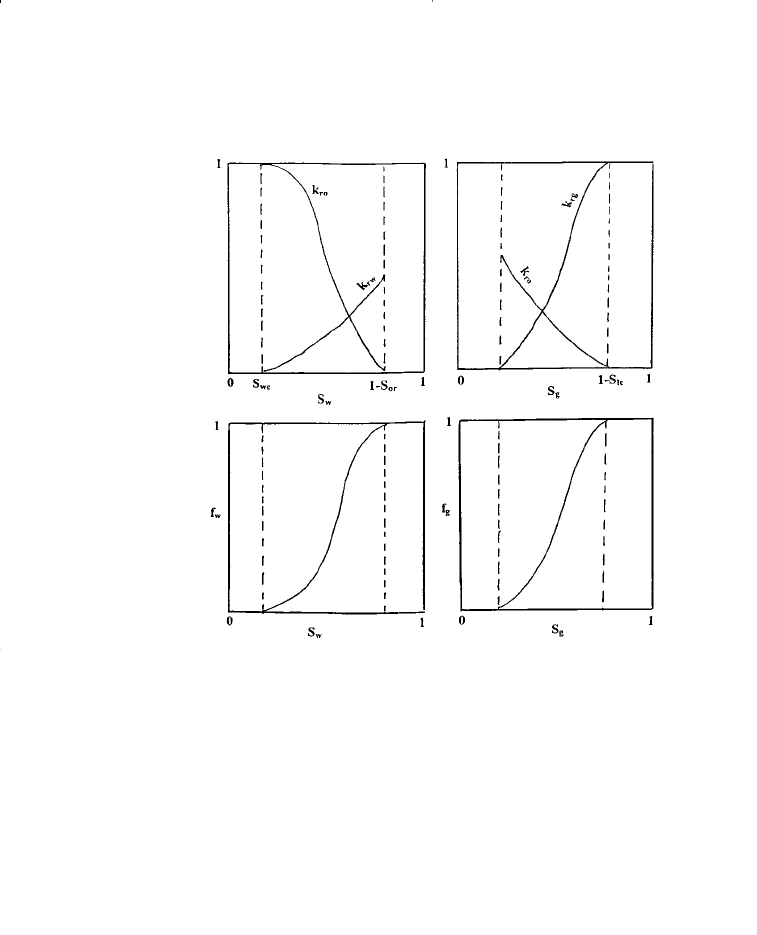
and the water cut reaches its upper limit of 100%. The shape of the water
cut versus water saturation curve is characteristically S-shaped, as shown
in Figure 14-12. The limits of the f
w
curve (0 and 1) are defined by the
end points of the relative permeability curves.
The implications of the above discussion are also applied to defining
the relationship that exists between fg and gas saturation, as shown in
Figure 14-12.
f
kk A
i
k
k
g
ro
og
go
ro
rg
g
o
=
−
−
(
)
(
)
[]
+
1
0 001127
0 433
1
.()
. sin
µ
ρρ
α
µ
µ
f
kk A
i
k
k
w
ro
ow
wo
ro
rw
w
o
=
−
−
(
)
(
)
[]
+
1
0 001127
0 433
1
.()
. sin
µ
ρρ
α
µ
µ
(14 - 22)
f
kk A
i
p
x
k
k
g
rg
og
c
go
ro
rg
g
o
=
−
∂
∂
−
−
(
)
(
)
+
1
0 001127
0 433
1
.()
. sin
µ
ρρ
α
µ
µ
(14 - 21)
888 Reservoir Engineering Handbook
Reservoir Eng Hndbk Ch 14 2001-10-25 17:37 Page 888
Note that, in general, any influences that cause the fractional flow
curve to shift upward (i.e., increase in f
w
or f
g
) will result in a less
efficient displacement process. It is essential, therefore, to determine the
effect of various component parts of the fractional flow equation on
the displacement efficiency. Note that for any two immiscible fluids,
e.g., water and oil, the fraction of the oil (oil cut) f
o
flowing at any point
in the reservoir is given by:
The above expression indicates that during the displacement of oil by
waterflood, an increase in f
w
at any point in the reservoir will cause a
proportional decrease in f
o
and oil mobility. Therefore, the objective is
to select the proper injection scheme that could possibly reduce the water
fractional flow. This can be achieved by investigating the effect of the
injected water viscosity, formation dip angle, and water-injection rate on
the water cut. The overall effect of these parameters on the water frac-
tional flow curve are discussed next.
ff f f
ow o w
+= =−11 or
Principles of Waterflooding 889
Figure 14-12. Fractional flow curves a function of saturations.
Reservoir Eng Hndbk Ch 14 2001-10-25 17:37 Page 889
Effect of Water and Oil Viscosities
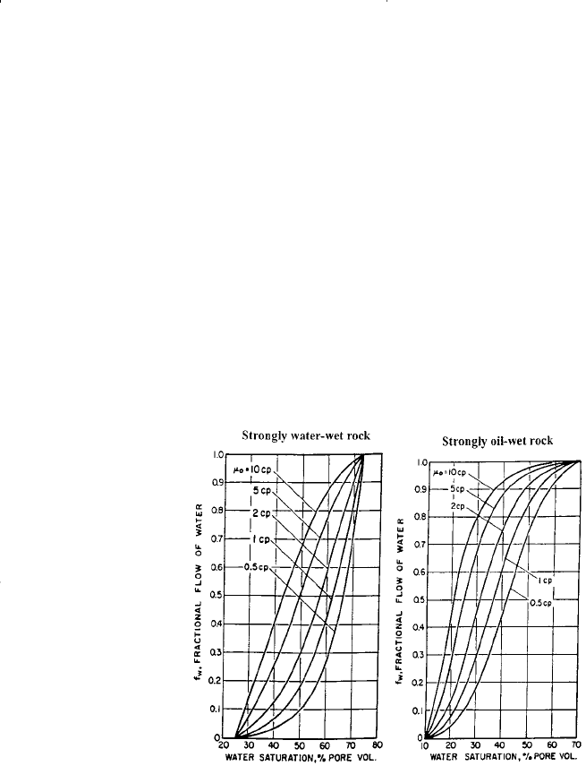
Figure 14-13 shows the general effect of oil viscosity on the fraction-
al flow curve for both water-wet and oil-wet rock systems. This illus-
tration reveals that regardless of the system wettability, a higher oil vis-
cosity results in an upward shift (an increase) in the fractional flow
curve. The apparent effect of the water viscosity on the water fraction-
al flow is clearly indicated by examining Equation 14-22. Higher
injected water viscosities will result in an increase in the value of the
denominator of Equation 14-22 with an overall reduction in f
w
(i.e., a
downward shift).
Figure 14-13. Effect of oil viscosity on f
w
.
Effect of Dip Angle and Injection Rate
To study the effect of the formation dip angle and the injection rate
on the displacement efficiency, consider the water fractional flow equa-
tion as represented by Equation 14-22. Assuming a constant injection
rate and realizing that (
w
–
o
) is always positive and in order to isolate
890 Reservoir Engineering Handbook
Reservoir Eng Hndbk Ch 14 2001-10-25 17:37 Page 890

the effect of the dip angle and injection rate on f
w
, Equation 14-22 is
expressed in the following simplified form:
where the variables X and Y are a collection of different terms that are
all considered positives and given by:
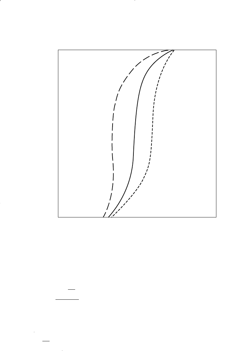
• Updip flow, i.e., sin() is positive. Figure 14-14 shows that when the
water displaces oil updip (i.e., injection well is located downdip), a
more efficient performance is obtained. This improvement is due to the
fact that the term X sin()/i
w
will always remain positive, which leads
to a decrease (downward shift) in the f
w
curve. Equation 14-23 also
reveals that a lower water-injection rate i
w
is desirable since the nomi-
nator 1 – [X sin()/i
w
] of Equation 14-23 will decrease with a lower
injection rate i
w
, resulting in an overall downward shift in the f
w
curve.
• Downdip flow, i.e., sin() is negative. When the oil is displaced
downdip (i.e., injection well is located updip), the term X sin()/i
w
will always remain negative and, therefore, the numerator of Equation
14-23 will be 1+[X sin()/i
w
], i.e.:
which causes an increase (upward shift) in the f
w
curve. It is beneficial,
therefore, when injection wells are located at the top of the structure to
inject the water at a higher injection rate to improve the displacement
efficiency.
f
X
i
Y
w
w
=
+
(
)
+
1
1
sin α
X
kk A
Y
k
k
ro w o
o
ro
rw
w
o
=
()()()
−
()
=
0 001127 0 433.. ρρ
µ
µ
µ
f
X
i
Y
w
w
=
−
(
)
+
1
1
sin α
(14 - 23)
Principles of Waterflooding 891
Reservoir Eng Hndbk Ch 14 2001-10-25 17:37 Page 891
It is interesting to reexamine Equation 14-23 when displacing the oil
downdip. Combining the product X sin() as C, Equation 14-23 can be
written:
The above expression shows that the possibility exists that the water cut
f
w
could reach a value greater than unity (f
w
> 1) if:
This could only occur when displacing the oil downdip at a low water-
injection rate i
w
. The resulting effect of this possibility is called a
C
i
Y
w
>
f
C
i
Y
w
w
=
+
+
1
1
892 Reservoir Engineering Handbook
Figure 14-14. Effect of dip angle on f
w
.
Down-dip
No-dip
Up-dip
1
1
0
0
S
w
f
w
Reservoir Eng Hndbk Ch 14 2001-10-25 17:37 Page 892

counterflow, where the oil phase is moving in a direction opposite to
that of the water (i.e., oil is moving upward and the water downward).
When the water injection wells are located at the top of a tilted forma-
tion, the injection rate must be high to avoid oil migration to the top of
the formation.
Note that for a horizontal reservoir, i.e., sin() = 0, the injection rate
has no effect on the fractional flow curve. When the dip angle is zero,
Equation 14-22 is reduced to the following simplified form:
In waterflooding calculations, the reservoir water cut f
w
and the
water–oil ratio WOR are both traditionally expressed in two different
units: bb/bbl and STB/STB. The interrelationships that exist between
these two parameters are conveniently presented below, where
Q
o
= oil flow rate, STB/day
q
o
= oil flow rate, bbl/day
Q
w
= water flow rate, STB/day
q
w
= water flow rate, bbl/day
WOR
s
= surface water–oil ratio, STB/STB
WOR
r
= reservoir water–oil ratio, bbl/bbl
f
ws
= surface water cut, STB/STB
f
w
= reservoir water cut, bbl/bbl
i) Reservoir f
w
– Reservoir WOR
r
Relationship
Reservoir f
w
– Reservoir WOR
r
Relationship
Substituting for WOR gives:
f
WOR
WOR
w
r
r
=
+
()
1
14 - 25
f
q
qq
q
q
q
q
w
w
wo
w
o
w
o
=
+
=
+1
f
k
k
w
ro
rw
w
o
=
+
1
1
µ
µ
(14 - 24)
Principles of Waterflooding 893
Reservoir Eng Hndbk Ch 14 2001-10-25 17:37 Page 893

Solving for WOR
r
gives:
ii) Reservoir f
w
– Surface WOR
s
Relationship
By definition:
Introducing the surface WOR
s
into the above expression gives:
Solving for WOR
s
yields:
iii) Reservoir WOR
r
– Surface WOR
s
Relationship
From the definition of WOR:
Introducing the surface WOR
s
into the above expression gives:
WOR WOR
B
B
r
s
w
o
=
()
()
14 - 29
WOR
q
q
QB
QB
Q
Q
B
B
r
w
o
ww
oo
w
o
w
o
== =
WOR
B
B
f
Bf
Bf
s
o
w
w
ow
ww
=
−
=
−
()
()
1
1
1
14 - 28
f
B WOR
B WOR B
w
ws
wso
=
+
()
14 - 27
f
q
qq
QB
QB QB
Q
Q
B
Q
Q
BB
w
w
wo
ww
ww oo
w
o
w
w
o
wo
=
+
=
+
=
+
WOR
f
f
f
r
w
w
w
=
−
=
−
()
1
1
1
1
14 - 26
894 Reservoir Engineering Handbook
Reservoir Eng Hndbk Ch 14 2001-10-25 17:37 Page 894

or
iv) Surface f
ws
– Surface WOR
s
Relationship
or
v) Surface f
ws
– Reservoir f
w
Relationship
Example 14-5
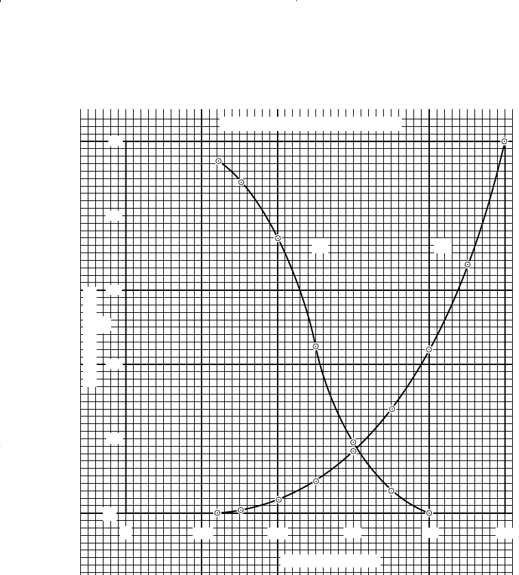
Use the relative permeability as shown in Figure 14-15 to plot the
fractional flow curve for a linear reservoir system with the following
properties:
Dip angle = 0 Absolute permeability = 50 md
B
o
= 1.20 bbl/STB B
w
= 1.05 bbl/STB
o
= 45 lb/ft
3
w
= 64.0 lb/ft
3
w
= 0.5 cp Cross-sectional area A = 25,000 ft
2
f
B
B
f
B
ws
o
w
w
o
=
−
+
()
1
1
14 - 31
f
WOR
WOR
ws
s
s
=
+
()
1
14 - 30
f
Q
QQ
Q
Q
Q
Q
ws
w
wo
w
o
w
o
=
+
=
+1
WOR WOR
B
B
s
r
o
w
=
()
Principles of Waterflooding 895
Reservoir Eng Hndbk Ch 14 2001-10-25 17:37 Page 895
Perform the calculations for the following values of oil viscosity:
0
= 0.5,
1.0, 5, and 10 cp.
Solution
For a horizontal system, Equation 14-24 can be used to calculate f
w
as
a function of saturation.
896 Reservoir Engineering Handbook
0.
0
0.2 0.4 0.6 0.8 1.0
0.2
0.4
0.6
0.8
1.0
RELATIVE PERMEABILITY CURVE
Relative Permeability
S
w
– Water Saturation
k
0
k
ro
k
rw
Figure 14-15. Relative permeability curves for Example 14-5.
Reservoir Eng Hndbk Ch 14 2001-10-25 17:37 Page 896
S
w
k
ro
k
rw
k
ro
/k
rw
o
=0.5
o
=1.0
o
=5
o
=10
0.24 0.95 0.00 00 0 0 0 0
0.30 0.89 0.01 89.0 0.011 0.022 0.101 0.183
0.40 0.74 0.04 18.5 0.051 0.098 0.351 0.519
0.50 0.45 0.09 5.0 0.17 0.286 0.667 0.800
0.60 0.19 0.17 1.12 0.47 0.641 0.899 0.947
0.65 0.12 0.28 0.43 0.70 0.823 0.459 0.979
0.70 0.06 0.22 0.27 0.79 0.881 0.974 0.987
0.75 0.03 0.36 0.08 0.93 0.962 0.992 0.996
0.78 0.00 0.41 0 1.00 1.000 1.000 1.000
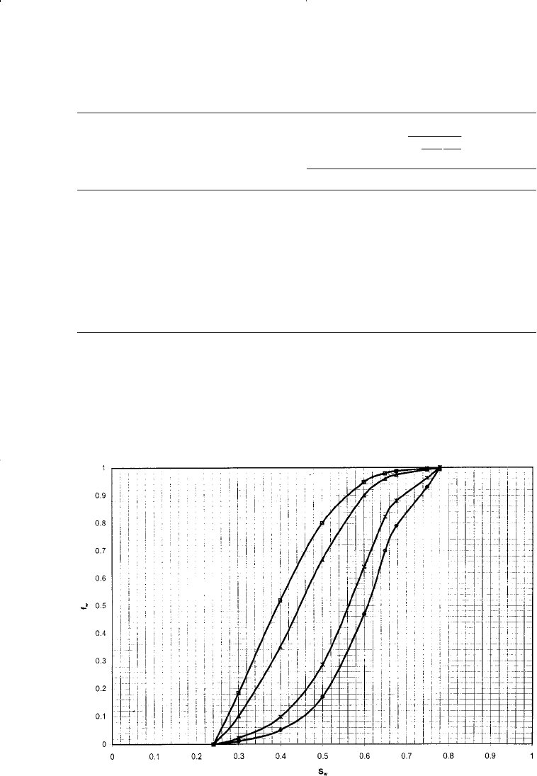
Results of the above example are documented graphically in Figure 14-16,
which shows the apparent effect of oil viscosity on the fractional flow
curve.
f
w
1
1
k
k
ro
rw
=
+
µ
µ
w
o
Principles of Waterflooding 897
Figure 14-16. Effect of
o
on f
w
.
Reservoir Eng Hndbk Ch 14 2001-10-25 17:37 Page 897
