Tarek Ahmed. Reservoir engineering handbook
Подождите немного. Документ загружается.


since the increasing slope would imply that the gas-occupied pore vol-
ume was increasing with time.
Form 2. In terms of B
g
From the definition of the gas formation volume factor, it can be
expressed as:
Combining the above expression with Equation 13-1 gives:
where V = volume of gas originally in place, ft
3
G = volume of gas originally in place, scf
p
i
= original reservoir pressure
z
i
= gas compressibility factor at p
i
Equation 13-13 can be combined with Equation 13-7, to give:
Equation 13-14 suggests that to calculate the initial gas volume, the
only information required is production data, pressure data, gas specific
gravity for obtaining z-factors, and reservoir temperature. Early in the
producing life of a reservoir, however, the denominator of the right-hand
side of the material balance equation is very small, while the numerator
is relatively large. A small change in the denominator will result in a
large discrepancy in the calculated value of initial gas in place. There-
fore, the material balance equation should not be relied on early in the
producing life of the reservoir.
Material balances on volumetric gas reservoirs are simple. Initial gas
in place may be computed from Equation 13-14 by substituting cumula-
tive gas produced and appropriate gas formation volume factors at corre-
sponding reservoir pressures during the history period. If successive cal-
culations at various times during the history give consistent values for
initial gas in place, the reservoir is operating under volumetric control
G
GB
BB
pg
ggi
=
-
(13-14)
p
T
zT
p
V
G
sc
sc
i
i
= (13 -13)
B
V
G
gi
=
838 Reservoir Engineering Handbook
Reservoir Eng Hndbk Ch 13 2001-10-24 15:13 Page 838
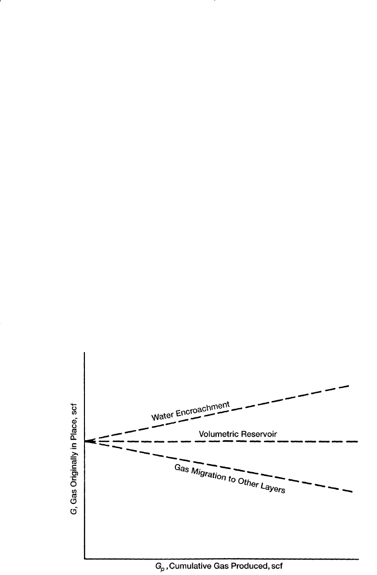
and computed G is reliable, as shown in Figure 13-6. Once G has been
determined and the absence of water influx established in this fashion,
the same equation can be used to make future predictions of cumulative
gas production function of reservoir pressure.
Ikoku (1984) points out that successive application of Equation 13-14
will normally result in increasing values of the gas initially in place G
with time if water influx is occurring. If there is gas leakage to another
zone due to bad cement jobs or casing leaks, however, the computed
value of G may decrease with time.
Example 13-3
After producing 360 MMscf of gas from a volumetric gas reservoir,
the pressure has declined from 3200 psi to 3000 psi, given:
B
gi
= 0.005278 ft
3
/scf
B
g
= 0.005390 ft
3
/scf
a. Calculate the gas initially in place.
Gas Reservoirs 839
Figure 13-6. Graphical determination of the gas initially in place G.
Reservoir Eng Hndbk Ch 13 2001-10-24 15:13 Page 839

b. Recalculate the gas initially in place assuming that the pressure mea-
surements were incorrect and the true average pressure is 2900 psi.
The gas formation volume factor at this pressure is 0.00558 ft
3
/scf.
Solution
a. Using Equation 13-14, calculate G.
b. Recalculate G by using the correct value of B
g
.
Thus, an error of 100 psia, which is only 3.5% of the total reservoir
pressure, resulted in an increase in calculated gas in place of approxi-
mately 160%, a 2
1
⁄2-fold increase. Note that a similar error in reservoir
pressure later in the producing life of the reservoir will not result in an
error as large as that calculated early in the producing life of the reservoir.
Water-Drive Gas Reservoirs
If the gas reservoir has a water drive, then there will be two unknowns
in the material balance equation, even though production data, pressure,
temperature, and gas gravity are known. These two unknowns are initial
gas in place and cumulative water influx. In order to use the material bal-
ance equation to calculate initial gas in place, some independent method
of estimating W
e
, the cumulative water influx, must be developed as dis-
cussed in Chapter 11.
Equation 13-14 can be modified to include the cumulative water influx
and water production to give:
The above equation can be arranged and expressed as:
G
W
BB
GB WB
BB
e
ggi
pg pw
ggi
+
-
=
+
-
(13-16)
G
GB W WB
BB
pg e p w
ggi
=
--
-
()
(13-15)
G MMMscf=
¥
-
=
360 10 0 00668
0 00558 0 005278
6 652
6
(. )
..
.
G MMMscf=
¥
-
=
360 10 0 00539
0 00539 0 005278
17 325
6
(. )
..
.
840 Reservoir Engineering Handbook
Reservoir Eng Hndbk Ch 13 2001-10-24 15:13 Page 840
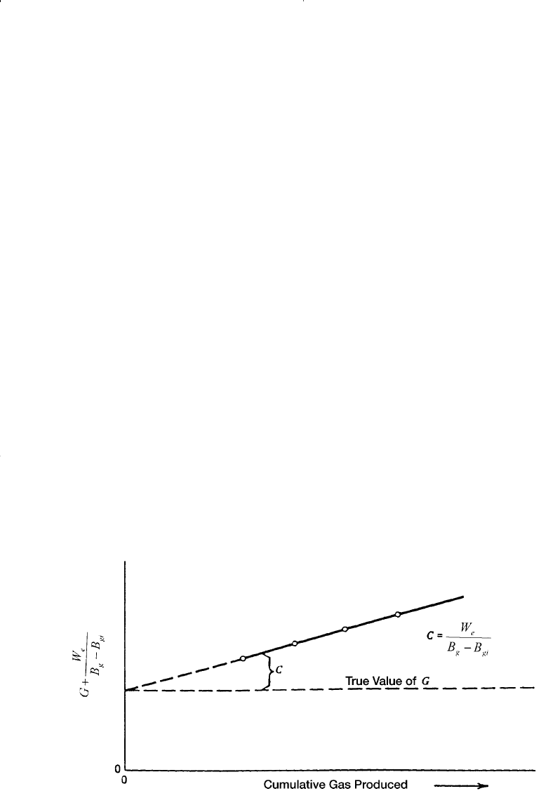
Equation 13-16 reveals that for a volumetric reservoir, i.e., W
e
= 0, the
right-hand side of the equation will be constant regardless of the amount
of gas G
p
which has been produced. For a water-drive reservoir, the val-
ues of the right-hand side of Equation 13-16 will continue to increase
because of the W
e
/(B
g
- B
gi
) term. A plot of several of these values at
successive time intervals is illustrated in Figure 13-7. Extrapolation of
the line formed by these points back to the point where G
p
= 0 shows the
true value of G, because when G
p
= 0, then W
e
/(B
g
- B
gi
) is also zero.
This graphical technique can be used to estimate the value of We,
because at any time the difference between the horizontal line (i.e., true
value of G) and the sloping line [G + (W
e
)/(B
g
- B
gi
) will give the value
of W
e
/(B
g
- B
gi
).
Because gas often is bypassed and trapped by the encroaching water,
recovery factors for gas reservoirs with water drive can be significantly
lower than for volumetric reservoirs produced by simple gas expansion.
In addition, the presence of reservoir heterogeneities, such as low-perme-
ability stringers or layering, may reduce gas recovery further. As noted
previously, ultimate recoveries of 80% to 90% are common in volumetric
gas reservoirs, while typical recovery factors in water-drive gas reser-
voirs can range from 50% to 70%.
Gas Reservoirs 841
Figure 13-7. Effect of water influx on calculating the gas initially in place.
Reservoir Eng Hndbk Ch 13 2001-10-24 15:13 Page 841

MATERIAL BALANCE EQUATION
AS A STRAIGHT LINE
Havlena and Odeh (1963) expressed the material balance in terms of
gas production, fluid expansion, and water influx as:
Underground Gas Water expansion/ Water
=+ +
withdrawal expansion pore compaction influx
or
Using the nomenclature of Havlena and Odeh, as described in Chapter
11, gives:
F = G (E
g
+ E
f,w
) + W
e
B
w
(13-18)
with the terms F, E
g
, and E
f,w
as defined by:
• Underground fluid withdrawal F:
F = G
p
B
g
+ W
p
B
w
(13-19)
• Gas expansion E
g
:
E
g
= B
g
- B
gi
(13-20)
• Water and rock expansion E
f,w
:
Assuming that the rock and water expansion term E
f,w
is negligible in
comparison with the gas expansion E
g
, Equation 13-18 is reduced to:
F = G E
g
+ W
e
B
w
(13-22)
EB
cS c
S
fw gi
wwi f
wi
,
()
=
+
-1
(13- 21)
GB WB GB B GB
cS c
S
p
WB
pg pw g gi gi
wwi f
wi
ew
+=-+
+
-
+
()
()
1
D
(13-17)
842 Reservoir Engineering Handbook
Reservoir Eng Hndbk Ch 13 2001-10-24 15:13 Page 842
Finally, dividing both sides of the equation by E
g
gives:
Using the production, pressure and PVT data, the left-hand side of this
expression should be plotted as a function of the cumulative gas produc-
tion, G
p
. This is simply for display purposes to inspect its variation dur-
ing depletion. Plotting F/E
g
versus production time or pressure decline,
Dp, can be equally illustrative.
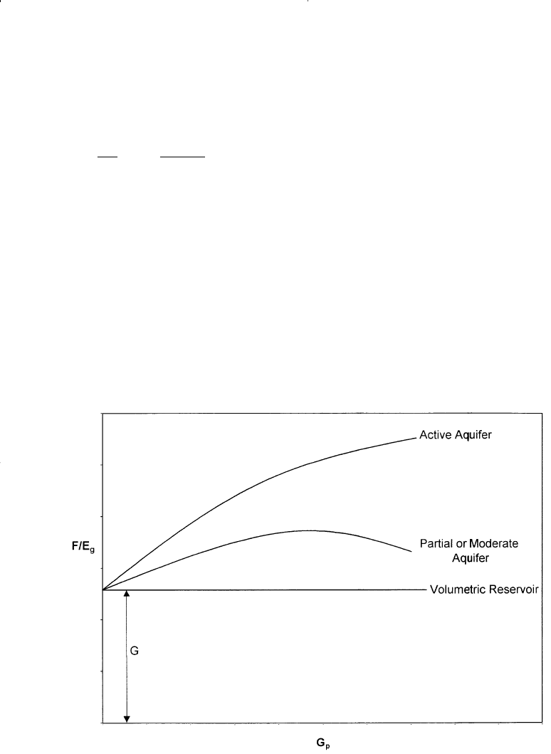
Dake (1994) presented an excellent discussion of the strengths and
weaknesses of the MBE as a straight line. He points out that the plot will
have one of the three shapes depicted in Figure 13-8. If the reservoir is of
the volumetric depletion type, W
e
= 0, then the values of F/E
g
evaluated,
F
E
G
WB
E
g
ew
g
=+ (13 - 23)
Gas Reservoirs 843
Figure 13-8. Defining the reservoir-driving mechanism.
Reservoir Eng Hndbk Ch 13 2001-10-24 15:13 Page 843
say, at six monthly intervals, should plot as a straight line parallel to the
abscissa—whose ordinate value is the GIIP.
Alternatively, if the reservoir is affected by natural water influx then
the plot of F/E
g
will usually produce a concave downward shaped arc
whose exact form is dependent upon the aquifer size and strength and the
gas off-take rate. Backward extrapolation of the F/E
g
trend to the ordi-
nate should nevertheless provide an estimate of the GIIP (W
e
~ 0); how-
ever, the plot can be highly nonlinear in this region yielding a rather
uncertain result. The main advantage in the F/E
g
versus G
p
plot is that it
is much more sensitive than other methods in establishing whether the
reservoir is being influenced by natural water influx or not.
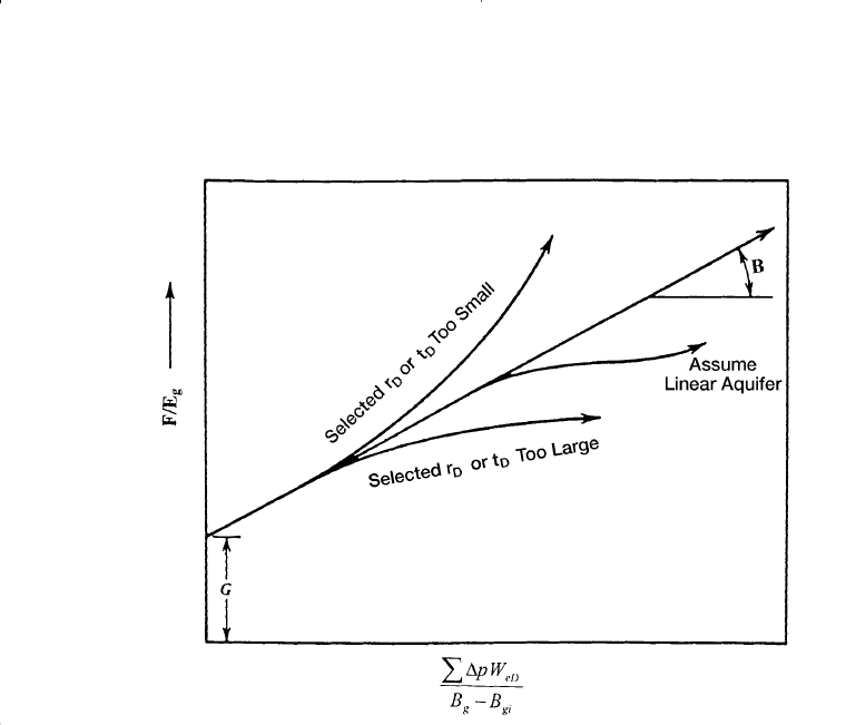
The graphical presentation of Equation 13-23 is illustrated by Figure
13-9. A graph of F/E
g
vs. SDp W
eD
/E
g
yields a straight line, provided the
unsteady-state influx summation, SDp W
eD
, is accurately assumed. The
resulting straight line intersects the y-axis at the initial gas in place G and
has a slope equal to the water influx constant B.
Nonlinear plots will result if the aquifer is improperly characterized. A
systematic upward or downward curvature suggests that the summation
844 Reservoir Engineering Handbook
Figure 13-9. Havlena-Odeh MBE plot for a gas reservoir.
Reservoir Eng Hndbk Ch 13 2001-10-24 15:13 Page 844

term is too small or too large, respectively, while an S-shaped curve indi-
cates that a linear (instead of a radial) aquifer should be assumed. The
points should plot sequentially from left to right. A reversal of this plot-
ting sequence indicates that an unaccounted aquifer boundary has been
reached and that a smaller aquifer should be assumed in computing the
water influx term.
A linear infinite system rather than a radial system might better repre-
sent some reservoirs, such as reservoirs formed as fault blocks in salt
domes. The van Everdingen-Hurst dimensionless water influx W
eD
is
replaced by the square root of time as:
where C = water influx constant ft
3
/psi
t = time (any convenient units, i.e., days, year)
The water influx constant C must be determined by using the past pro-
duction and pressure of the field in conjunction with Havlena-Odeh
methodology. For the linear system, the underground withdrawal F is
plotted versus [S Dp
n
Zt - t
n
/(B - B
gi
)] on a Cartesian coordinate graph.
The plot should result in a straight line with G being the intercept and the
water influx constant C being the slope of the straight line.
To illustrate the use of the linear aquifer model in the gas MBE as
expressed as an equation of straight line, i.e., Equation 13-23, Havlena
and Odeh proposed the following problem.
Example 13-4
The volumetric estimate of the gas initially in place for a dry-gas
reservoir ranges from 1.3 to 1.65 ¥ 10
12
scf. Production, pressures and
pertinent gas expansion term, i.e., E
g
= B
g
- B
gi
, are presented in Table
13-1. Calculate the original gas in place G.
Solution
Step 1. Assume volumetric gas reservoir.
Step 2. Plot (p/z) versus G
p
or G
p
B
g
/(B
g
- B
gi
) versus G
p
.
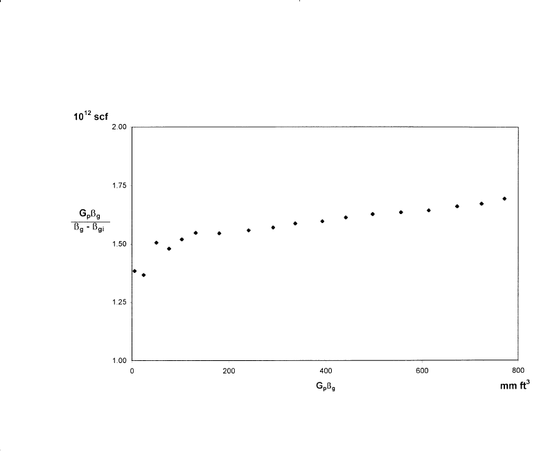
Step 3. A plot of G
p
B
g
/(B
g
- B
gi
) vs. G
p
B
g
showed an upward curvature,
as shown in Figure 13-10, indicating water influx.
WC ptt
enn
=-
Â
D (13- 24)
Gas Reservoirs 845
Reservoir Eng Hndbk Ch 13 2001-10-24 15:13 Page 845

Table 13-1
Havlena-Odeh Dry-Gas Reservoir Data for Example 13-4
Average
F/E
g
=
Reservoir E
g
= F =
SDp
n
Zt - t
n
G
p
B
g
Time Pressure (B
g
- B
gi
) ¥ 10
-6
(G
b
B
g
) ¥ 10
6
B
g
- B
gi
B
g
- B
gi
(months) (psi) (ft
3
/scf) (ft
3
) (10
6
) (10
12
)
0 2,883 0.0 — — —
2 2,881 4.0 5.5340 0.3536 1.3835
4 2,874 18.0 24.5967 0.4647 1.3665
6 2,866 34.0 51.1776 0.6487 1.5052
8 2,857 52.0 76.9246 0.7860 1.4793
10 2,849 68.0 103.3184 0.9306 1.5194
12 2,841 85.0 131.5371 1.0358 1.5475
14 2,826 116.5 180.0178 1.0315 1.5452
16 2,808 154.5 240.7764 1.0594 1.5584
18 2,794 185.5 291.3014 1.1485 1.5703
20 2,782 212.0 336.6281 1.2426 1.5879
22 2,767 246.0 392.8592 1.2905 1.5970
24 2,755 273.5 441.3134 1.3702 1.6136
26 2,741 305.5 497.2907 1.4219 1.6278
28 2,726 340.0 556.1110 1.4672 1.6356
30 2,712 373.5 613.6513 1.5174 1.6430
32 2,699 405.0 672.5969 1.5714 1.6607
34 2,688 432.5 723.0868 1.6332 1.6719
36 2,667 455.5 771.4902 1.7016 1.6937
Step 4. Assuming a linear water influx, plot G
p
B
g
/(B
g
- B
gi
) versus
as shown in Figure 13-11.
Step 5. As evident from Figure 13-11, the necessary straight-line relation-
ship is regarded as satisfactory evidence of the presence of linear
aquifer.
Step 6. From Figure 13-11, determine the original gas in place G and the
linear water influx constant C as:
G = 1.325 ¥ 10
12
scf
C = 212.7 ¥ 10
3
ft
3
/psi
Dptt BB
nnggi
-
[]
-
Â
()
846 Reservoir Engineering Handbook
Reservoir Eng Hndbk Ch 13 2001-10-24 15:13 Page 846
ABNORMALLY PRESSURED GAS RESERVOIRS
Hammerlindl (1971) pointed out that in abnormally high-pressure vol-
umetric gas reservoirs, two distinct slopes are evident when the plot of
p/z versus G
p
is used to predict reserves because of the formation and
fluid compressibility effects as shown in Figure 13-12. The final slope of
the p/z plot is steeper than the initial slope; consequently, reserve esti-
mates based on the early life portion of the curve are erroneously high.
The initial slope is due to gas expansion and significant pressure mainte-
nance brought about by formation compaction, crystal expansion, and
water expansion. At approximately normal pressure gradient, the forma-
tion compaction is essentially complete and the reservoir assumes the
characteristics of a normal gas expansion reservoir. This accounts for the
second slope. Most early decisions are made based on the early life
extrapolation of the p/z plot; therefore, the effects of hydrocarbon pore
volume change on reserve estimates, productivity, and abandonment
pressure must be understood.
Gas Reservoirs 847
Figure 13-10. Indication of the water influx.
Reservoir Eng Hndbk Ch 13 2001-10-24 15:13 Page 847
