Tarek Ahmed. Reservoir engineering handbook
Подождите немного. Документ загружается.

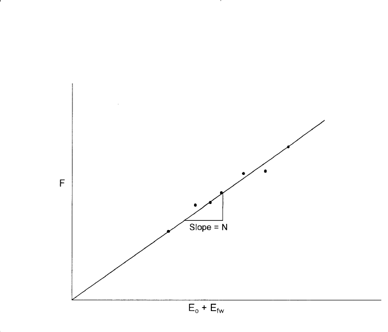
This interpretation technique is useful in that, if the linear relationship
is expected for the reservoir and yet the actual plot turns out to be non-
linear, then this deviation can itself be diagnostic in determining the actu-
al drive mechanisms in the reservoir.
A linear plot of the underground withdrawal F versus (E
o
+ E
f,w
) indi-
cates that the field is producing under volumetric performance, i.e., no
water influx, and strictly by pressure depletion and fluid expansion. On
the other hand, a nonlinear plot indicates that the reservoir should be
characterized as a water-drive reservoir.
Example 11-3
The Virginia Hills Beaverhill Lake field is a volumetric undersaturated
reservoir. Volumetric calculations indicate the reservoir contains 270.6
758 Reservoir Engineering Handbook
Figure 11-17. Underground withdrawal vs. E
o
+ E
fw
.
Reservoir Eng Hndbk Ch 11 2001-10-25 15:59 Page 758

MMSTB of oil initially in place. The initial reservoir pressure is 3685
psi. The following additional data is available:
S
wi
= 24% c
w
= 3.62 × 10
−6
psi
−1
c
f
= 4.95 × 10
−6
psi
−1
B
w
= 1.0 bbl/STB p
b
= 1500 psi
The field production and PVT data are summarized below:
Volumetric No. of B
o
N
p
W
p
Average Pressure producing wells bbl/STB MSTB MSTB
3685 1 1.3102 0 0
3680 2 1.3104 20.481 0
3676 2 1.3104 34.750 0
3667 3 1.3105 78.557 0
3664 4 1.3105 101.846 0
3640 19 1.3109 215.681 0
3605 25 1.3116 364.613 0
3567 36 1.3122 542.985 0.159
3515 48 1.3128 841.591 0.805
3448 59 1.3130 1273.530 2.579
3360 59 1.3150 1691.887 5.008
3275 61 1.3160 2127.077 6.500
3188 61 1.3170 2575.330 8.000
Calculate the initial oil in place by using the MBE and compare with
the volumetric estimate of N.
Solution
Step 1. Calculate the initial water and rock expansion term E
f,w
from
Equation 11-37:
E
f,w
= 10.0 × 10
−6
(3685 − p
–
r
)
Ep
fw,
.
.(.).
.
=
×+×
−
−−
1 3102
362 10 024 495 10
1024
66
∆
Oil Recovery Mechanisms and the Material Balance Equation 759
Reservoir Eng Hndbk Ch 11 2001-10-25 15:59 Page 759

Step 2. Construct the following table:
F, Mbbl E
o
, bbl/STB
p
–
r
, psi Equation 10-35 Equation 10-36 ∆pE
f, w
E
o
+ E
f, w
3685 — — 0 0 —
3680 26.84 0.0002 5 50 × 10
−6
0.00025
3676 45.54 0.0002 9 90 × 10
−6
0.00029
3667 102.95 0.0003 18 180 × 10
−6
0.00048
3664 133.47 0.0003 21 210 × 10
−6
0.00051
3640 282.74 0.0007 45 450 × 10
−6
0.00115
3605 478.23 0.0014 80 800 × 10
−6
0.00220
3567 712.66 0.0020 118 1180 × 10
−6
0.00318
3515 1,105.65 0.0026 170 1700 × 10
−6
0.00430
3448 1,674.72 0.0028 237 2370 × 10
−6
0.00517
3360 2,229.84 0.0048 325 3250 × 10
−6
0.00805
3275 2,805.73 0.0058 410 4100 × 10
−6
0.00990
3188 3,399.71 0.0068 497 4970 × 10
−6
0.01170
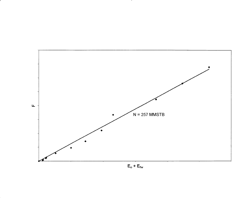
Step 3. Plot the underground withdrawal term F against the expansion
term (E
o
+ E
f,w
) on a Cartesian scale, as shown in Figure 11-18).
Step 4. Draw the best straight line through the points and determine the
slope of the line and the volume of the active initial oil in place as:
N = 257 MMSTB
It should be noted that the value of the initial oil in place as deter-
mined from the MBE is referred to as the effective or active initial oil in
place. This value is usually smaller than that of the volumetric estimate
due to oil being trapped in undrained fault compartments or low-perme-
ability regions of the reservoir.
Case 2. Volumetric Saturated-Oil Reservoirs
An oil reservoir that originally exists at its bubble-point pressure is
referred to as a saturated oil reservoir. The main driving mechanism in
this type of reservoir results from the liberation and expansion of the
solution gas as the pressure drops below the bubble-point pressure. The
only unknown in a volumetric saturated-oil reservoir is the initial oil in
place N. Assuming that the water and rock expansion term E
f,w
is negligi-
760 Reservoir Engineering Handbook
Reservoir Eng Hndbk Ch 11 2001-10-25 15:59 Page 760
ble in comparison with the expansion of solution gas, Equation 11-32 can
be simplified as:
F = N E
o
(11-38)
where the underground withdrawal F and the oil expansion E
o
were
defined previously by Equations 11-26 and 11-28 or Equations 11-27 and
11-29 to give:
F = N
p
[B
t
+ (R
p
− R
si
) B
g
] + W
p
B
w
E
o
= B
t
− B
ti
Equation 11-38 indicates that a plot of the underground withdrawal F,
evaluated by using the actual reservoir production data, as a function of
the fluid expansion term E
o
, should result in a straight line going through
the origin with a slope of N.
The above interpretation technique is useful in that, if a simple linear
relationship such as Equation 11-38 is expected for a reservoir and yet the
actual plot turns out to be nonlinear, then this deviation can itself be diag-
nostic in determining the actual drive mechanisms in the reservoir. For
Oil Recovery Mechanisms and the Material Balance Equation 761
Figure 11-18. F vs. (E
o
+ E
fw
) for Example 11-3.
Reservoir Eng Hndbk Ch 11 2001-10-25 15:59 Page 761

instance, Equation 11-38 may turn out to be nonlinear because there is an
unsuspected water influx into the reservoir helping to maintain the pressure.
Case 3. Gas-Cap-Drive Reservoirs
For a reservoir in which the expansion of the gas-cap gas is the pre-
dominant driving mechanism and assuming that the natural water influx
is negligible (W
e
= 0), the effect of water and pore compressibilities can
be considered negligible. Under these conditions, the Havlena-Odeh
material balance can be expressed as:
F = N [E
o
+ m E
g
] (11-39)
where E
g
is defined by Equation 11-30 as:
E
g
= B
oi
[(B
g
/B
gi
) − 1]
The way in which Equation 11-39 can be used depends on the number
of unknowns in the equation. There are three possible unknowns in
Equation 11-39:
• N is unknown, m is known
• m is unknown, N is known
• N and m are unknown
The practical use of Equation 11-39 in determining the three possible
unknowns is presented below:
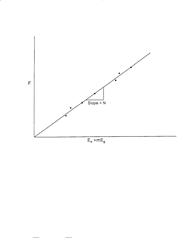
a. Unknown N, known m:
Equation 11-39 indicates that a plot of F versus (E
o
+ m E
g
) on a
Cartesian scale would produce a straight line through the origin with a
slope of N, as shown in Figure 11-19. In making the plot, the under-
ground withdrawal F can be calculated at various times as a function
of the production terms N
p
and R
p
.
Conclusion: N = Slope
b. Unknown m, known N:
Equation 11-39 can be rearranged as an equation of straight line, to give:
F
N
EmE
og
−
= (11- 40)
762 Reservoir Engineering Handbook
Reservoir Eng Hndbk Ch 11 2001-10-25 15:59 Page 762
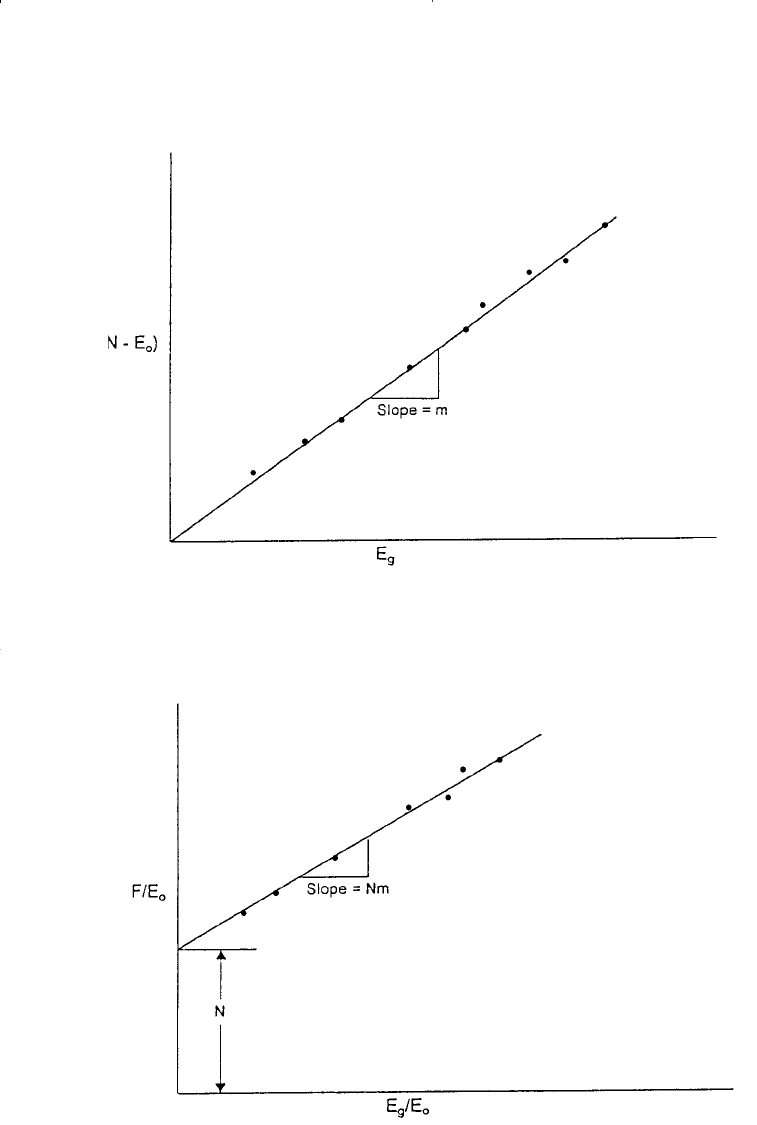
The above relationship shows that a plot of the term (F/N − E
o
) versus
E
g
would produce a straight line with a slope of m. One advantage of
this particular arrangement is that the straight line must pass through
the origin which, therefore, acts as a control point. Figure 11-20 shows
an illustration of such a plot.
Conclusion: m = Slope
c. N and m are Unknown
If there is uncertainty in both the values of N and m, Equation 11-39
can be re-expressed as:
A plot of F/E
o
versus E
g
/E
o
should then be linear with intercept N and
slope mN. This plot is illustrated in Figure 11-21.
Conclusions: N = intercept
mN = slope
m = slope/intercept
F
E
NmN
E
E
o
g
o
=+
(11- 41)
Oil Recovery Mechanisms and the Material Balance Equation 763
Figure 11-19. F vs. E
o
+ mE
g
.
Reservoir Eng Hndbk Ch 11 2001-10-25 15:59 Page 763
764 Reservoir Engineering Handbook
Figure 11-20. (F/N − E
o
) vs. E
g
.
Figure 11-21. F/E
o
vs. E
g
/E
o
.
Reservoir Eng Hndbk Ch 11 2001-10-25 15:59 Page 764

Example 11-4
1
The production history and the PVT data of a gas-cap-drive reservoir
are given below:
p
–
N
p
G
p
B
t
B
g
Date psi MSTB Mscf bbl/STB bbl/scf
5/1/89 4415 — — 1.6291 0.00077
1/1/91 3875 492.5 751.3 1.6839 0.00079
1/1/92 3315 1015.7 2409.6 1.7835 0.00087
1/1/93 2845 1322.5 3901.6 1.9110 0.00099
The initial gas solubility R
si
is 975 scf/STB. Estimate the initial oil and
gas in place.
Solution
Step 1. Calculate the cumulative produced gas-oil ratio R
p
G
p
N
p
R
p
= G
p
/N
p
p
–
Mscf MSTB scf/STB
4415 — — —
3875 751.3 492.5 1525
3315 2409.6 1015.7 2372
2845 3901.6 1322.5 2950
Step 2. Calculate F, E
o
, and E
g
:
pF E
o
E
g
3875 2.04 × 10
6
0.0548 0.0529
3315 8.77 × 10
6
0.1540 0.2220
2845 17.05 × 10
6
0.2820 0.4720
Step 3. Calculate F/E
o
and E
g
/E
o
p F/E
o
E
g
/E
o
3875 3.72 × 10
7
0.96
3315 5.69 × 10
7
1.44
2845 6.00 × 10
7
1.67
Oil Recovery Mechanisms and the Material Balance Equation 765
1
After Economides, M., and Hill, D., Petroleum Production Systems, Prentice Hall, 1993.
Reservoir Eng Hndbk Ch 11 2001-10-25 15:59 Page 765
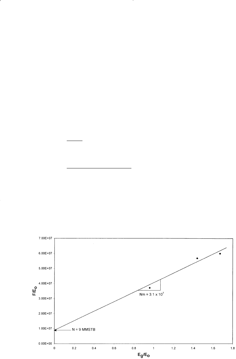
Step 4. Plot (F/E
o
) versus (E
g
/E
o
) as shown in Figure 11-22 to give:
• Intercept = N = 9 MMSTB
• Slope = N m = 3.1 × 10⁷
Step 5. Calculate m:
m = 3.1 × 10
7
/(9 × 10
6
) = 3.44
Step 6. Calculate initial gas in place G:
Case 4. Water-Drive Reservoirs
In a water-drive reservoir, identifying the type of the aquifer and char-
acterizing its properties are perhaps the most challenging tasks involved
in conducting a reservoir engineering study. Yet, without an accurate
m
GB
NB
G MMMscf
gi
oi
=
=
×
=
( . )( )( . )
.
3 44 9 10 1 6291
0 00077
66
6
766 Reservoir Engineering Handbook
Figure 11-22. Calculation of m and N for Example 11-4.
Reservoir Eng Hndbk Ch 11 2001-10-25 15:59 Page 766

description of the aquifer, future reservoir performance and management
cannot be properly evaluated.
The full MBE can be expressed again as:
F = N (E
o
+ m E
g
+ E
f,w
) + W
e
Dake (1978) points out that the term E
f,w
can frequently be neglected
in water-drive reservoirs. This is not only for the usual reason that the
water and pore compressibilities are small, but also because a water
influx helps to maintain the reservoir pressure and, therefore, the ∆p
appearing in the E
f,w
term is reduced, or
F = N (E
o
+ m E
g
) + W
e
(11 - 42)
If, in addition, the reservoir has initial gas cap, then Equation 11-42
can be further reduced to:
F = N E
o
+ W
e
(11 - 43)
Dake (1978) points out that in attempting to use the above two equa-
tions to match the production and pressure history of a reservoir, the
greatest uncertainty is always the determination of the water influx W
e
.
In fact, in order to calculate the influx the engineer is confronted with
what is inherently the greatest uncertainty in the whole subject of reser-
voir engineering. The reason is that the calculation of W
e
requires a
mathematical model which itself relies on the knowledge of aquifer prop-
erties. These, however, are seldom measured since wells are not deliber-
ately drilled into the aquifer to obtain such information.
For a water-drive reservoir with no gas cap, Equation 11-43 can be
rearranged and expressed as:
Several water influx models have been described in Chapter 10,
including the:
• Pot-aquifer model
• Schilthuis steady-state method
• Van Everdingen-Hurst model
F
E
N
W
E
o
e
o
=+ (11- 44)
Oil Recovery Mechanisms and the Material Balance Equation 767
Reservoir Eng Hndbk Ch 11 2001-10-25 15:59 Page 767
