Tarek Ahmed. Reservoir engineering handbook
Подождите немного. Документ загружается.


258 Reservoir Engineering Handbook
0.01 0.05 0.1 0.2 0.5 1 2 5 10 20 30 40 50
50
60 70 80 90 95 98 99 99.8 99.9 99.99
1
2
3
4
5
6
7
8
9
1
2
3
4
5
6
7
8
9
10
1
2
3
4
5
6
7
8
9
1
2
3
4
5
6
7
8
9
10
0.010.050.10.20.525102030406070809095989999.9899.999.99 1
Figure 4-29. Probability-log scale.
Reservoir Eng Hndbk Ch 04b 2001-10-24 09:46 Page 258

Solution
Step 1. Arrange the entire permeability data in a descending order and
calculate % of thickness with greater permeability as shown
below:
kh
md ft h with greater k % of h with greater k
435 2 0 0
254 2 2 3.6
196 2 4 7.1
172 3 6 10.7
166 2 9 16.1
158 2 11 19.6
153 2 13 23.2
147 2 15 26.8
128 1 17 30.4
105 2 18 32.1
100 1 20 35.7
91 2.5 21 37.5
90 2.5 23.5 42.0
83 2 26 46.4
72 1.5 28 50
62 2 29.5 52.7
49 6.5 31.5 56.3
44 2 38 67.9
40 2 40 71.4
35 2 42 75.0
32 2 44 78.6
30 2 46 82.1
28 2 48 85.7
27 2 50 89.3
20 2 52 92.9
9 2 54 96.4
Total = 56¢
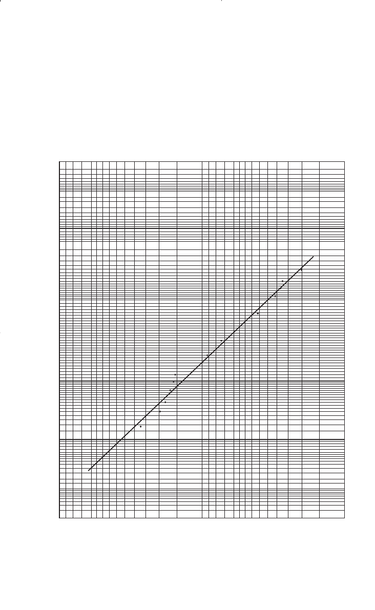
Step 2. Plot the permeability versus % of thickness with greater k on a
log-probability scale as shown in Figure 4-30 and read
k
50
= 68 md
k
84.1
= 29.5
Fundamentals of Rock Properties 259
Reservoir Eng Hndbk Ch 04b 2001-10-24 09:46 Page 259
260 Reservoir Engineering Handbook
0.01 0.05 0.1 0.2 0.5 1 2 5 10 20 30 40 50
50
60 70 80 90 95 98 99 99.8 99.9 99.99
1
2
3
4
5
6
7
8
9
1
2
3
4
5
6
7
8
9
10
1
2
3
4
5
6
7
8
9
1
2
3
4
5
6
7
8
9
10
0.010.050.10.20.525102030406070809095989999.899.999.99 1
% of Thickness with Greater k
Permeability, k
Figure 4-30. % of h vs. k.
Reservoir Eng Hndbk Ch 04b 2001-10-24 09:46 Page 260

Step 3. Calculate V by applying Equation 4-70.
It should be noted that if all the permeabilities are equal, the numerator
or Equation 4-70 would be zero, and the V would also be zero. This
would be the case for a completely homogeneous system. The Dykstra-
Parsons method is commonly referred to as a Permeability Ordering
Technique.
In water flooding calculations, it is frequently desired to divide the
reservoir into layers that have equal thickness and different permeability.
The log-probability scale can be used in this case to assign the perme-
ability scale into equal percent increments and to read the corresponding
permeability at the midpoint of each interval.
Example 4-19
Using the data given in Example 4-18, determine the average layer
permeability for a 10-layered system, assuming a uniform porosity.
Solution
Using the Dykstra-Parsons’s log-probability plot as shown in Figure 4-
30, determine the permeability for the 10-layered system as follows:
Layer % Probability k, md
1 5 265
2 15 160
3 25 120
435 94
545 76
655 60
765 49
875 39
985 29
10 95 18
Although permeability and porosity are not related in a strict technical
sense, they should correlate in rock of similar lithology and pore size distri-
V =
-
=
68 29 5
68
057
.
.
Fundamentals of Rock Properties 261
Reservoir Eng Hndbk Ch 04b 2001-10-24 09:46 Page 261

bution. In many cases, the logarithm of permeability versus porosity plots
is frequently made and the best straight line is drawn through the points.
Lorenz Coefficient L
Schmalz and Rahme (1950) introduced a single parameter that
describes the degree of heterogeneity within a pay zone section. The term
is called Lorenz coefficient and varies between zero, for a completely
homogeneous system, to one for a completely heterogeneous system.
The following steps summarize the methodology of calculating Lorenz
coefficient:
Step 1. Arrange all the available permeability values in a descending
order.
Step 2. Calculate the cumulative permeability capacity Skh and cumula-
tive volume capacity Sfh.
Step 3. Normalize both cumulative capacities such that each cumulative
capacity ranges from 0 to 1.
Step 4. Plot the normalized cumulative permeability capacity versus the
normalized cumulative volume capacity on a Cartesian scale.
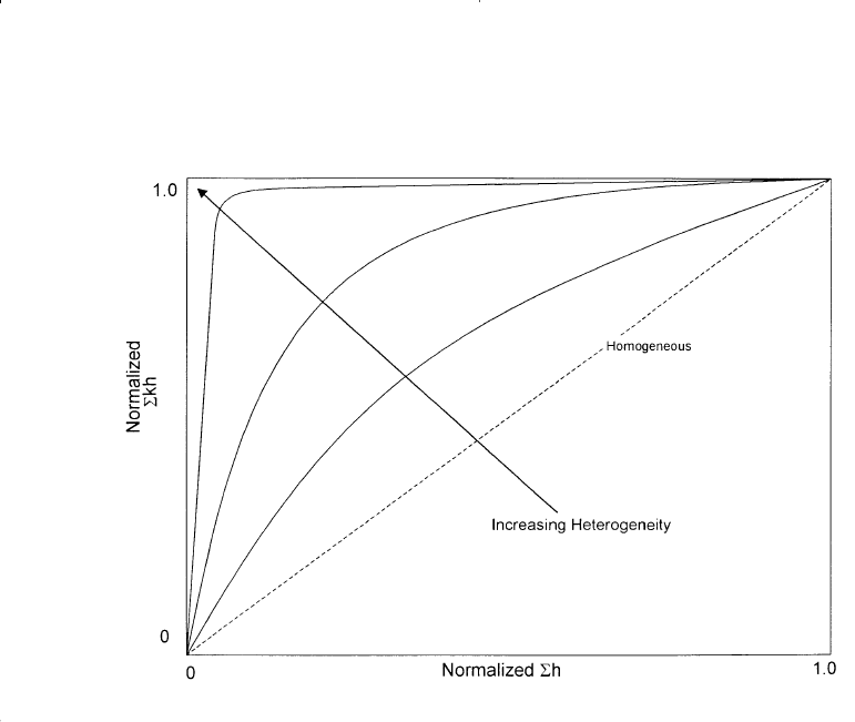
Figure 4-31 shows an illustration of the flow capacity distribution. A
completely uniform system would have all permeabilities equal, and a
plot of the normalized Skh versus Sfh would be a straight line. Figure
4-31 indicates that as the degree of contrast between high and low values
of permeability increases the plot exhibits greater concavity toward the
upper left corner. This would indicate more heterogeneity, i.e., the severi-
ty of deviation from a straight line is an indication of the degree of het-
erogeneity. The plot can be used to describe the reservoir heterogeneity
quantitatively by calculating the Lorenz coefficient. The coefficient is
defined by the following expression:
L
Area above the straight line
Area below the straight line
= (4 - 71)
262 Reservoir Engineering Handbook
Reservoir Eng Hndbk Ch 04b 2001-10-24 09:46 Page 262
where the Lorenz coefficient L can vary between 0 and 1.
0 = completely homogeneous
1 = completely heterogeneous
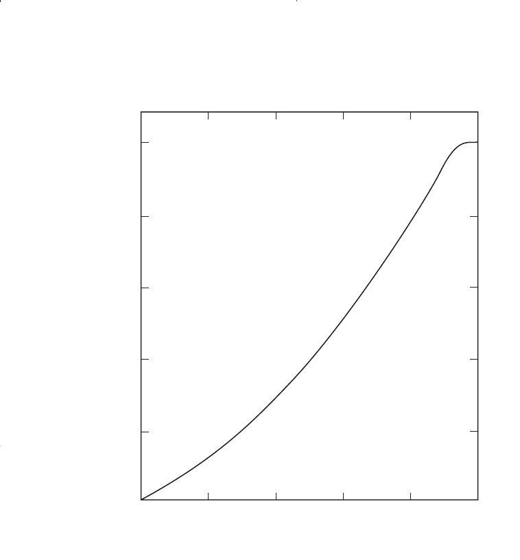
Figure 4-32 shows the relation of the permeability variation V and
Lorenz coefficient L for log-normal permeability distributions as pro-
posed by Warren and Price (1961). This relationship can be expressed
mathematically by the following two expressions:
Lorenz coefficient in terms of permeability variation:
L = 0.0116356 + 0.339794V + 1.066405V
2
- 0.3852407V
3
(4-72)
Permeability variation in terms of Lorenz coefficient:
V =-5.05971(10
-4
) + 1.747525L - 1.468855 L
2
+ 0.701023 L
3
(4-73)
Fundamentals of Rock Properties 263
Figure 4-31. Normalized flow capacity.
Reservoir Eng Hndbk Ch 04b 2001-10-24 09:46 Page 263
The above two expressions are applicable between 0 < L < 1 and 0 <
V < 1.
Example 4-20
Using the data given in Example 4-18, calculate the Lorenz coefficient
assuming a uniform porosity.
Solution
Step 1. Tabulate the permeability data in a descending order and calculate
the normalized Skh and Sh as shown below:
264 Reservoir Engineering Handbook
0
0
.2 .4 .6 .8 1.0
.2
.4
.6
.8
1.0
Variation, V
Lorenz Coefficient
Figure 4-32. Correlation of Lorenz coefficient and permeability variation.
Reservoir Eng Hndbk Ch 04b 2001-10-24 09:46 Page 264

k, md h, ft kh Skh Skh/5646.5 Sh Sh/56
435 2 870 870 0.154 2 0.036
254 2 508 1378 0.244 4 0.071
196 2 392 1770 0.313 6 0.107
172 3 516 2286 0.405 9 0.161
166 2 332 2618 0.464 11 0.196
158 2 316 2934 0.520 13 0.232
153 2 306 3240 0.574 15 0.268
147 2 294 3534 0.626 17 0.304
128 1 128 3662 0.649 18 0.321
105 2 210 3872 0.686 20 0.357
100 1 100 3972 0.703 21 0.375
91 2.5 227.5 4199.5 0.744 23.5 0.420
90 2.5 225 4424.5 0.784 26 0.464
83 2 166 4590.5 0.813 28 0.50
72 1.5 108 4698.5 0.832 29.5 0.527
62 2 124 4822.5 0.854 31.5 0.563
49 6.5 294 5116.5 0.906 38.0 0.679
44 2 88 5204.5 0.922 40.0 0.714
40 2 80 5284.5 0.936 42 0.750
35 2 70 5354.4 0.948 44 0.786
32 2 64 5418.5 0.960 46 0.821
30 2 60 5478.5 0.970 48 0.857
28 2 56 5534.5 0.980 50 0.893
27 2 54 5588.5 0.990 52 0.929
20 2 40 5628.5 0.997 54 0.964
9 2 18 5646.5 1.000 56 1.000
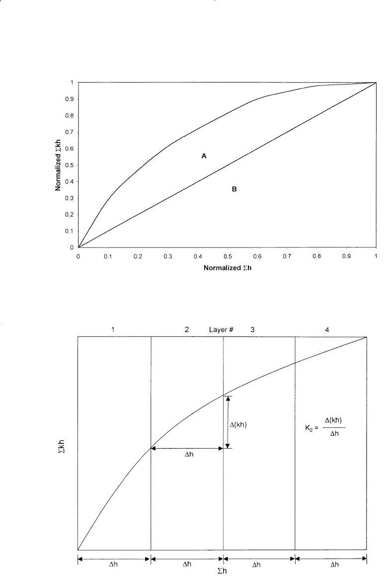
Step 2. Plot the normalized capacities on a Cartesian scale as shown in
Figure 4-33.
Step 3. Calculate the Lorenz coefficient by dividing the area above the
straight line (area A) by the area under the straight line (area B)
to give:
L = 0.42
A plot of the cumulative permeability capacity Skh versus Sh (without
normalization) is commonly constructed, as shown in Figure 4-34, and
used to assign average permeability values for a selected number of
reservoir layers. If the intervals of the thickness are chosen, as shown in
Figure 4-34, then the average values of permeability for each thickness
interval (layer) can be calculated by dividing the incremental (kh) by the
incremental thickness.
Fundamentals of Rock Properties 265
Reservoir Eng Hndbk Ch 04b 2001-10-24 09:46 Page 265
266 Reservoir Engineering Handbook
Figure 4-33. Normalized flow capacity for Example 4-20.
Figure 4-34. Cumulative permeability capacity vs. cumulative thickness.
Reservoir Eng Hndbk Ch 04b 2001-10-24 09:46 Page 266

It should be noted that it is not necessary that equal thickness sections
be chosen. They may be selected at irregular increments as desired.
There are also some advantages of selecting layer properties so that each
layer has the same permeability thickness product.
Example 4-21
Using the data given in Example 4-18, calculate the average perme-
ability for a 10-layered system reservoir. Compare the results with those
of the Dykstra-Parsons method.
Solution
Step 1. Using the calculated values of Skh and Sh of Example 4-20, plot
Skh versus Sh on a Cartesian coordinate as shown in Figure 4-35.
Step 2. Divide the x-axis into 10 equal segments*, each with 5.6 ft.
Step 3. Calculate the average permeability k
–
for each interval, to give:
Layer k
–
k
–
from Dykstra-Parsons, Example 4-19
1 289 265
2 196.4 160
3 142.9 120
4 107.1 94
5 83.9 76
6 67.9 60
7 44.6 49
8 35.7 39
9 32.1 29
10 17.2 18
The permeability sequencing (ordering) methods of zonation do not
consider the physical location of the rocks with the vertical column. All
the data are considered to be a statistical sampling, which will describe
the statistical distribution of permeability, porosity, and thickness within
the reservoir. All the values of equal permeability are presumed to be in
communication with each other.
Fundamentals of Rock Properties 267
*It should be noted that the 56 feet do not equal the reservoir net thickness. It essentially
represents the cumulative thickness of the core samples.
Reservoir Eng Hndbk Ch 04b 2001-10-24 09:46 Page 267
