Szilas A.P. Production and transport of oil and gas, Gathering and Transportation
Подождите немного. Документ загружается.


I80
7
PII’I
1
IN1
TKANSI’OKIATION
01
011
Let usexpresstheformula Ap/,/[~.(~ash/,,and substitute
Eq.
1.1
-
I
tocxprcss
Aprl.
then we obtain
where the hydraulic.
or
friction gradient is
q
4
Substituting formula
I:=
--and the
q=9.81
value we find that
dfn
~~~~
7.4--
2
7.4-
3
7.4
~
4
Each term
of
Eq. 7.4-
1
permits a twofold physical interpretation. They may be
considered,
on
the one hand, as energy contents
of
a liquid body
of
unit weight,
in
J/N
units, and on the other, as liquid column heights
in
m, the density of thc liquid
being
p.
The
p/pg
term the specific external potential energy is equivalent
to
pressure head
h
and the specific kinetic energy
u2/2g
to
velocity head
h,,.
while the specific internal
potential energy
to
the geodetic height, denoted by
z.
Neglecting the change
in
the
specific volume
of
the flowing liquid, due
to
the change of pressure.
in
case
of
isothermal flow
u1
=
u2,
i.e. the velocity head difference between two pipeline cross
sections is zero.
It
means, that
Eq.
7.4-
1
can be expressed
in
the following, simpler
form:
7.4
-
5
In isothermal flow
(/
is constant, and therefore the specific energy content of the
flowing oil, along the pipeline linearly decreases along the pipeline.
On
horizontal
terrains
z1
=zz,
and thus Eq. 7.4-5 is further simplified, as
WI
-
W,
=
hl
-
h,
+
~1-
Z,
=
(/Ix.
h,=h,
-tJ,,
7.4
-
6
i.e. the pressure head
of
oil,
flowing in the pipeline, decreases linearly with distance
along the pipeline.
The alteration
of
the components, characterizing the specific energy content,
in
ease
of
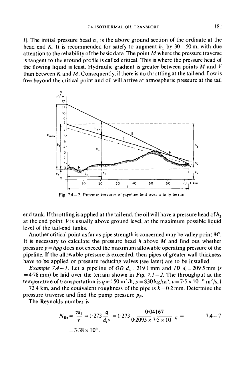
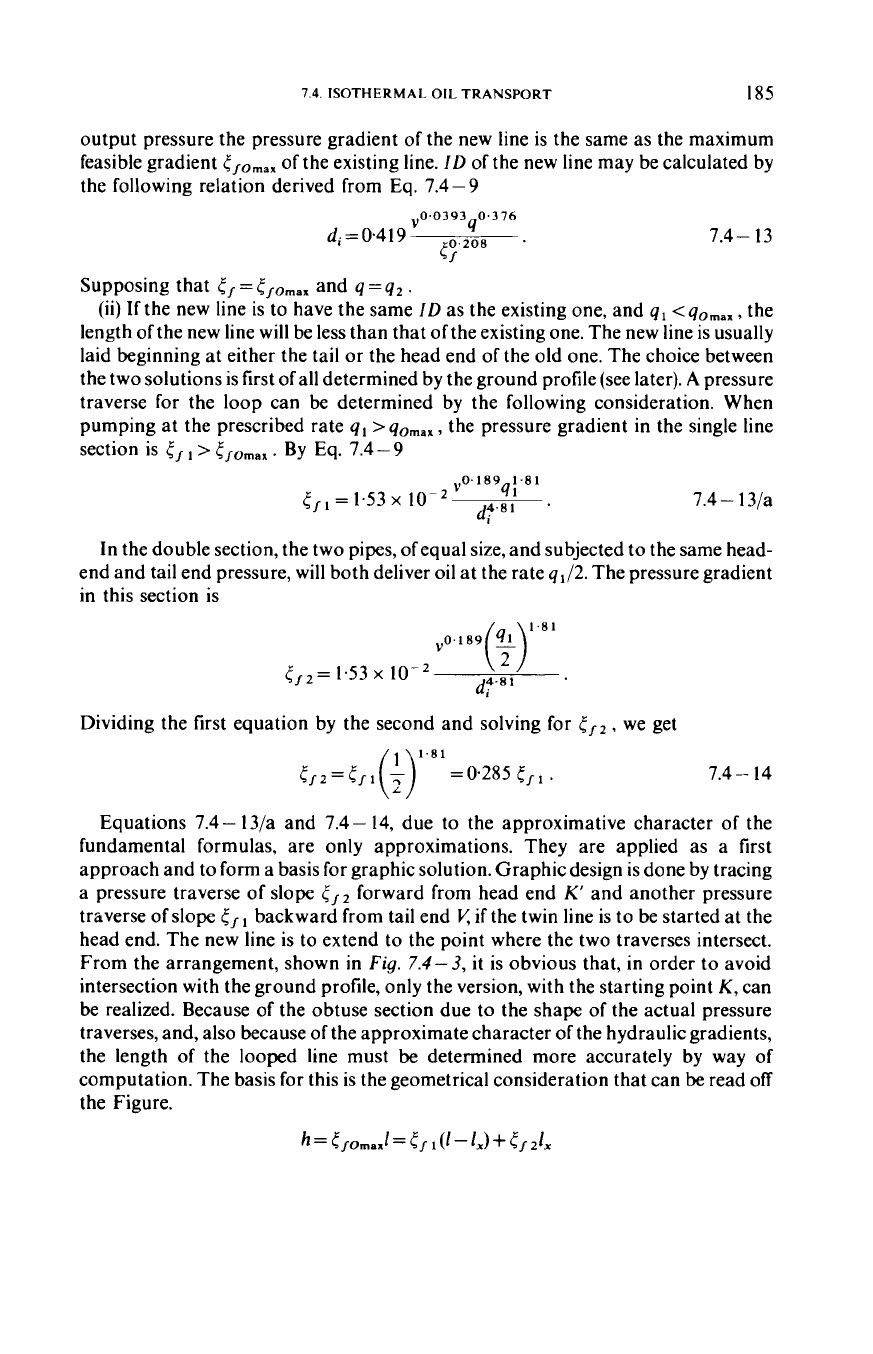
pipelines laid on hilly terrains, is shown in
Fig.
7.4-2.
The pressure head
h,
at head end
K
required
to
mooe
oil
at
aflow
rute q
through
pipe of
ID
d
laid over a given terrain can be determined as follows. Using Eq. 7.4
-
3
the gradient
r,
is calculated.
A
line with a slope corresponding
to
this gradient
is
drawn from tail end
V
to
head end
K.
This is the pressure or piezometric traverse
I’
in
Fig.
7.4-2.
If
this line intersects the ground profile, then the pressure traverse
must be displaced parallel to itself until
it
will merely touch the ground profile (line
7.4.
ISOTHERMAL
OIL
TRANSPORT
IS1
I).
The initial pressure head
h,
is the above ground section of the ordinate at the
head end
K.
It is recommended for satefy to augment
h,
by 30-50m, with due
attention to the reliability of the basic data. The point
M
where the pressure traverse
is tangent to the ground profile is called critical. This is where the pressure head of
the flowing liquid is least. Hydraulic gradient is greater between points
M
and
V
than between
K
and M. Consequently,
if
there is no throttling at the tail end, flow is
free beyond the critical point and oil will arrive at atmospheric pressure at the tail
h
102m
I
20
30
,
LO
50
60
70
ll,km
I
'0
Fig.
7.4-
2.
Pressure traverse
of
pipeline laid
over
a
hilly
terrain
end tank.
If
throttling is applied at the tail end, the
oil
will have a pressure head
of
h,
at the end point: Vis usually above ground level, at the maximum possible liquid
level of the tail-end tanks.
Another critical point as far as pipe strength is concerned may be valley point
M'.
It
is necessary to calculate the pressure head
h
above
M
and find out whether
pressure
p=
hpg
does not exceed the maximum allowable operating pressure of the
pipeline.
If
the allowable pressure is exceeded, then pipes of greater wall thickness
have
to
be applied
or
pressure reducing valves (see later) are to
be
installed.
Example
7.4-1.
Let a pipeline of
OD
d,=219.1 mm and
ID
di=209.5mm
(s
=4.78 mm) be laid over the terrain shown in
Fig.
7.1
-2.
The throughput at the
temperature
of
transportation is
q
=
150
m3/h;
p
=
830 kg/m3;
v
=
7.5
x
10
~ m2/s;
1
=
72.4
km,
and the equivalent roughness of the pipe is
k
=0.2 mm. Determine the
pressure traverse and find the pump pressure
pp.
The Reynolds number is
7.4
-
7
-
od.
4
0.04167
N,,
=
=
1.273
-
=
1.273
V
di
v
0.2095
x
7.5
x
-
=3.38
x
lo4.
1x2
7
PIPFI.INT.
TRANSPORTATION
OF
011
Pipe relative roughness:
k
2x10
d, 0.2095
~
- -
=9.5x
10-4.
From the Colebrook formula
(Eq.
1.1
-7)
the friction factor is computed by
iteration
By
Eq.
7.4-4
the friction gradient
0.0253
x
0.04167'
0.20955
5,
=
0.00826
=
0.00899
m/m
The ordinate at
K
corresponding to the intercept of the pressure traverse traced
backwards from Vaccording
to
Eq.
7.4-
5
is
17;
=
h,.
+
cr/-(zK
-2")
=O
+
0.00899
x
72 400
+
83
=
734
m
.
where
8.3
m
is the geodetic-head difference
(z,
-z2)
between point
K
and
I/:
In
the
Figure. the pressure traverse
in
question is shown by dashed line
1'.
As
it
enters the
ground. the head-end pressure head actually required is higher:
it
is obtained by
displacing the pressure traverse parallel to itself. making
it
tangent to the ground
profile at the point
M.
Accordingly
h;
=
800
m.
For
safety, let us augment this by
40
m, giving
h,
=
800+40= 840
m. The pressure head of the pump to
be
installed at
point
K
should then,
be
pp
=
hKp~
=
840
x
830
x
9.8
1
=
6.84
M
Pa
Assuming that
pumping
station
c..ui.sts
only at
K
head end.
rho
qrratrst throughput
qfrhe
pipcline
can be determined
by
the following procedure. Let us plot above
the
ground profile at
K
the pressure head
h,,,
corresponding to the maximum
allowable operating pressure ofthe pipe
(Fig.
7.4-2).
Joining this point
with
V
(or
with
critical point
M,
if
there is one) we obtain a pressure traverse whose slope
corresponds
to
the maximum feasible pressure gradient
i,-Omax.
In
the knowledge
of
this latter, the maximum oil throughput,
qoma,
can be determined as follows.
Let the two constants
in
Eq.
1.1
-
10
be
a=O.194
and
h=0.189.
Then
i.
=
0.194Ni;"
'')
.
7.4
-
8
Introducing this into
Eq.
7.4-4
7.4
-
9
7.4-
10
whence
7.4.
ISOTHERMAL OIL TRANSPORT
I83
Introducing into Eq.
7.4
-
10
the graphically determined value of t,om;rx
=
5,
we
may calculate
qomax =q,
the maximum liquid throughput of the pipeline
if
the only
pump station is at the head end. The accuracy of the computation can be increased
of the value of the friction factor, obtained from Eq.
7.4
-
8,
is only considered
as
first
approximation, and then the computation is continued by applying Eq.
1.1
-
7,
i.e.
the Colebrook formula. Eq.
7.4-4,
similarly to the above by substituting the
relation
u
-
q,
and the
y
=
9.81,
respectively, may be simplified to the following form:
7.4-
1
I
where subscript
a
refers to the above calculated approximate values. Knowing the
value
qa
a more accurate Reynolds number, and from the Colebrook formula
1.1
-
7
a more accurate
AC
friction factor can be computed. From Eq.
7.4
-
I1
it
follows that
&q:
=
R,q:
2.q:
=
12.1
<,d;5
,
and from this relation the more accurately determined flow rate is
7.4- 12
The exact
qomax
value is obtained after further iterations.
Example
7.4
-
2.
Let us find the maximum throughput of the pipeline
characterized in Example
7.4-
I,
if
API standard pipe made of
X-42
steel is used,
and terrain belongs to category (a) characterized
in
Section
6.1
-
3,
that is, the safety
factor
k
=
1.3;
let
e=
1.
The pressure rating is calculated using Eq.
6.1
~
3.
From
Table
6.1
-
3,
aF
=
289
M
Pa, and hence by Eq.
6.1
-
2
289
1.3
aa,=
~
=222 x
lo6
Pa
The maximum allowable internal overpressure is
Ap
-
9.69
x
10'
pg
830~9.81
h;,,=
-
-
=1190m.
Let us reduce this value by
40m
for safety. Hence,
h,,,=
1190-40=
ll5Om.
Plotting
h,,,
at the point
K
and joining
it
with
V
we get pressure traverse
11.
Clear-
ly,
the pressure traverse passes above the critical ground-profile section, and the
safety reserve
of
pressure is sufficient also from this point of view. The maximum
pressure gradient is
1150-83
72
400
=
0.0
147
m/m
5,omax
=
184
7.
PIPELINE TRANSPORTATION
OF
011
The maximum liquid throughput by
Eq.7.4-
10
is
0.0147°'552
x
0.2095*""
=
0.0525
m3/s
=
(7.5
10
~
(y
I
04
qomar
= =
10.1
=
189
m3/h.
Considering
Eq. 7.4-7,
the Reynolds number based on this pumping rate is
=4a x
104
0.0525
N,,
=
1.273
0.2095
x
7.5
x
10
By Eq.
7.4
-
8
A,=0194 ~(4.25
x
lo4)
0"89=0.0259
and according to Eq.
1.1
-
7
From this relation, by applying a short iteration we obtain that
A,
=
0.0243
By Eq.
7.4- 12
qi
=
0.0522
~
=
0,0539
m3/s
=
194
m'/h
.
JZ
If, at this rate, we calculate again
N,,
,
and then
1,.
then we receive the previous
0.0243
value, i.e.
qi
=
qomax
.
(b)
Increasing
the
capacity
of
pipelines by looping
Even the maximum throughput
qomax
of
an existing pipeline may be insufficient
to transport the required
qo
rate. One
of
the possibilities
to
increase the transport
capacity
of
the existing pipe line is looping: a second line, a so-called twin line is laid
alongside the original pipeline and is jointed to it. The
twin
line may be
of
two types:
(i)
new line of same length as old line but usually of different diameter (complete
loop),
(ii)
new line shorter than old line but
of
the same
ID
(partial loop).
Exceptionally, pipelines, that are shorter than the original ones, but are
of
greater
internal diameter, are applied. The advantage of the shorter twin line
of
different
diameter,
as
compared to the full length twin line, is that the transfer capacity of the
system, by way of increasing its length may be further increased.
Solution
(i)
may be regarded as two independent pipelines with the size ofthe new
line chosen
so
as
to
deliver a flow of
q2
=
q,
-
qomax
under the original input pressure
h,,,
between the points
K
and
V
Owing
to
the identity of trace and of input and
7.4.
ISOTHERMAL
OIL
TRANSPORT
185
output pressure the pressure gradient of the new line is the same as the maximum
feasible gradient
(/Omax
of the existing line.
ID
of the new line may be calculated by
the following relation derived from Eq.
7.4-9
"0.0393 0.376
4
di=0-419
o,208
l/
7.4-
13
Supposing that
5
=
5
,-Omax
and
q
=
q2
.
(ii)
If the new line is to have the same
ID
as the existing one, and
q1
<qomax,
the
length of the new line will be less than that of the existing one. The new line is usually
laid beginning at either the tail
or
the head end of the old one. The choice between
the two solutions is first ofall determined by the ground profile (see later).
A
pressure
traverse for the loop can be determined by the following consideration. When
pumping at the prescribed rate
ql
>qomax,
the pressure gradient in the single line
section is
5
>
5
fOmax
. By Eq.
7.4
-
9
v0.189
1.81
7.4
-
13/a
In the double section, the two pipes,
of
equal size, and subjected to the same head-
end and tail end pressure, will both deliver oil at the rate
q1/2.
The pressure gradient
in this section is
41
5,
1
=
1.53
x
d4.81
.
Dividing the first equation by the second and solving for
rf
2,
we get
1.81
5/2=5/
l(;)
=
0.285
5,
I
7.4- 14
Equations
7.4-
13/a and
7.4- 14,
due to the approximative character
of
the
fundamental formulas, are only approximations. They are applied as a first
approach and
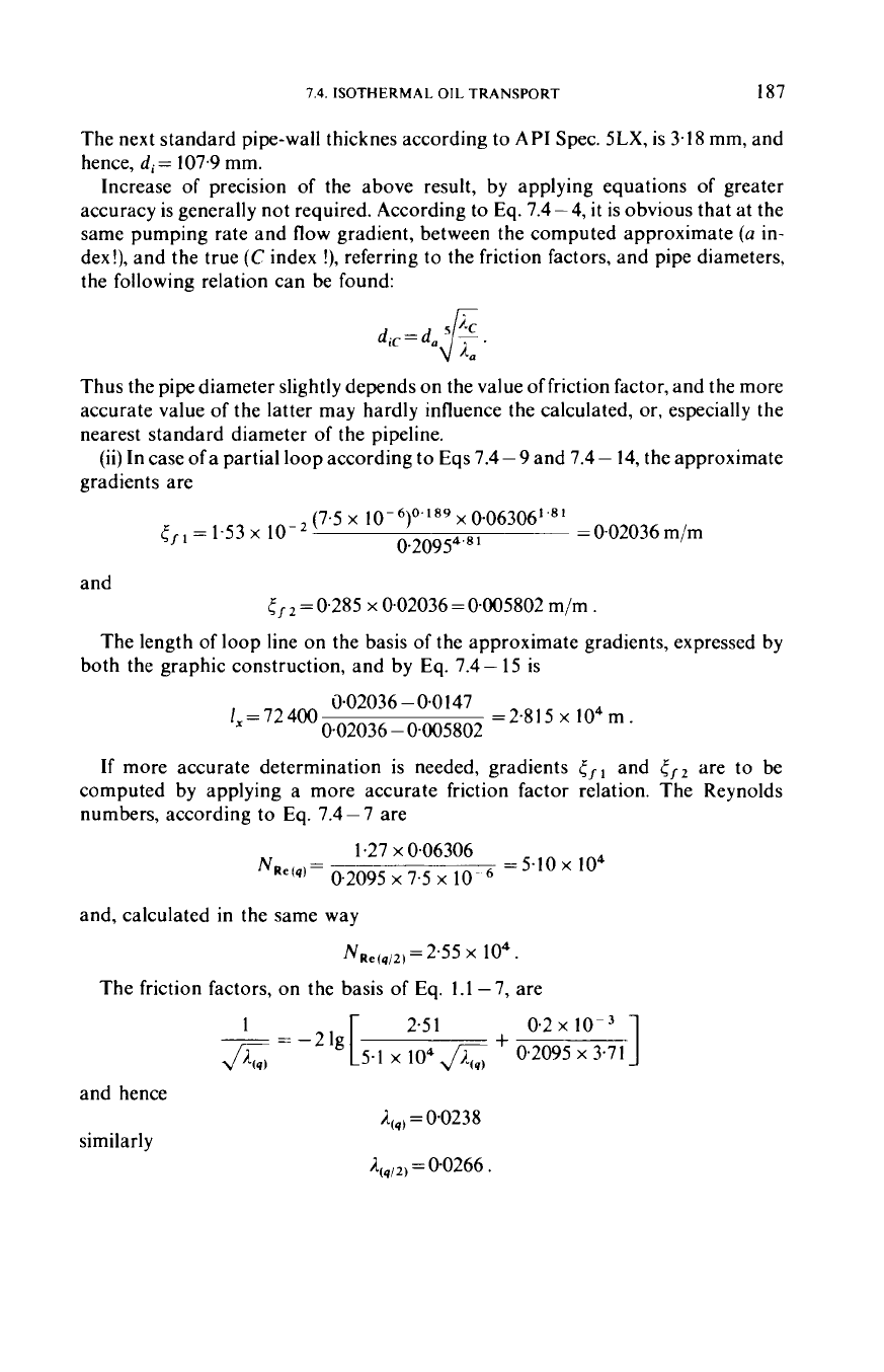
to
form a basis for graphic solution. Graphic design is done by tracing
a pressure traverse of slope
tf
forward from head end
K'
and another pressure
traverse of slope
5
backward from tail end
V,
if
the twin line is to be started at the
head end. The new line is to extend
to
the point where the two traverses intersect.
From the arrangement, shown in
Fig.
7.4-3,
it
is obvious that, in order to avoid
intersection with the ground profile, only the version, with the starting point
K,
can
be realized. Because of the obtuse section due
to
the shape
of
the actual pressure
traverses, and, also because
of
the approximate character of the hydraulic gradients,
the length
of
the looped line must be determined more accurately by way of
computation. The basis for this is the geometrical consideration that can
be
read
off
the Figure.
186
7.
PIPELINE TRANSPORTATION
OF
OIL
-
Fig.
7.4~-
3.
Pressure traverse
of
twin (looped) pipeline
and from this relation
5
f
I
-
5
fOmax
tfl-rfz
1,
=
1
7.4
-
15
The exact friction factor for the gradients at turbulent flow
in
the transition zone
may be computed by the Colebrook equation.
Example
7.4
-3.
Under the conditions stated
in
the previous example, existing
pipeline capacity is to be increased to
227
m3/h.
A
full
length and
a
short length loop
line are to be designed.
(i)
For
a complete loop,
q2
=
227- I94
=
33
m3/h
=O.O0917
m3/s.
By
Eq.
7.4-
13,
(7.5
x
10-6)0.0393
x(9.17 x
10-3)0.376
(1.47~
10-2)o'208
=0.108 m
d;
=
0.4
1
9
The next standard
API
pipe has
do=
114.3 mm
(=4 1/2
in.)
(see Table 6.1
-2).
For
X-42
grade steel, with reference to Example
7.4
-
2,
on,=
222
MPa.
By
Eq.
6.1
-3
dpd,
s=
-
- -
2eanr
9.69
x
lo6
x
0.1
143
2
x
1
x
222
x
lo6
=
04025
m
=
2.5
mrn
7.4.
ISOTHERMAL
OIL
TRANSPORT
187
The next standard pipe-wall thicknes according to
API
Spec.
5LX,
is
3.18
mm, and
hence,
di
=
107.9
mm.
Increase of precision of the above result, by applying equations of greater
accuracy is generally not required. According
to
Eq.
7.4
-
4,
it
is obvious that at the
same pumping rate and flow gradient, between the computed approximate
(a
in-
dex!), and the true
(C
index
!),
referring to the friction factors, and pipe diameters,
the following relation can be found:
Thus the pipe diameter slightly depends on the value of friction factor, and the more
accurate value of the latter may hardly influence the calculated,
or,
especially the
nearest standard diameter of the pipeline.
(ii)
In case of a partial loop according to
Eqs
7.4
-
9
and
7.4
-
14,
the approximate
gradients are
(7.5 x 10⁻⁶)0.'89 x 006306"81
0.20954'81
=
0.02036
m/m
=
1.53
x
and
5,
=
0.285
x
0.02036
=
0.005802
m/m .
The length of loop line on the basis of the approximate gradients, expressed by
both the graphic construction, and by Eq.
7.4
-
15
is
0.02036
-
0.0
147
0.02036
-
0.005802
I,
=
72 400 =2.815
x
104m.
If
more accurate determination
is
needed, gradients
and
tf2
are to be
computed by applying a more accurate friction factor relation. The Reynolds
numbers, according
to
Eq.
7.4
-
7
are
=
5.10
x
104
1.27
x
0.06306
NRe(q)=
0.2095 x 7.5 x
10-
and, calculated in the same way
NRe(q,2)
=
2.55 x
lo4
.
The friction factors,
on
the basis of Eq.
1.1
-7,
are
and hence
similarly
=
00238
=
0.0266
.
I88
7.
PIPl:l.INl~
TKANSI'OK'IATION
Ot-
011
The flow velocities are
and thus
4
~1,~~~)
=
0.9
I
47 m/s
According to
Eq.
7.4
-
3
0.0238
x
1.8292
2
x
9.8
I
x
0,2095
=
0.0
I937 m/m
c/w=
~~ ~~ ~
similarly
tfIq
,,=0.005414 m/m.
/
So,
by the
Eq.
7.4-
15
the more accurate length of the loop line is
0.01937 -0.0147
0.0
1
937
-
0,0054
1
4
I,
=
72 400 ~~~ ~~ ~
=
2.423
x
lo4
m .
(c)
Location
of
booster stations
The transport of a prescribed flow rate through a pipeline of given trace, and
diameter must be carried out by applying the possibly least number of booster
stations, thus reducing the investment cost ofthe pump stations to a minimum. This
aim can be achieved by designing pump stations, the discharge pressure of which
equals the greatest allowed internal overpressure of the pipeline, and the suction
pressure is equal to the atmospheric tank pressure. The pressure profile slope, the
flow gradient, between two pump stations is determined by the oil rate
4,
to be
transported
in
the pipeline of a given diameter. The first pump station is located at
the head end point,
K.
From the
h,,,,
plotted here the pressure profile line
corresponding to the pressure gradient is to be drawn up
to
the point, where the line
would intersect the curve of ground profile augmented
with
the tank height. This
intersection is the spot where the second pump station must be located. Here again,
the
h,,,
is plotted, and the graphical design is to be continued,
until
the oil is
transported to tail end point,
r!
by the last pump station. While applying this design
method,
it
is supposed, that at the booster station storage tanks of atmospheric
pressure are used (see
Fig.
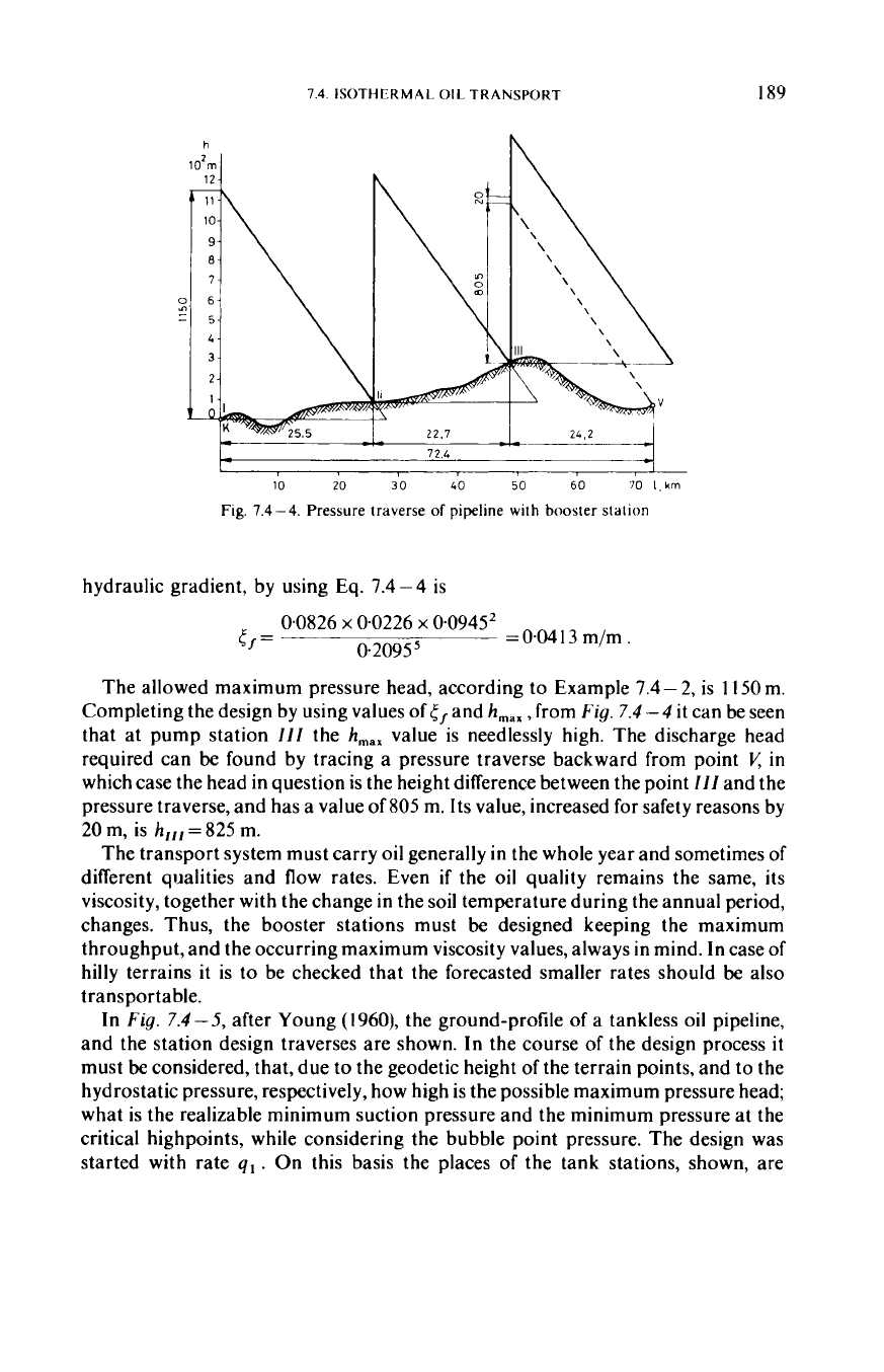
7.4-4).
At
tankless booster stations the suction pressure
may not be lower than the bubble point pressure of the oil. Here, the stations
will
be
closer to each other than
in
ease of transporting systems applying tanks, and,
so
the
number of stations will be greater.
Example
7.4-
4.
The transport capacity of the pipeline, described
in
the previous
Example, must be increased
to
340 m3/h by applying booster stations. The location
of the pump stations with tanks is to be designed.
The Reynolds number for an oil flow rate of 340 m3/h =0.0945 m3/s, according to
Eq. 7.4- 7, is 7.6
x
lo4.
The friction factor, calculated from
Eq.
1
.I
-
7 is 0.0226. The
7.4.
ISOTHERMAL
OIL
TRANSPORT
189
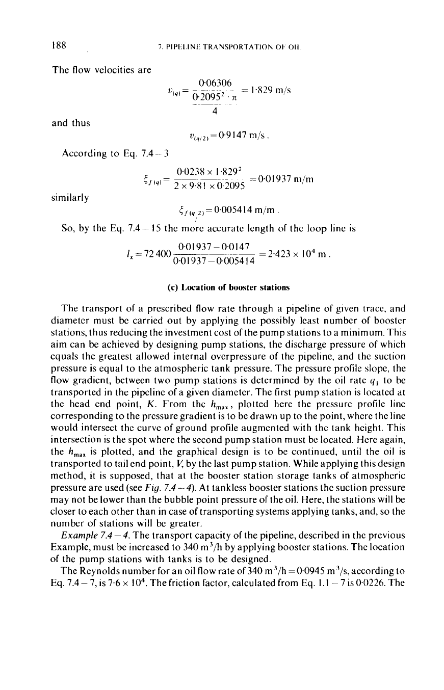
h
10'm
I
10
20
30
40
50
60 70
l,km
Fig.
7.4
-4.
Pressure traverse
of
pipeline with booster station
hydraulic gradient, by using Eq.
7.4-4
is
0.0826
x
0.0226
x
0.09452
0.20955
=OW3
m/m.
r/=
~
The allowed maximum pressure head, according to Example
7.4
-
2,
is
1
150
m.
Completing the design by using values of
(
/
and
h,,,
,
from
Fig.
7.4
-
4
it
can be seen
that at pump station
/I/
the
h,,,
value is needlessly high. The discharge head
required can
be
found by tracing a pressure traverse backward from point
in
which case the head in question is the height difference between the point
//I
and the
pressure traverse, and has a value of
805
m. Its value, increased for safety reasons by
20
m,
is
h,,,
=
825
m.
The transport system must carry oil generally
in
the whole year and sometimes of
different qualities and flow rates. Even
if
the
oil
quality remains the same, its
viscosity, together with the change in the soil temperature during the annual period,
changes. Thus, the booster stations must
be
designed keeping the maximum
throughput, and the occurring maximum viscosity values, always in mind. In case of
hilly terrains
it
is
to
be checked that the forecasted smaller rates should
be
also
transportable.
In
Fig.
7.4-5,
after Young (1960), the ground-profile
of
a tankless oil pipeline,
and the station design traverses are shown. In the course
of
the design process
it
must
be
considered, that, due
to
the geodetic height of the terrain points, and to the
hydrostatic pressure, respectively, how high is the possible maximum pressure head;
what is the realizable minimum suction pressure and the minimum pressure at the
critical highpoints, while considering the bubble point pressure. The design was
started with rate
ql.
On this basis the places of the tank stations, shown, are