Stevenson J. Power system analysis
Подождите немного. Документ загружается.


296
CHAPTER 8 THE IMPEDANCE MODEL AND NETWORK C
A
LCULATIONS
We now see that the new row which must be added to Z
ori
g
In order to nd
� is
Since
Z
bus
must be a square matrix around the principal diagonal, we must add
a new column which is the transpose of the new row. The new column accounts
for the increase of all bus voltages due to
I
", as shown in Eq. (8.17). The matrix
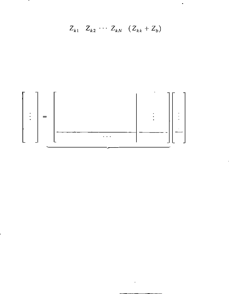
equation is
®
V
I
Z
I
/
1
V
2
LU
/2
-
Z
o
ri
g
.
(
8.
3
2
)
VN
Z
Nk
Iv
I-
I
V
p
®
Z
k
l
Z
k
2
Z
kN
Z
kk
+
Z
b
lp
zhUs(nCw)
Note that the rst N elements of the new row are the elements of row k o
f
Z
ori
g
and the rst N elements of the new column are the elements of column k of
Z
orig'
CASE 3. Adding Zb fr om isting bus ® to the reference node
To see how to alter
Z
Orig
by connecting an impedance
Z
from an existing
bus ® to the reference node, we add a new bus
®
connected through
Z
b to
bus
®. Then, we short-circuit bus ® to the reference nod� by letting
V
p equal
zero to yield the same matrix equation as Eq. (8.32) except that
V
p is zero. So,
for the modication we proceed to create a new row and new column exactly
th
e same as in Case 2, but we then eliminate the (N
+
1) row and (N + 1)
column by Kron reduction, which is possible because of the zero in the column
matr of voltages. We use the method developed in Eq. (7.50) to nd each
element Z"i(IICW)
in the new matrix, where
Z
- Z
_
Z
h(N+
l
)
Z
(N+
l
)
i
- 2008 — 2025 «СтудМед»
