Skiadas C.H., Skiadas C. Chaotic Modelling and Simulation. Analysis of Chaotic Models, Attractors and Forms
Подождите немного. Документ загружается.

234 Chaotic Modelling and Simulation
reach the periphery of the attractor, and then they follow the trajectory that leads to
the attracting point.
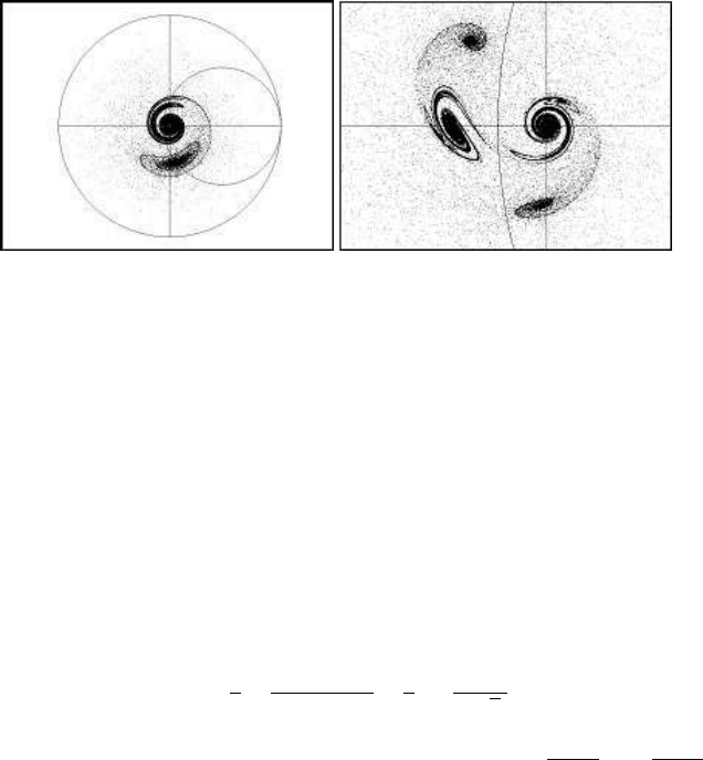
The same behaviour is seen in the next example (Figure 11.8(b)), where the para-
meters are a = 5 and c = 2, while the other parameters remain unchanged. Now two
attractors appear, and each attractor is connected to the attracting point with trajec-
tories. In Figure 11.8(b), the attracting points are the points where x
n+2
= x
n
and
y
n+2
= y
n
, while, in Figure 11.8(a), the attracting point is the point where x
n+1
= x
n
and y
n+1
= y
n
.
(a) Attractor and attracting point (b) Two attractors and the accompanying
attracting points
FIGURE 11.8: Attractors and attracting points in rotation-translation model
11.3.1 A special rotation-translation image
This example comes from Contopoulos and Bozis (1964). The situation exam-
ined was that of two galaxies approaching each other. Here, we apply a rotation-
translation model with space contraction. The rotation angle and the other para-
meters, except for the space contraction parameter, are the same as in Contopoulos
and Bozis (1964). The rotation angle has the form:
θ = −d
1
6
ln
r
2
− cr + c
2
(r + c)
2
−
1
3
tan
2r − c
c
√
3
!
The parameters for the system are a = 4 for translation, and c =
1
0.012
1/3
, d =
0.0055
0.012
2/3
and b = 0.9 for space contraction. The resulting shape is illustrated in Figure 11.9.
A number of particles are introduced into a small circle near the centre of coordi-
nates. The particles follow characteristic trajectories over time. The image is quite
complicated. There are several attracting points, as well as places with high and low
density.

Chaos in Galaxies and Related Simulations 235
FIGURE 11.9: A rotation image following a Contopoulos-Bozis paper
(approaching galaxies)
11.4 Rotation-Reflection
It is interesting to explore the relationships between chaotic attractors in the pres-
ence of rotation and reflection respectively, for the same set of parameters. One
would expect that the attractors for the reflection case would be a mirror image of
the attractors for the rotation case. This can be seen in some particular cases, for in-
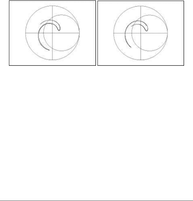
stance in the following, where the rotation or reflection angle is of the form θ
n
= dr
2
.
The parameters in both cases (Figure 11.10(a) illustrates rotation and Figure 11.10(b)
illustrates reflection) are, a = 2, b = 0.5 and d = 0.65. The chaotic forms of the at-
tractors verify the assumption that there is a mirror-image relationship between the
two.
The chaotic geometric modelling approach presented in this section could be use-
ful in galaxy simulations. Chaotic attractors and other forms that appear in real space
(x, y) simulations indicate that elements of any form can be trapped inside these at-
tractors. When the space contraction parameter b < 1 three cases appear, according
to the magnitude of the rotation angle θ:
1. the particles lead to attracting points where they disappear as if in a black-hole,
2. in the presence of a chaotic attractor, the particles will stay or oscillate inside
this attractor, and
3. the particles follow trajectories leading away from the rotating system if the
translation parameter is relatively high.
236 Chaotic Modelling and Simulation
(a) Rotation image (b) Reflection image
FIGURE 11.10: Comparing chaotic forms: rotation-reflection
Various chaotic geometric forms appear. Special characteristics of these forms,
such as the coordinates of the centre and the geometric interactions of these forms
between each other, can, in some cases, be estimated. Some chaotic forms form
groups or clusters in real space. Some chaotic forms are divided into other similar
forms when the parameters of the model take particular values. These chaotic forms
specify places in space that attract masses (particles) from the space around.
This kind of chaotic simulation of galaxy forms has the advantage that it needs
limited computing power, and it mainly models “space,” rather than “elements” in
that space. The explanatory ability of chaotic models is high and could be useful in
many cases.
11.5 Relativity in Rotation-Translation Systems
In rotation-translation systems, a number of particles follow circular paths, while,
at the same time, a translation movement takes place. Numerous chaotic and non-
chaotic forms arise. As we derived earlier, a two-dimensional rotation map is area
preserving if the Jacobian determinant of the map is J = 1. The question we would
like to address in this section is how the shape of the attractors changes when the
speed of the rotating system relative to another system, i.e. the relativistic speed,
influences the system parameters. In other words, how do the equations of special
relativity enter into the rotation-translation equation system? The introduction of the
relativity equations into a rotation-translation map will change the Jacobian of the
system, and can thus produce an area-contracting map. The usual obstacle in appli-
cations is that high relativistic speeds are not possible in real situations. However,
computer simulations show that even low relativistic speeds have a considerable in-
Chaos in Galaxies and Related Simulations 237
fluence on the chaotic forms.
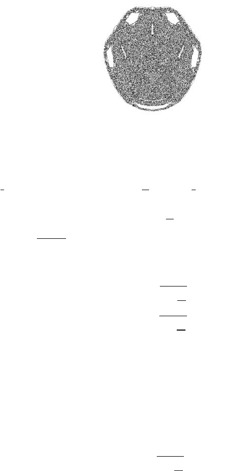
A simple example is presented in the following figures. Figure 11.11 illustrates the
chaotic image from the rotation-translation map without entering relativistic equa-
tions. A chaotic bulge appears.
FIGURE 11.11: A rotation-translation chaotic image
The rotation-translation chaotic bulge presented in Figure 11.11 is formed when
the space parameter is b = 1. The bulge is symmetric. The translation parameter is
a =
π
6
: The other parameters are: c =
π
12
and d =
π
3
. The equation for the rotation
angle is:
θ
n
= c +
d
r
n
where r
n
=
p
x
2
n
+ y
2
n
.
The relativistic-like approach to the rotation-translation equations takes into ac-
count the length contraction governed by the equations:
x
rel
= x
r
1 −
v
2
c
2
y
rel
= y
r
1 −
v
2
c
2
where v is the relativistic speed and c is the speed of light.
Inserting these relativistic forms into the rotation-translation equations
x
n+1
= a + b(x
n
cos 2θ
n
− y
n
sin 2θ
n
)
y
n+1
= b(y
n
sin 2θ
n
+ y
n
cos 2θ
n
)
(11.6)
a new form is obtained. After rearrangement, the relativistic-like coefficient appears
as a change in the parameter b, which now becomes:
b
∗
= b
r
1 −
v
2
c
2
238 Chaotic Modelling and Simulation
When v = 0, the parameter b is set equal to 1. When v = c, then b = 0. In reality,
v ≪ c and the values of b are close to 1. However, even for small relativistic speeds,
the influence on the chaotic bulge and on the space around the bulge is quite evident.
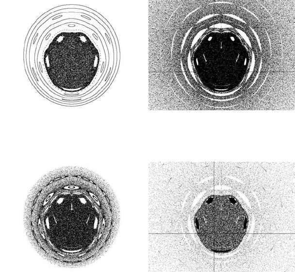
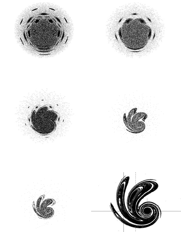
Figure 11.12(a) illustrates the chaotic bulge and the space outside the central chaotic
space. We launch particles at x = (−1.5, −1.4, . . . , 0) and y = 0.1. The space outside
the chaotic bulge is characterised by closed curves and islands.
A relativistic speed equal to 1000km/sec corresponds to b = 0.9999945 for the
space contraction parameter b. The influence of this change of parameter b in the
shape of the previous object is illustrated in Figure 11.12(b). First of all, we observe
that the non-chaotic lines outside the chaotic bulge disappear. On the other hand,
the lines expand, covering more space and joining each other. Over time, the space
outside the chaotic image is covered by particles that are directed towards the chaotic
bulge. The non-chaotic islands are shorter. This is more clear in Figure 11.12(c), in
which the relativistic speed is v = 2500km/sec, corresponding to a shape contraction
parameter b = 0.999965. When v = 2760km/sec, a chaotic limit is present. The
islands in the chaotic sea are transformed into attracting regions, as illustrated in
Figure 11.12(d). The particles from the chaotic bulge are directed into these regions,
and the equilibrium points in these regions become attracting sinks.
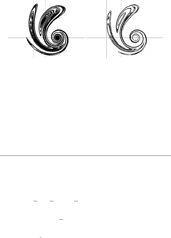
When the relativistic speed v is between 2760km/sec and 89000km/sec, the par-
ticles are guided to the points of attraction. However, a change in the images takes
place as the relativistic speed gets higher. This is shown in Figures 11.13(a) through
11.13(f). After the limiting speed v ≈ 2760km/sec, symmetry breaks down. This
is very clear when v = 10000km/sec and b = 0.99944 (Figure 11.13(b)). In Fig-
ures 11.13(c) through 11.13(e), the relativistic speed takes higher values (those val-
ues being v = 20000km/sec and b = 0.99778, 50000km/sec and b = 0.9860, and
70, 000km/sec and b = 0.9724 respectively), and the images take a rotation form
with three main arms and a smaller one. When v = 89, 000km/sec and b = 0.954981,
the rotating image has the form of a chaotic attractor where there are no attracting
points or sinks, and the particles are trapped in the space covered by the chaotic
attractor. The attractor is a totally non-symmetric rotation object with two main
rotation arms and a smaller one (Figure 11.13(f)). A circular disk is centred at
(x, y) = (a, 0).
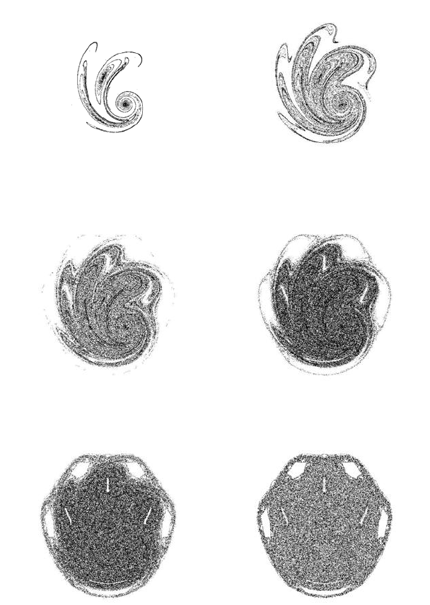
The chaotic attractor becomes sharper for high relativistic speeds, namely values
higher than v = 89, 000km/sec, as illustrated in the following two figures. In Fig-
ure 11.14(a) the chaotic image is simulated for v = 120, 000km/sec and b = 0.9165,
whereas in Figure 11.14(b) the relativistic speed is in the upper limit for attractor
formation, at v ≈ 170000km/sec (b = 0.8239471).
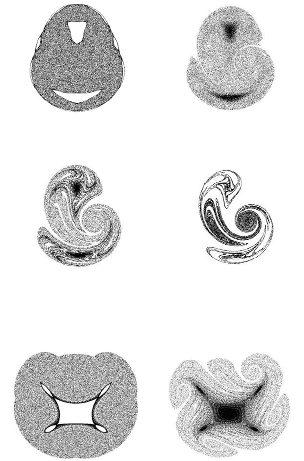
A very surprising property of the rotation-translation system is that the chaotic
image produced under the relativistic influence in large relativistic speeds is present
at the beginning of the process, when time t is very small, if the area contracting
parameter b = 1. In Figures 11.15(a) through 11.15(f), illustrations of the chaotic
evolution during the first time periods appear.
The particles introduced at time t = 0 are distributed in a small circle centred at the
origin. The radius of this circle is r
intr
= 0.01. At the beginning of the process, at time
t = 10, the image is similar to that appearing in Figure 11.14(b), where the relativistic
Chaos in Galaxies and Related Simulations 239
(a) Non-relativistic rotation-translation
for v = 0 (b = 1)
(b) Relativistic-like rotation-translation
for v = 1000 (b = 0.9999945)
(c) Chaotic forms for speed v =
2500km/sec
(d) Chaotic limit at speed
v = 2760km/sec
FIGURE 11.12: Chaotic forms for low relativistic speeds
240 Chaotic Modelling and Simulation
(a) v = 5000km/sec (b) v = 10000km/sec
(c) v = 20000km/sec (d) v = 50000km/sec
(e) v = 70000km/sec (f) v = 89000km/sec
FIGURE 11.13: Relativistic rotation-translation forms for medium and high
relativistic speeds
Chaos in Galaxies and Related Simulations 241
(a) v = 120000km/sec (b) v = 170000k m/sec
FIGURE 11.14: Relativistic rotation-translation forms for high relativistic
speeds
speed is v = 170000k m/sec and the space contracting parameter is b = 0.8239471.
Instead a similar image is now produced at time t = 10, but with parameter b = 1.
The image is totally non-symmetric. As the time t increases, the chaotic images
become more symmetric, and at time t = 500 the resulting Figure 11.15(e) is a
symmetric object almost identical to the equilibrium stage image (Figure 11.15(f))
resulting when t → ∞.
11.6 Other Relativistic Forms
More rotation-translation relativistic objects are based on the above equation forms
but with different values for the parameters: a = 0.8π, c = 0.4π and d = 1.6π. The
resulting relativistic forms are illustrated in Figures 11.16(a) through 11.16(d).
A rotation-translation relativistic model based on the above equation forms, with
parameters a =
4π
3
, c =
4π
3
and d =
4π
3
, provides the relativistic images presented in
Figures 11.17(a) and 11.17(b).
A rotation-translation relativistic object based on the above equation forms, with
parameters a = c = d =
2π
0.3
, results in the relativistic forms illustrated in Fig-
ures 11.18(a) through 11.18(c).
Figure 11.18(c) illustrates a pair of galaxy-like objects formed for very high rel-
ativistic speed v =
c
3
= 100000km/sec. However, similar objects appear in the first
time periods of the same rotation-translation procedure, but for b = 1, as illustrated
in Figures 11.18(d) through 11.18(h). In this case, the original circular disk of par-
ticles has radius r = 5. Very early, at times t = 4 and t = 6, a pair of two-armed
spiral galaxies appears. Later on, at time t = 10, a circular arm appears, and at time
t = 20, the two spiral galaxies are connected through two connecting circular arms.
242 Chaotic Modelling and Simulation
(a) t = 10 (b) t = 20
(c) t = 50 (d) t = 100
(e) t = 500 (f) t → ∞
FIGURE 11.15: Non-relativistic chaotic images in the early period of a
rotation-translation process with b = 1
Chaos in Galaxies and Related Simulations 243
(a) v = 0 (b) v = 20.000km/sec
(c) v = 50.000km/sec (d) v = 100.000k m/sec
FIGURE 11.16: Other relativistic chaotic images
(a) Chaotic form for speed v = 0 (b) Chaotic form at speed
v = 30000km/sec
FIGURE 11.17: Various relativistic chaotic forms
