Short T.A. Electric Power Distribution Handbook
Подождите немного. Документ загружается.


Distributed Generation 709
the timing and duration of pulses, the controller can shape the current
supplied to the system. A common three-phase configuration is a three-phase
bridge (the same as Figure 14.3, but with IGBTs instead of thyristors). In a
grid-connected application, a PWM inverter can control the power factor; in
stand-alone, the inverter can operate alone and control voltage. PWM invert-
ers normally have switching frequencies from 1 to 10 kHz. They produce
little low-order harmonics, and the high-frequency harmonics near the
switching frequency can be filtered with relatively small filters. Generally,
PWM designs have distortion well within IEEE Std. 519-1992.
Self-commutated inverters may be voltage controlled or current controlled.
The voltage-controlled inverter is simpler; the controller creates a reference
voltage. The current-controlled mode is more suitable for distributed gener-
ators; the controller uses the utility voltage as a reference and injects current
at the proper angle (usually at unity power factor). Current-controlled invert-
ers produce little fault current. Overcurrent protection removes current
almost immediately after an overcurrent (manufacturers implement this to
protect their equipment; IGBTs have very limited overcurrent capability).
The current pulse before the controller stops firing is typically less than 2
per unit peak and lasts about 200 to 300 msec.
Self-commutated inverters are used on most smaller inverter-based gen-
erators. Very large units still require line-commutated inverters. With con-
tinued advances in power electronic switching technologies, larger units will
migrate to self-commutated designs.
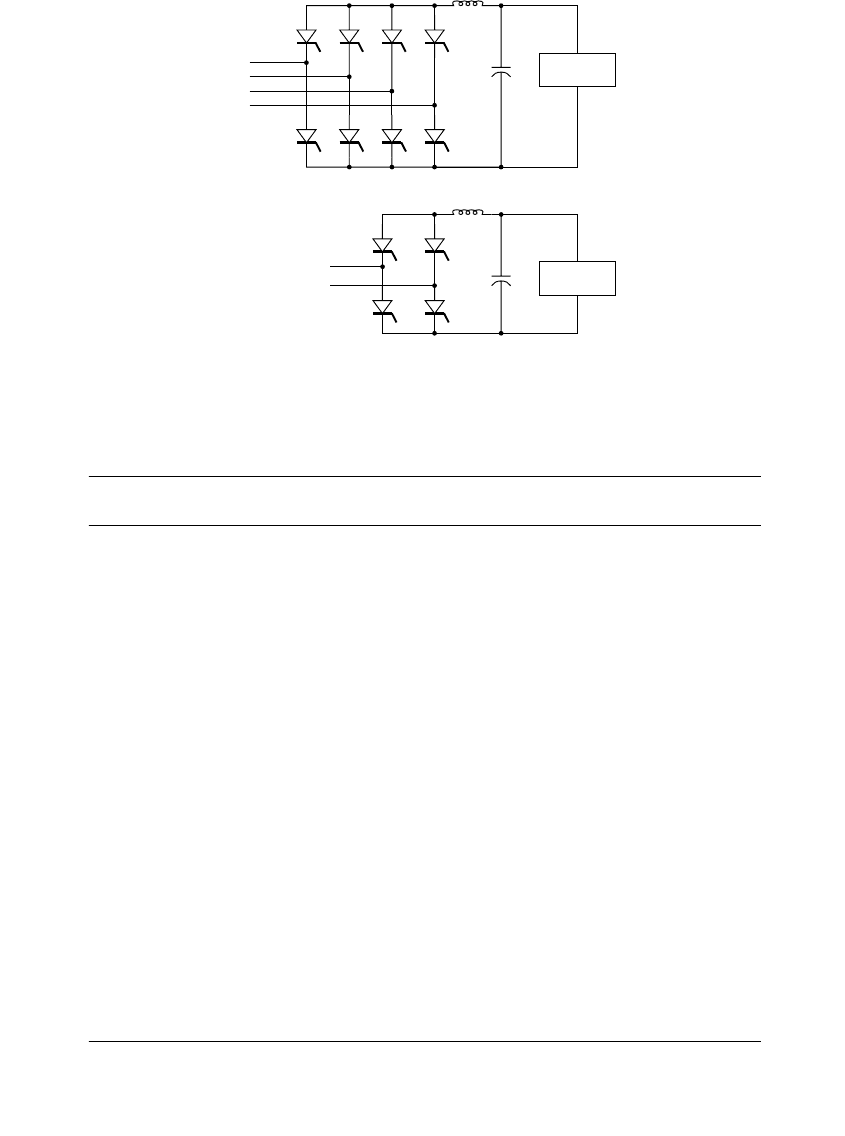
Many three-phase inverter configurations are ungrounded, like the design
in Figure 14.3, which raises interfacing issues on grounded distribution
circuits. Often, ungrounded inverter configurations are interfaced with
grounded systems through a grounded-wye – delta transformer. This is a
grounding transformer; circulating currents in the delta allow the trans-
former to supply unbalanced load. Some inverter configurations are
grounded, such as those in Figure 14.4. Thyristors are shown, but PWM
inverters with the same configurations are common. Three single-phase
inverters can also supply grounded three-phase systems.
Whether an inverter or a rotating generator, all energy converter technol-
ogies have interconnection issues, just different ones. Table 14.2 summarizes
some of the most important issues for each major power converter type.
14.1.5 Modeling Small Generators
The simplest load-flow model of distributed generators is as a negative load.
The normal load models include constant power, constant impedance, and
constant current. More accurate representations depend on the type of gen-
erator and its controls.
Since most synchronous DGs operate in a voltage-following mode with a
set injection of real and reactive power, the most accurate model is the
constant power model. In some programs, the power on each phase must
1791_book.fm Page 709 Monday, August 4, 2003 3:20 PM
(C) 2004 by CRC Press LLC
710 Electric Power Distribution Handbook
FIGURE 14.4
Grounded inverter configurations.
TABLE 14.2
Power Converter Characteristics from an Interconnection Perspective
Feature
Synchronous
Generator
Induction
Generator Inverter
Ability to operate as
an isolated (stand-
alone) source
Exciter allows it to
operate as a stand-
alone island
Not intended for
stand-alone island
but still can
accidentally self-
excite if isolated with
a capacitor
Self-commutated
voltage source
inverters can
function as islands
Synchronism with
Utility
Must operate as a
synchronous source
Typically operated
with several percent
slip
Must operate as a
synchronous source
Fault contributions 4–8 times rated
current for a few
cycles
4–8 times rated
current for a few
cycles
Usually less than 2
times rated current
and very short
duration
Var injection and
control capability
Yes — by adjusting
exciter can regulate
vars and inject either
leading or lagging
power into system
No var control — is a
lagging source
(capacitors needed to
correct vars)
Some inverters can
vary var output and
provide reactive
support, most
operate near unity
power factor
Response speed to
load changes and var
needs
Exciter and throttle
require some time to
respond
Induction generator
does not have exciter
control. Throttle
response requires
time
Inverter can respond
almost instantly to
detected conditions
to control power and
vars if suitably
designed with energy
storage on bus
Active anti-island No No Yes
Source: EPRI PEAC, “Distributed Generation Course,” 2002.
dc source
A
B
C
N
Grounded three-phase inverter
Grounded single-phase inverter
dc source
A
N
ac output
1791_book.fm Page 710 Monday, August 4, 2003 3:20 PM
(C) 2004 by CRC Press LLC

Distributed Generation 711
be specified. A somewhat more accurate model is to keep the total power
constant while the balance of the three phases is determined by the sequence
parameters of the generator (Chen et al., 1991). For induction generators, the
reactive power changes with voltage, but the changes are small enough that
they can be modeled as constant power devices. See Barker and Johnson
(2002) for more on modeling rotating machines for different scenarios.
If a synchronous generator is operated in a voltage-regulating mode, the
best load-flow model is as a voltage-regulating, constant real power device.
The reactive power limits would also need to be specified.
A constant-power model accurately describes forced-commutated invert-
ers (for microturbines, fuel cells, photovoltaics, etc.), such as those using
pulse-width modulation. The inverters have control loops that control both
real and reactive power. Line-commutated inverters can also be modeled as
a constant power. They are limited in that they can only absorb reactive
power and cannot supply vars to the system.
Fault contributions of rotating generators can be modeled with most dis-
tribution short-circuit programs using the appropriate subtransient and tran-
sient characteristics of the generator. Short-circuit analysis can be done using
a standard short-circuit program. Although the addition of distributed
resources increases the time-varying nature of the fault current, it is not
enough to warrant using a stability or EMTP-type model for fault analysis.
Industrial systems with large local generators are still analyzed properly
with standard short-circuit analysis programs.
When considering the effects on protection coordination with distributed
generators, we can use standard protection programs. With fault contribu-
tions from only one source, curves of two overcurrent devices can be plotted
on a time–current curve that will demonstrate visually the coordination over
a range of currents. With contributions from different sources, it is more
difficult to plot curves in a time–current graph. It is more useful to do a table
of operating times of different devices for faults at different locations.
More complicated transient modeling is sometimes warranted for large
machines or large penetration levels on distribution lines (especially on weak
circuits). Transient simulations provide better answers on possible problems
related to ferroresonance, voltage flicker, stability, and islanding (EPRI TR-
111490, 1998; EPRI TR-112737, 1999).
14.2 Islanding Issues
Islanding is a major interconnection issue. Islanding is a situation where one
or more generators and a portion of the utility system operate separately
from the rest of the utility system. The formation of an unintentional island
is a problem for the utility company. The most important concerns are
1791_book.fm Page 711 Monday, August 4, 2003 3:20 PM
(C) 2004 by CRC Press LLC

712 Electric Power Distribution Handbook
•Worker and public safety
• Damage to utility and customer equipment due to out-of-phase
reclosure
•Voltage problems
• High overvoltages to utility equipment and customers caused by
neutral shifts or ferroresonance
Distributed generators create danger for workers and the public. Line
crews might work on a section of line that they thought was de-energized.
A distributed generator could energize this line, even though it is discon-
nected from the utility source. The danger also extends to the general public.
Islanded generators may energize downed conductors within public reach
(that might have been de-energized by upstream utility switchgear had the
island not developed).
Once an island forms, it typically drifts out of phase with the utility system
voltage. If the main system is closed into the island, the out-of-phase reclo-
sure may cause damage to the generator, customer loads, and/or utility
switchgear as well as being a significant power quality disturbance for cus-
tomers upstream of the island. An island may also prevent the clearing of
fault currents on the system, increasing damage at the location of the fault,
and perhaps burning conductors down.
The most common means to prevent islanding is to use voltage and fre-
quency relays on the generator to trip whenever either of these two param-
eters migrate outside a selected window. This form of islanding protection
is known as passive protection. It prevents islanding in most cases because
when a section of the distribution system and one or more generators sep-
arate together, the output of the generator will not match the load on the
island. For synchronous or induction generators, the voltage and frequency
will drift, which will trip the relays in a short time. Typically the relays are
set to a tight frequency range of perhaps +1 Hz or even +0.5 Hz. Voltage
relays have a bit wider window to allow for typical voltage regulation
excursions on the circuit (+5 to 10% is typical). Later in this chapter, specific
setting requirements per IEEE standards are discussed.
Synchronous generators, induction generators, self-commutated inverters,
and line-commutated inverters — all can island. Synchronous generators
and self-commutated inverters are most likely to island because they do not
require external excitation. Induction generators and line-commutated
inverters can island if they have external excitation, either from capacitor
banks or from other generators in the island.
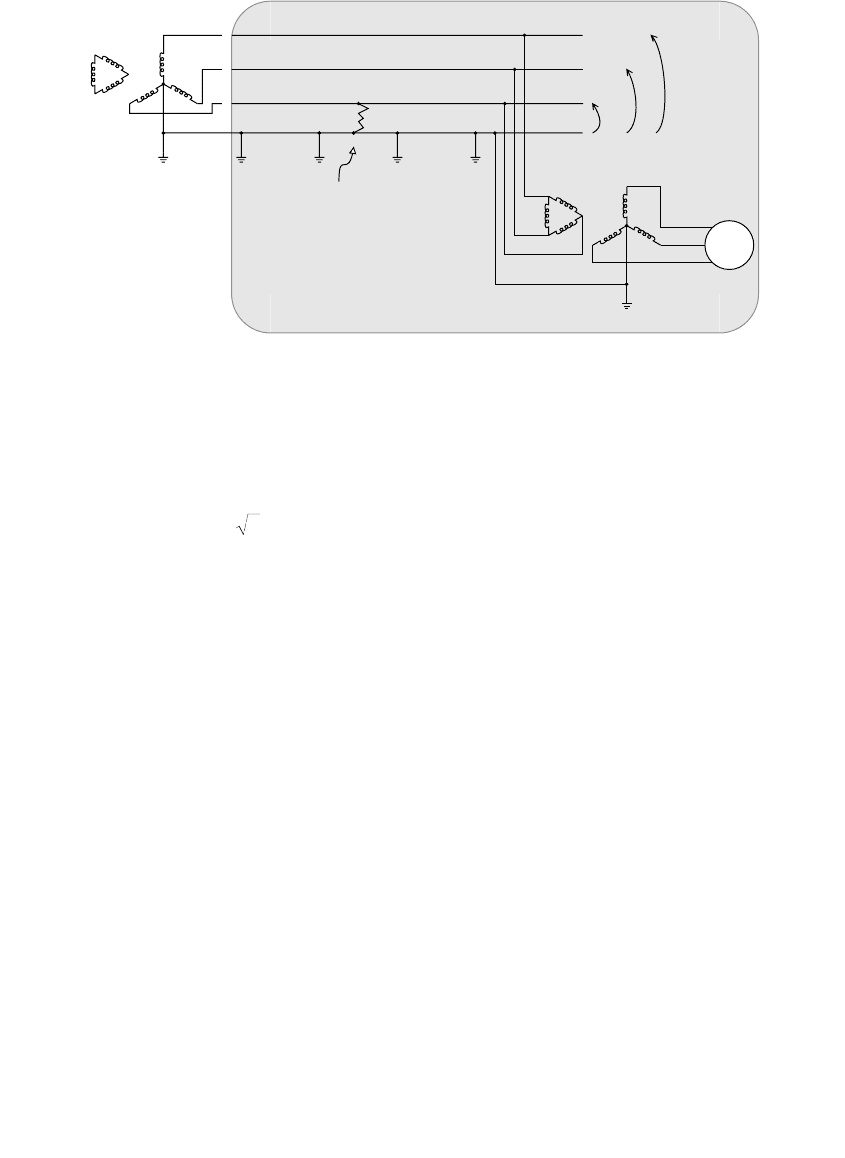
14.2.1 Effect of Transformer Connections on Overvoltages
Generators fed from a transformer with an ungrounded high-side connection
can drive a normally grounded utility circuit as an ungrounded island. When
a single line-to-ground fault occurs on the distribution system and the sub-
1791_book.fm Page 712 Monday, August 4, 2003 3:20 PM
(C) 2004 by CRC Press LLC
Distributed Generation 713
station breaker (or a recloser) opens, the system becomes a three-wire,
ungrounded system driven by the ungrounded generator. The fault moves
the potential of the ground to the phase potential (see Figure 14.5). That
leaves the line-to-neutral voltage on the unfaulted phases equal to the line-
to-line voltage ( = 1.73 times the normal line-to-neutral voltage).
The interconnection transformer configuration and the generator ground-
ing determine if the application is effectively grounded. The most common
transformer configurations (the connection notation indicates the primary-
side connection, then the secondary-side [generator-side] connection) are
• Delta – grounded wye — Leaves the circuit ungrounded.
• Grounded wye – grounded wye — Can effectively ground the source
if the generator is effectively grounded. Is ungrounded if the gener-
ator is ungrounded.
• Grounded wye – delta — Provides the best way to effectively ground
a generator interconnection, but creates a ground source.
• Grounded wye – delta with a grounding reactor on the high-side wye —
Limits the ground fault source while still maintaining grounding.
Transformer/generator grounding involves a tradeoff. The best grounding
arrangements create sources for ground current that may interfere with
distribution protection. Limiting ground current creates an interconnection
that is not grounded as well (higher overvoltages).
Grounded-wye – grounded-wye transformers are widely used and famil-
iar to utilities. They are often the best connection if the generator is grounded.
If the generator neutral connection is not grounded or does not meet effective
grounding requirements, then the transformer bank does not effectively
FIGURE 14.5
An ungrounded generator connection driving an island with a line-to-ground fault.
Open utility
breaker
DG
Line-to-ground
fault
Island
V = 0
V = 173%
V = 173%
Ungrounded DG source
3
1791_book.fm Page 713 Monday, August 4, 2003 3:20 PM
(C) 2004 by CRC Press LLC

714 Electric Power Distribution Handbook
ground the source even though the neutral connections to the transformer
are grounded on both sides. Some rotating machines are not designed to
withstand the forces due to a line-to-ground fault on the generator terminals.
For this reason, they are grounded through an impedance or ungrounded
(so they are not effectively grounded). Some inverters need isolation from
ground and are not designed to operate with a grounded-wye winding on
the inverter side of the transformer. For grounded rotating machines, the
grounded-wye – grounded-wye connection also supplies significant zero-
sequence current (it is a grounding source).
Generator installers often prefer the grounded-wye – delta transformer
(with the delta on the generator side). This connection grounds the connection
regardless of the generator grounding (the generator may be ungrounded or
grounded through an impedance to protect it from line-to-ground faults).
Other advantages are reduced harmonics, isolation between the primary and
secondary for ground faults, and a smaller voltage sag seen on the generator
terminals. The main drawback to using the grounded-wye – delta connection
is that it is a grounding bank; it feeds ground faults on the primary. This can
interfere with distribution system coordination and desensitize ground relays,
improperly blow fuses, or falsely operate sectionalizers, reclosers, or breakers.
Large circulating currents in the delta winding on the secondary (usually due
to ground faults) can also damage the interconnection transformer. Adding
a reactor to the neutral connection of the primary-side wye reduces the
grounding transformer effect while still maintaining acceptable grounding.
If generators interface through ungrounded transformer connections, the
preferred way to control overvoltages is with a ground overvoltage relay (a
59G, discussed in the next section).
Some large generators are applied right at distribution primary voltage,
without an interfacing transformer. This has the same effects as using a
grounded-wye – grounded-wye transformer. If the generator is ungrounded,
islanded overvoltages are possible. Solidly grounding the generator grounds
the source.
Arcing ground faults are another possible overvoltage mode on islands
supported by ungrounded generators. On ungrounded systems, intermittent
arcing grounds can create switching surge overvoltages from the restriking
of the arc (see Chapter 13). A system that is designed to be ungrounded has
only line capacitance between the phases and ground. An ungrounded island
has the line capacitance and line-to-ground load. The load may help control
arcing ground faults. If the island has grounded-wye capacitor banks, arcing
ground fault overvoltages may be more likely. This is an area that needs
more study.
14.2.1.1 Overvoltage Relays and 59G Ground Fault Detection
Distributed generators usually have over- and undervoltage relays. A typ-
ical overvoltage relay uses a type 59T time-delay relay with a pickup of 5
1791_book.fm Page 714 Monday, August 4, 2003 3:20 PM
(C) 2004 by CRC Press LLC
Distributed Generation 715
to 10% above nominal voltage. The time setting should be set above the
normal clearing time of the feeder relays but less than the substation
breaker reclosing time. A reasonable setting is 30 to 60 cycles (ANSI/IEEE
Std. 1001-1988). It is best if an instantaneous element (59I) is also used,
although a higher setting (such as 40% above nominal) may be needed to
prevent excessive nuisance trips. For overvoltages, primary-side measure-
ments are best, especially if the primary winding is ungrounded. Secondary
measurements cannot detect the neutral shift on an ungrounded island
with a ground fault. To detect and trip on overvoltages, every phase must
have a relay, not just on an individual phase and not on an average of the
three phases. Undervoltage relays also provide backup for neutral-shift
overvoltages by detecting the voltage sag on the phase with the line-to-
ground fault.
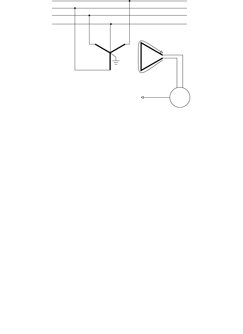
The 59G relay detects neutral-shift overvoltages with the connection
shown in Figure 14.6. The grounded-wye – broken-delta potential trans-
former arrangement sums the three phase-to-neutral voltages.
The main drawback of relaying schemes is that the overvoltage still occurs;
even a short-duration overvoltage may damage some equipment. The over-
voltage duration is limited by the speed of the relays and breaker. Depending
on the speed of the relaying, these limits may not coordinate with the tem-
porary overvoltage capability of some arresters or sensitive customer equip-
ment. Also, if the relaying fails to operate, the overvoltage could last for
some time. Another disadvantage of this approach is that primary-side
potential transformers are required. Because of this, many utilities avoid
ungrounded transformer connections.
FIGURE 14.6
Ground fault overvoltage detection scheme (59G).
Primary-side PT bank
Grounded wye -- Broken delta
Zero sequence
components in phase
59G
Generator trip signal
A
B
C
N
1791_book.fm Page 715 Monday, August 4, 2003 3:20 PM
(C) 2004 by CRC Press LLC

716 Electric Power Distribution Handbook
14.2.1.2 Effectively Grounding a Grounded-Wye – Grounded-Wye
Transformer Connection
Effectively grounded systems limit the overvoltage caused by a neutral shift
to 25% above nominal. In effectively grounded systems the ground fault
current is 60% or more of the available three-phase fault current. A grounded-
wye – grounded-wye transformer is effectively grounded if the generator
applied to it meets effective grounding requirements. The conditions for
effective grounding are approximately (ANSI/IEEE C62.92-1987):
X
0
/X
1
£ 3 and R
0
/X
1
£ 1
For effective grounding during islanding for a ground fault on the primary
terminals, the generator must be solidly grounded or the impedance must
be small enough to meet the criteria above. For a rotating generator with a
grounding reactor, the criteria (EPRI 1000419, 2000) is
X
GN
£ X
T1
+ X
G1
- X
T0
/3 -
X
G0
/3
where
X
GN
= generator neutral reactance
X
T0
= transformer zero-sequence reactance
X
T1
= transformer positive-sequence reactance
X
G0
= generator zero-sequence reactance
X
G1
= generator positive-sequence reactance
14.2.1.3 Sizing a Neutral Grounding Reactor on a Grounded-Wye –
Delta Connection to Maintain Effective Grounding
A grounding reactor added to a grounded-wye – delta transformer limits the
zero-sequence fault contribution and limits the circulating current in the delta
winding. In order to ensure that the connection still maintains an effectively
grounded system during a possible island, the grounding reactor cannot be
too large. The criteria for effective grounding is: X
0
/X
1
£ 3. This depends on
the characteristics of the generator and interconnection transformer. For a
primary ground fault at the transformer, the sequence impedances are
X
0
= X
T0
+ 3X
N
X
1
= X
T1
+ X
G1
where
X
N
= neutral reactance
X
T0
= transformer zero-sequence reactance
X
T1
= transformer positive-sequence reactance
X
G1
= generator positive-sequence reactance
1791_book.fm Page 716 Monday, August 4, 2003 3:20 PM
(C) 2004 by CRC Press LLC

Distributed Generation 717
To keep the interconnection effectively grounded, limit the size of the
reactor according to (EPRI 1000419, 2000):
X
N
£ X
T1
+ X
G1
- X
T0
/3
Note that this only guarantees effective grounding for a fault right at the
grounding transformer. For faults at other points on the feeder, add the zero
and positive-sequence line impedances between the fault location and the
generator to X
T0
and X
T1
If line impedances are considered, then the zero-
sequence line resistance should also be considered. In the equations above,
the resistance portion has been ignored because the X/R ratios on generators
and transformers are high. Another requirement for effective grounding is
that R £ 1. Normally, these are small, so we can ignore them except for a
very large generator on a weak system.
14.2.2 Anti-Islanding Protection
At most sites, voltage and frequency relays are the main protection against
islanding. When a utility protective device opens and leaves an island, nor-
mally, the generation and load will not match. If the generation exceeds the
load, the voltage rises and the generators speed up. The opposite occurs if the
load exceeds the generation. In either case, when voltage or frequency goes
outside of normal limits, voltage or frequency relays should trip the generators.
Over- and undervoltage relays are an important line of defense against
islanding. Typically, this consists of
• Overvoltage time-delay relay (59T) — A pickup of 5 to 10% above
nominal voltage is generally used. The time setting should be set
above the normal clearing time of the feeder relays but less than the
substation breaker reclosing time. A reasonable setting is 1/2 to 1 sec.
• Instantaneous overvoltage element (59I) — An instantaneous overvolt-
age element is recommended (but not always used). A higher setting
(such as 40% above nominal) may be needed to prevent excessive
nuisance trips.
• Undervoltage time-delay relay (27T) — A pickup of 5 to 10% below
nominal voltage is generally used. Similar time settings should be
used as the overvoltage time-delay relay.
• Instantaneous undervoltage relay (27I) — As with the overvoltage
instantaneous element, a loose setting is necessary to prevent nui-
sance trips (30% below nominal is reasonable).
The time-delay relays are time delays; they are not inverse-time relays. If
the voltage on a 59T relay is above the magnitude setting for longer than
the time setting, it trips. If the voltage drops back below the magnitude
1791_book.fm Page 717 Monday, August 4, 2003 3:20 PM
(C) 2004 by CRC Press LLC

718 Electric Power Distribution Handbook
setting, the timer resets after the given reset time. Many generator-protection
relays allow multiple pairs of magnitude and time-delay settings to achieve
a stair-step voltage-time characteristic.
For overvoltages, it is best if the detecting potential transformers are on
the primary side of the generator transformer (especially if the primary
winding is ungrounded). For example, the neutral shift on an ungrounded
island with a ground fault will not be detected on the secondary side of the
transformer. To detect and trip on overvoltages, individual relays should be
on each of the three phases (not just on an individual phase and not on an
average of the three phases). The undervoltage relays will also provide
backup for neutral-shift overvoltages by detecting the voltage sag on the
phase with the line-to-ground fault.
The over- and underfrequency relay (81U/O) is another line of defense
against islanding. Trip thresholds of ±1% are common. Wide ranges of time
delays are used for a 1% setting: 0.1 sec to many seconds. Some utilities
specify a wider range for the underfrequency setting to allow the generator
to stay in for low-frequency events caused by system-wide disturbances. The
low frequency indicates a need for generation, so it helps to have the dis-
tributed generation remain connected.
Integrated generator relay packages are available from several manufac-
turers. These provide voltage and frequency relays along with other inter-
connection functions such as synchronization (and possibly all of the
generator protection functions as well).
EEI (2000) provides guidance for applying anti-islanding relaying and
other interconnection equipment for several different types of generators
and interconnection transformers.
With voltage and frequency relays, there is still some chance that evenly
balanced generation and load can drive islands. Because voltage and fre-
quency relays are not 100% reliable, some large distribution generators have
transfer-trip protection schemes. Breakers (or reclosers) upstream of the gen-
erator send a trip signal to the generator — if the breaker operates, it trips
the generator. This requires a reliable communication line between the
breaker and the generator.
14.2.3 Active Anti-Islanding
Inverter-based generators can use more sophisticated ways to detect islands.
If the generation and load are almost equal, an island may take some time
to drift in voltage and frequency. Active anti-islanding inverters attempt to
push the voltage and/or frequency out of normal limits. Under normal
conditions, the inverter cannot budge the voltage or frequency; with the
inverter connected to the utility system, the utility system fixes the voltage
and current (assuming the utility system is much bigger than the generation).
The most promising active anti-islanding techniques are the Sandia volt-
age-shift and frequency-shift methods (Stevens et al., 1999). These use pos-
1791_book.fm Page 718 Monday, August 4, 2003 3:20 PM
(C) 2004 by CRC Press LLC