Short T.A. Electric Power Distribution Handbook
Подождите немного. Документ загружается.


Grounding and Safety 669
Ground rods are the most common grounding electrode. The NESC
requires at least an 8-ft (2.45-m) rod; iron or steel rods must be at least 5/8
in. (15 mm) in diameter; copper-clad stainless steel, or stainless steel-clad
rods must be at least 1/2-in. (12 mm). Rods should be driven to at least 8 ft
(2.45 m). If a driven rod hits a rock bottom, the depth may be less than 8 ft
(2.45 m). Strategies are to drive the rod at an angle or to use another type
of ground such as a buried strip. NESC requires buried strips to be at least
10 ft (3 m) and have a total surface area of at least 5 ft
2
(0.47 m
2
). Guy anchors
are not allowed as grounding electrodes.
The resistivity of a ground rod is
where
r = soil resistivity, W-m
L = length of the ground rod, m
a = radius of the ground rod, m
As a good approximation for 10-ft (3.3-m) ground rods, the resistance in
ohms equals the ground resistivity in W-m divided by three. Divide earth
resistivity by 2.5 for an 8-ft rod.
Rod diameter has little impact on the electrode resistance; the diameter is
needed mainly for mechanical strength and to ensure the rod has enough
material to survive corrosion.
Twenty percent of the resistance of a ground rod occurs within 1.2 in.
(3 cm) of the rod, and half of the resistance is in the first 6 in. (15 cm) (IEEE
Std. 142-1991). These numbers vary with the ground resistivity.
The number of rods and the length are the main factors that influence the
resistance. Rods can be driven deeper. Normally, crews drive a section and
then thread on another rod section to pound it in deeper. Deeper rods are
best when lower levels of the soil have lower resistivity, normally because
of more moisture.
Multiple ground rods in parallel effectively reduce the overall resistance.
But, if two ground rods are too close together; they act as one ground rod
with a larger diameter, reducing much of the gain of using parallel rods.
One common rule: separate the rods by a distance of at least the length of
one of the ground rods. The NESC requires ground rods to be at least 6 ft
(1.8 m) apart. Even with these separations, the resistance of n ground rods
in parallel is more than 1/n times the resistance of a single rod. Table 13.2
shows multiplying factors and final resistances for rods placed symmetri-
cally one rod length apart.
The NESC allows other grounding electrodes. Water piping systems make
fantastic grounds if they are available; grounds less than 1 W are common.
Unfortunately, conducting water pipes are not typically installed anymore,
R
L
L
a
=-
Ê
Ë
Á
ˆ
¯
˜
r
p2
4
1ln
1791_book.fm Page 669 Monday, August 4, 2003 3:20 PM
(C) 2004 by CRC Press LLC

670 Electric Power Distribution Handbook
so water system grounds are less common. Gas piping systems are not
allowed as grounding electrodes.
The NESC allows the concentric neutral of a cable to be a ground for direct-
buried cables of at least 100 ft (30 m). The cable neutral must be bare or have
a semi-conducting jacket with a radial resistivity not exceeding 10 W-m
(meaning that 30 m of cable has a resistance of 0.33 W across the jacket).
The NESC allows other “made” electrodes other than ground rods includ-
ing buried wires, strips, and plates. These are especially appropriate in areas
with a rock bottom. Buried wires must have at least a 0.162 in. (4 mm)
diameter, be at least 100 ft (30 m) long, and be at least 18 in. (0.45 m) deep
(less is allowed if a rock bottom is hit). Strips must be at least 10 ft (3 m)
long, buried at least 18 in. (0.45 m) deep, and have a total surface area on
both sides of 5 ft
2
(0.47 m
2
). Plates must be buried at least 5 ft (1.5 m) deep
and have a total surface area of at least 2 ft
2
(0.185 m
2
). Both plates and strips
must have a thickness of at least 0.06 in. (1.5 mm) wide for nonferrous metals
and at least 0.25 in. (6 mm) wide for ferrous metals. Table 13.3 shows resis-
tance calculations for several different configurations.
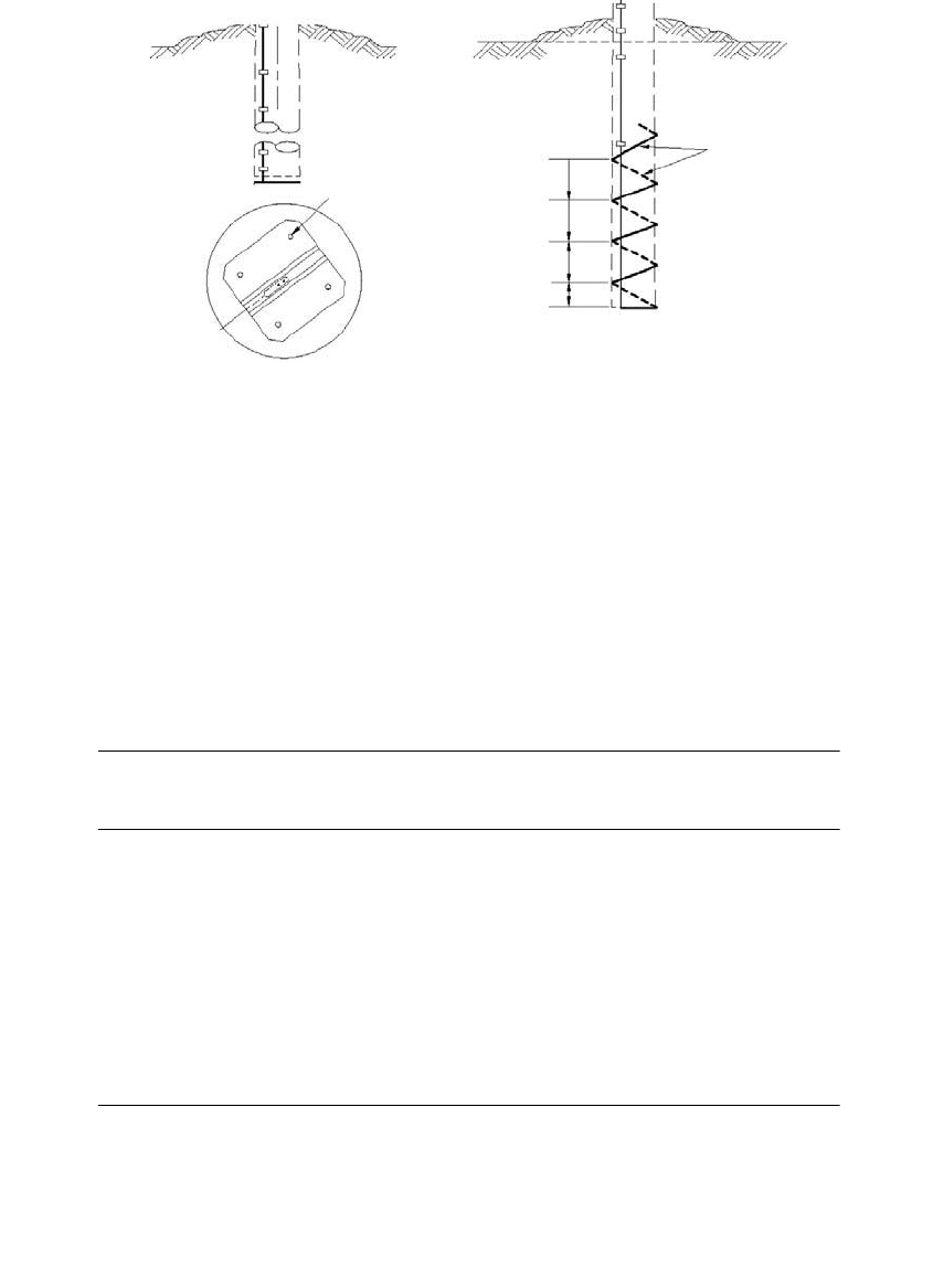
Two-pole grounding techniques, butt plates and wire wraps (see Figure
13.14) are available but have several deficiencies (Clapp, 1997). A driven
ground provides more than twice the surface area of a butt plate. Addition-
ally, pole movement can reduce the contact between the butt plate or wire
wrap and the earth, and the pole can draw moisture out of the soil enough
to increase its resistivity. The NESC only considers butt plates and wire wraps
as appropriate in areas with low ground resistivity (less than 30 W-m), and
even then, two such grounds must be used, and they must not be used as
the sole ground at transformer locations.
13.4.1 Soil Characteristics
Soil resistivity is the resistance of a certain volume of soil. Normally, resis-
tivity is specified in W-m, the resistance between opposite faces of cube of
TABLE 13.2
Resistance of Multiple Rods
Number of Rods
Multiplying
Factor
Total Resistance as a
Percentage of One Rod
2 1.16 58%
3 1.29 43%
4 1.36 34%
8 1.68 21%
12 1.80 15%
16 1.92 12%
20 2.00 10%
24 2.16 9%
Source: IEEE Std. 142-1991, IEEE Recommended Practice for
Grounding of Industrial and Commercial Power Systems.
1791_book.fm Page 670 Monday, August 4, 2003 3:20 PM
(C) 2004 by CRC Press LLC
Grounding and Safety 671
soil with a volume of 1 m
3
. Units of W-cm are also common — the resistance
between faces of a cube with a volume of a cubic centimeter: W-cm = 100 ¥
W-m.
Soil resistivities vary widely. Rich, moist organic soil may have a resistivity
of 10 W-m, while bedrock may have resistivities greater than 10
4
W-m. Resis-
tivity depends on the soil grain characteristics (size, variability, and density)
as well as moisture and chemical content. See Table 13.4 for typical values.
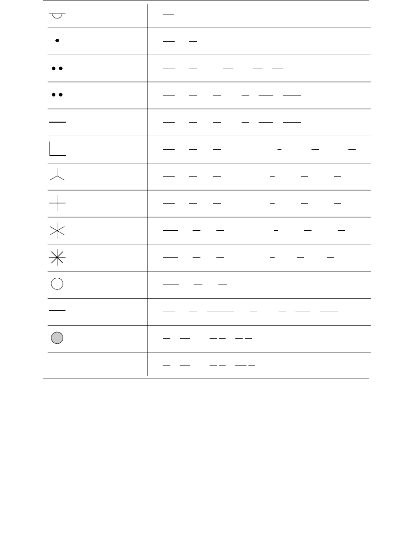
TABLE 13.3
Ground Electrode Resistance Calculations
Sources: Dwight, H. B., “Calculation of Resistance to Ground,” AIEE Transactions, vol. 55, pp.
1319–28, December 1936; IEEE Std. 142-1991. Copyright 1992 IEEE. All rights reserved.
Hemisphere
radius a
R =
ρ
2πa
One ground rod
length L,radius a
R =
ρ
2πL
ln
4L
a
1
Twoground rods
s > L;spacing s
R =
ρ
4πL
ln
4L
a
1+
ρ
4πs
1
L
2
3s
2
+
2L
4
5s
4
...
Twoground rods
s < L;spacing s
R =
ρ
4πL
ln
4L
a
+ln
4L
s
2+
s
2L
s
2
16L
2
+
s
4
512L
4
...
Buried horizontal wire
length 2L,depth s/2
R =
ρ
4πL
ln
4L
a
+ln
4L
s
2+
s
2L
s
2
16L
2
+
s
4
512L
4
...
Right-angle turn of wire
length of arm L,depth s/2
R =
ρ
4πL
ln
2L
a
+ln
2L
s
0.2373 + 0.2146
s
L
+0.1035
s
2
L
2
0.0424
s
4
L
4
...
Three-point star
length of arm L,depth s/2
R =
ρ
6πL
ln
2L
a
+ln
2L
s
+1.071 0.209
s
L
+0.238
s
2
L
2
0.054
s
4
L
4
...
Four-point star
length of arm L,depth s/2
R =
ρ
8πL
ln
2L
a
+ln
2L
s
+2.912 1.071
s
L
+0.645
s
2
L
2
0.145
s
4
L
4
...
Six-point star
length of arm L,depth s/2
R =
ρ
12πL
ln
2L
a
+ln
2L
s
+6.851 3.128
s
L
+1.758
s
2
L
2
0.490
s
4
L
4
...
Eight-point star
length of arm L,depth s/2
R =
ρ
16πL
ln
2L
a
+ln
2L
s
+10.98 5.51
s
L
+3.26
s
2
L
2
1.17
s
4
L
4
...
Ring of wire, depth s/2
diameter of ring D,
diameter of wire d
R =
ρ
2π
2
D
ln
8D
d
+ln
4D
s
Buried horizontal strip
length 2L,section a by b,
depth s/2, b < a/8
R =
ρ
4πL
ln
4L
a
+
a
2
πab
2(a + b)
2
+ln
4L
s
1+
s
2L
s
2
16L
2
+
s
4
512L
4
...
Buried horizontal round
plate, radius a,depth s/2
R =
ρ
8a
+
ρ
4πs
1
7
12
a
2
s
2
+
33
40
a
4
s
4
+
...
Buried vertical round
plate, radius a,depth s/2
R =
ρ
8a
+
ρ
4πs
1+
7
24
a
2
s
2
+
99
320
a
4
s
4
+
...
1791_book.fm Page 671 Monday, August 4, 2003 3:20 PM
(C) 2004 by CRC Press LLC
672 Electric Power Distribution Handbook
FIGURE 13.14
Butt plate and wire wrap grounds. (From RUS 1728F-803, Specifications and Drawings for 24.9/
14.4 kV Line Construction, United States Department of Agriculture, Rural Utilities Service, 1998.)
TABLE 13.4
Resistivity of a Variety of Soils along with Resistances of a 10-Foot Ground Rod
Soil
Average
Resistivity, WW
WW
-m
Resistance of a
5/8 in. (16 mm)
¥¥
¥¥
10 ft (3 m) Rod, WW
WW
Well graded gravel, gravel-sand mixtures, little or
no fines
600–1000 180–300
Poorly graded gravels, gravel-sand mixtures, little
or no fines
1000–2500 300–750
Clayey gravel, poorly graded gravel, sand-clay
mixtures
200–400 60–120
Silty sands, poorly graded sand-silts mixtures 100–500 30–150
Clayey sands, poorly graded sand-clay mixtures 50–200 15–60
Silty or clayey fine sands with slight plasticity 30–80 9–24
Fine sandy or silty soils, elastic silts 80–300 24–90
Gravelly clays, sandy clays, silty clays, lean clays 25–60
a
17–18
a
Inorganic Clays of high plasticity 10–55
a
3–16
a
a
Soils highly influenced by moisture.
Source: IEEE Std. 142-1991. Copyright 1992 IEEE. All rights reserved.
Plan View
Grounding Plate
Staple
3"
6"
6"
6"
Butt Plate Wire Wrap
1791_book.fm Page 672 Monday, August 4, 2003 3:20 PM
(C) 2004 by CRC Press LLC

Grounding and Safety 673
Soil resistivity often varies significantly with depth. In most areas, resis-
tivity improves significantly with depth as moisture increases, and normally,
grounds driven down to the water table provide a very good ground. In
other areas, an underlying bedrock significantly increases resistivity at lower
levels (and makes driving ground rods difficult). Several different layers of
soil with different resistivities may be present. A two-layer soil model is
often used for engineering analysis.
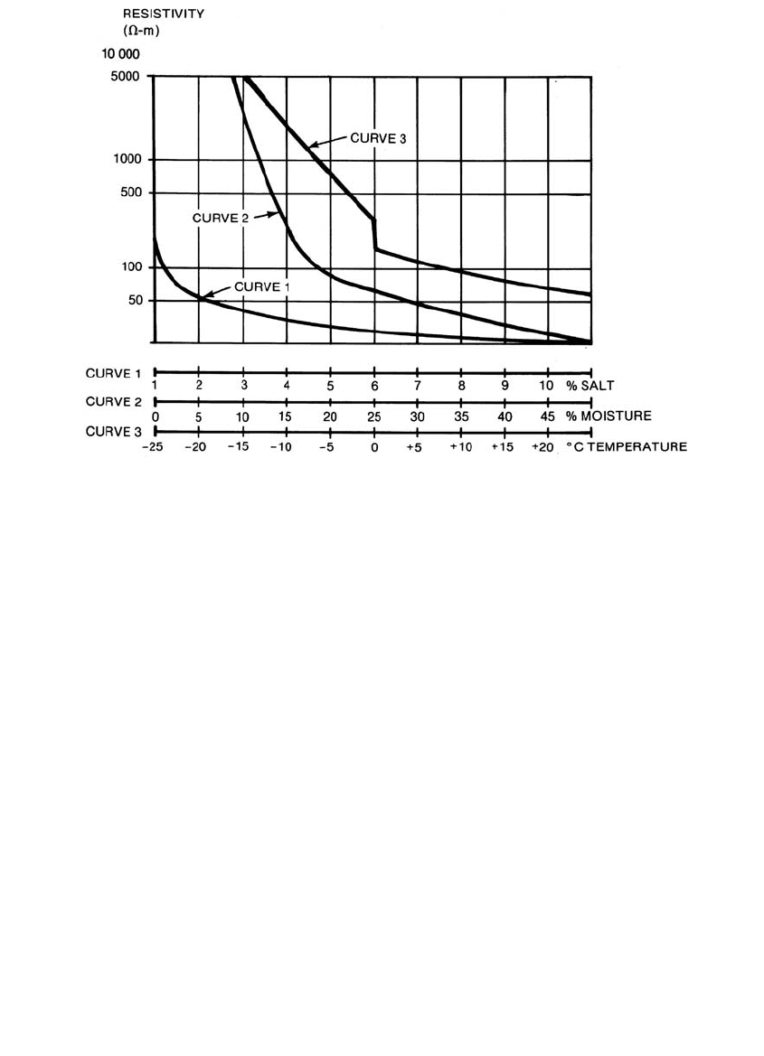
Soil resistivity is primarily affected by
• Moisture — Moisture is one of the main factors determining soil
resistivity. The dryer the soil, the higher the resistivity. Changes in
moisture level throughout the year are the biggest reason for the
change in ground electrode resistance. Once the moisture exceeds
22%, resistivity changes very little (IEEE Std. 142-1991).
• Temperature — Above the freezing point of water, temperature does
not impact resistivity significantly. Below freezing, resistivity rises
significantly.
• Salts — The presence of soluble salts significantly impacts the
resistivity.
Figure 13.15 shows these three main effects for different example soils.
These effects are somewhat interrelated and depend on the soil’s specific
characteristics.
One option to reduce ground electrode resistivity is to use chemical
treatments or backfills to reduce the soil resistivity near the electrode.
Bentonite backfills or salt treatments such as sodium chloride or calcium
chloride significantly reduce the soil resistivity. If soil treatments are used
to enhance ground rods, make sure to consider the effect on corrosion.
Some chemical treatments increase the metal corrosion rate. Also, consider
the environmental impacts and regulations. Most normal distribution
grounding needs outside of the substation do not warrant chemical
enhancement.
If a grounding electrode sustains significant current, the current may dry
out the surrounding soil and increase the resistance of the electrode. With a
multigrounded system, several grounds share current, but on systems with
isolated grounds, sustained current through a grounding electrode may
degrade the electrode’s resistance (another good reason to use multiple
grounding electrodes in parallel whenever possible).
The resistivity of soil is normally very linear, but for very high voltage
stresses, the soil breaks down; and arcing in the soil reduces the effective
resistivity. For a ground rod, the soil breaks down only when high current
flows into the rod, normally from lightning (a localized effect) or from faults
with very little sharing between ground rods. The breakdowns improve the
resistance of a grounding electrode.
1791_book.fm Page 673 Monday, August 4, 2003 3:20 PM
(C) 2004 by CRC Press LLC
674 Electric Power Distribution Handbook
13.4.2 Corrosion and Grounding Electrodes
Corrosion is a major consideration for grounding electrodes. Ground rods
are normally copper-clad steel or galvanized steel. Most grounding wires
are copper. Steel and aluminum corrode too quickly for grounding use. One
problem with copper is its attractiveness to thieves. In problem areas, copper-
clad steel has reduced thefts since it has less commercial value.
Mixing metals significantly increases corrosion. The problem is galvanic
corrosion. Different metals create an electrochemical battery in the soil. A
voltage develops between grounding electrodes made of different metals (or
between a grounding electrode and another metallic object in the ground).
When these electrodes are connected, current flows in the earth between the
metal objects, corroding one of the metals at a much higher-than-normal rate.
Galvanic corrosion between dissimilar metals can eat up grounding elec-
trodes. Galvanic corrosion operates on the same principal as a battery (bat-
teries release their energy with controlled corrosion). Pure metals are
unstable; they are found in nature as ores and must be refined to a pure
state. Metals corrode to return to their natural state. Iron dissolves in a
corrosive electrolyte and gives up electrons, forming a positive ion. Some of
the iron ions attach to free oxygen and become iron oxide (rust). At low
FIGURE 13.15
Effect of salt, moisture, and temperature on soil resistivity. (From IEEE Std. 80-2000. Copyright
2000 IEEE. All rights reserved.)
1791_book.fm Page 674 Monday, August 4, 2003 3:20 PM
(C) 2004 by CRC Press LLC
Grounding and Safety 675
corrosion rates, the metal reaches equilibrium with the surrounding electro-
lyte that prevents additional iron from releasing electrons. Two different
metals separated by an electrolyte (a conducting medium) have a voltage
difference between them as they give up electrons at different rates. If these
different metals are electrically connected together, current flows between
the metals and increases corrosion.
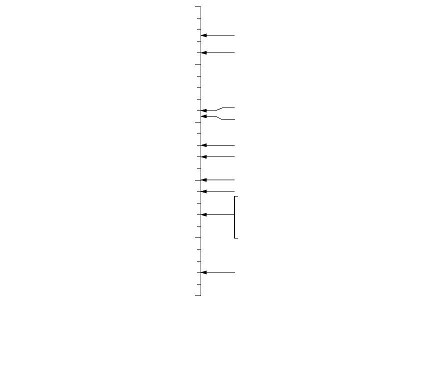
Consider a galvanized-steel ground rod next to a copper ground rod. The
galvanized rod is coated with zinc. The zinc releases more electrons into the
electrolyte, so it becomes positively charged relative to the copper rod. At
the zinc surface (the positive terminal, the anode), the flow of this dc current
dissolves the zinc at an increasing rate. At the copper rod (the negative
terminal), the galvanic circuit decreases the rate of corrosion. Figure 13.16
shows the galvanic series for several different metals. When dissimilar metals
form a galvanic circuit, the most anodic of the metal corrodes (corrosion
slows down, stops, or even reverses on the cathodic metal).
In fact, most corrosion occurs by the same action. An anode and a cathode
develop between different portions of a metal, and galvanic currents flow
FIGURE 13.16
Relative potentials of various metals in an electrolyte.
Pure magnesium
Magnesium Alloy
Zinc
Aluminum Alloy
Pure Aluminum
Mild Steel (Clean & Shiny)
Mild Steel (Rusted)
Cast Iron, Lead
Mild Steel in concrete,
Copper, Brass, Bronze,
Mill Scale on steel,
High silicon cast iron
Carbon, Graphite, Coke
-2.0
-1.0
0.0
Potential, volts
relative to Copper
Sulfate
(Cu-CuSO
4
)
Most Anodic
Most Cathodic
(Easiest to corrode)
1791_book.fm Page 675 Monday, August 4, 2003 3:20 PM
(C) 2004 by CRC Press LLC

676 Electric Power Distribution Handbook
between them, corroding the anode. One part of a metal may become anodic
to another in several ways based on differences in impurities in the metal,
mechanical stresses, and oxygen concentration.
Copper has naturally good properties that limit corrosion. When copper
corrodes, it becomes copper oxide; the copper-oxide layer greatly reduces
the corrosion rate and protects the underlying copper. Copper is normally
the most cathodic element, so it rarely corrodes because of dissimilar metals,
but it may help corrode other grounding electrodes.
A zinc coating on a steel ground rod (which is a galvanized steel rod)
provides corrosion protection for the rod. Zinc by itself is resistant to corro-
sion because it develops a self-protecting zinc-carbonate film that retards
further corrosion. In addition, the zinc provides galvanic protection to the
steel core. If part of the rod has exposed steel (due to cuts, scratches, or
corrosion of the zinc), the zinc acts as a very large anode to the small area
of exposed steel. Galvanic action reduces the corrosion on the exposed steel
(the cathode).
With lower soil resistivity, galvanic currents are higher, so grounding elec-
trodes corrode faster. Resistivity is the main soil parameter that determines
corrosion. Other factors that increase corrosion are very high or very low pH
levels, high water content, and the presence of chlorides (salts) and sulfates.
To limit excessive corrosion caused by different metals, avoid using dif-
ferent grounding rods (either stick with galvanized steel or with copper-clad
steel). Provide as much separation as possible between ground electrodes of
different metals. Consider the presence of guy anchors and other possible
buried wires including bare concentric neutral cables and water pipes. With
galvanized steel rods, use steel or aluminum pole ground leads. With copper-
clad steel rods, use copper down leads.
13.4.3 Resistance Measurements
The NESC does not specify how a ground measurement should be taken.
IEEE Std. 81-1983 documents several of the methods of measuring grounds.
Normally, on systems with a multigrounded neutral, the actual impedance
is not critical, so neither is the measurement. (Just make sure ground rods
are connected.) On systems without a multigrounded neutral, individual
grounds (and ground resistance checks) are more important.
Accurate ground electrode measurements of a concentrated electrode
(ground rods, anchors, or short strips of wire) are normally performed using
a three-point method (AEMC Instruments, 1998; Biddle Instruments, 1982;
IEEE Std. 81-1983). Two auxiliary ground probes are driven into the earth
forming a straight line with the test electrode. The tester injects current I
through the electrode under test and the outer auxiliary electrode. The tester
measures voltage V between the test electrode and the inner auxiliary elec-
trode. If the middle electrode is out of the influence of the outer two elec-
trodes, then the resistance of the test electrode is V/I.
1791_book.fm Page 676 Monday, August 4, 2003 3:20 PM
(C) 2004 by CRC Press LLC
Grounding and Safety 677
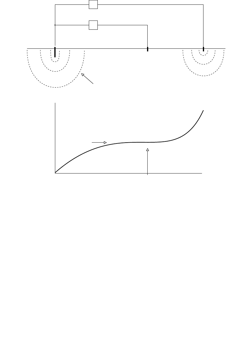
The fall of potential method is the most common three-point technique (see
Figure 13.17). It requires several measurements. Take several measurements
with the middle electrode at different locations between the test electrode
and the outer electrode. Plot the resistance vs. the distance, and pick the
resistance from the portion of the curve where resistance flattens out. The
point where the fall-of-potential curve flattens out is most likely near 62%
of the distance from the test electrode to the outer electrode. A simplified
version is just to measure near the 62% mark.
The three-point methods must be done with the ground electrode discon-
nected from the multigrounded neutral and connections to other grounds
that may interfere (including cable TV and telephone grounding connec-
tions). When disconnecting a grounding conductor from the multigrounded
neutral, crews should know that a significant potential can develop between
the neutral and the disconnected ground if a line-to-ground fault occurs
somewhere on the line.
FIGURE 13.17
Three-point ground-electrode measurement.
ZYX
V
I
Best estimate
62%0% 100%
Position of electrode Y
Resistance
measured
Current injected
Voltage measured
Area of influence of the
tested ground rod
Test
ground
rod
1791_book.fm Page 677 Monday, August 4, 2003 3:20 PM
(C) 2004 by CRC Press LLC

678 Electric Power Distribution Handbook
To have adequate spacing with the thee-point method, normally the outer
electrodes must be spaced at least 75 to 100 ft apart (23 to 30 m). Deeper
grounds or wider grounds (strips or multiple ground rods) require more
distance between the electrodes.
If an excellent ground is available nearby as a reference, the two-point
measurement technique is suitable. Just like an ohmmeter, the tester injects
current through the grounding electrode under test and the reference
ground. The resistance reading is the sum of both grounds, so if the reference
ground is very good (like a water piping system), the reading is predomi-
nantly the resistance of the test electrode. A multigrounded neutral can be
used as the ground reference but only if the frequency of the injected signal
is different from the standard power frequency (normal power-frequency
current flows can foul the ground reading). As with the three-point method,
the ground electrode must be disconnected from the multigrounded neutral.
A convenient ground electrode tester is a clamp-on device that tests a
grounding electrode by clamping around the grounding lead. The clamp-on
unit only works on electrodes connected to a very good ground like the
multigrounded neutral (it relies on the good ground). It works just like the
two-point test. The clamp-on is a current transformer that couples a voltage
to the grounding lead; the voltage is in the lower kilohertz range. The
resistance of the grounding electrode is the voltage divided by the current
(if all of the parallel grounds provide a low-impedance path, the resulting
impedance is only the grounding electrode).
The clamp-on ground-resistance tester more than adequately tests ground-
rod connections on systems with a multigrounded neutral. It is fast and
convenient, crews do not have to disconnect the ground rod, and it tests the
connector continuity. Since values of individual grounds are not as critical
on multigrounded-neutral systems, the clamp-on’s accuracy is good enough
for most grounding checks on distribution circuits.
Ground resistivity is normally measured using the four-point method.
Four electrodes of the same size are driven to the same depth in a straight
line with equal spacing between them. A tester injects current through the
outer two electrodes and measures the voltage between the inner two elec-
trodes. The distance between two electrodes determines the depth at which
the average resistivity is measured. If the electrode spacing is at least 20
times the electrode depth, the resistivity is
r = 2 p A R
where
r = earth resistivity, W-m
A = electrode spacing, m
R = resistance reading from the ground tester, W
Since the rod spacing determines the depth at which the resistivity is
measured, testing with multiple electrode separations shows how the soil
1791_book.fm Page 678 Monday, August 4, 2003 3:20 PM
(C) 2004 by CRC Press LLC