Rusko A., Thompson M. Power Quality in Electrical Systems
Подождите немного. Документ загружается.

v
s
i
s
v
L
I
L
+
−
(a)
I
L
v
s
(t)
i
s
(t)
t
(b)
1
Harmonic amplitude
of line current
35
Harmonic number (N)
(c)
7 9 11 13 15
1
/
3
1.0
1
/
5
1
/
7
1
/
9
1
/
11
1
/
13
1
/
15
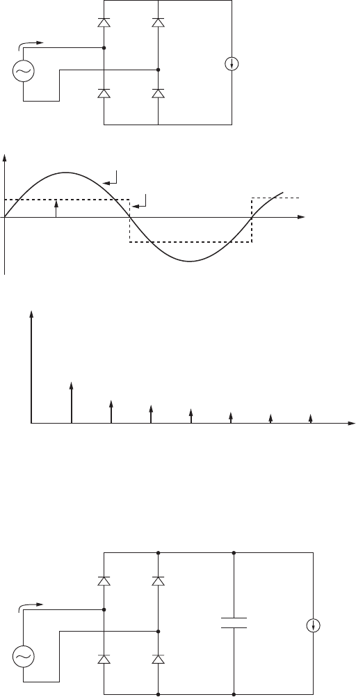
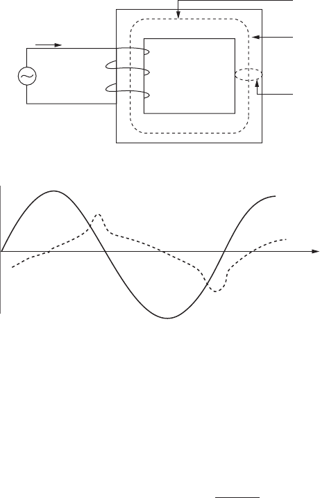
Figure 5.2 Full-wave rectifier with current source load. (a) The circuit. (b)
Waveforms, showing line-voltage and line current. Line current is a square
wave. (c) The spectrum of the line current, showing the characteristic 1/N
rolloff in spectral component amplitude with harmonic number.
v
s
i
s
v
BUS
C
BUS
I
L
+
−
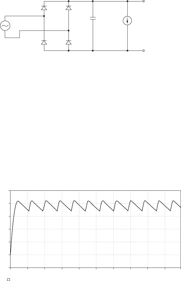
Figure 5.3 A full-wave rectifier with current source load, I
L
, and capac-
itive filter, C
BUS
.
Harmonic Current Sources 65
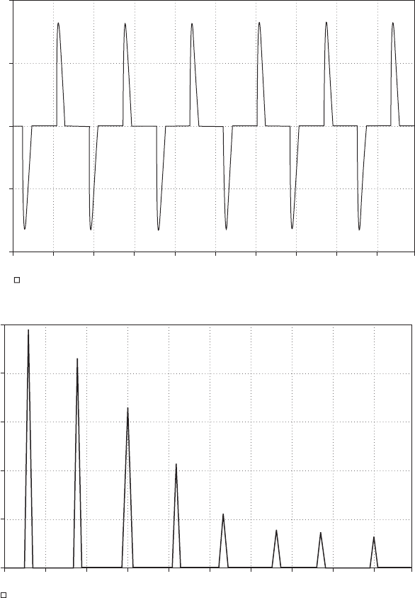
current source load and capacitive filter (Figure 5.4). In this case, we have
a 120-V AC source, a DC load of 5 A, and a capacitive output filter. With
a 1000 F bus capacitor, the load voltage ripple is about 25-V peak-peak
(Figure 5.5a). Note that the line current waveform has significant harmonic
distortion (Figure 5.5b and Figure 5.5c).
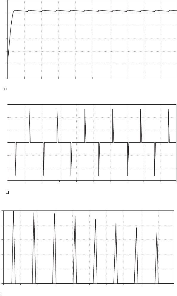
Next, we can reduce the load voltage ripple by increasing the filter
capacitor from 1000 µF to 10,000 µF. As shown in Figure 5.6a, note the
peak-peak load voltage ripple is reduced, but at the expense of higher
peak line current (Figure 5.6b) and higher levels of harmonic distortion
in the line current (Figure 5.6c).
In Table 5.1, we see the spectra in both cases, tabulated. The THD for
the rectifier with a 1000 F capacitive filter is approximately 140 per-
cent, and the peak-peak output ripple is 25 V. By increasing the filter
66 Chapter Five
v
s
vin+
D1
D3
D2
C
BUS
1000uF
D4
vin−
5A
I
L
vload+
vload−
Figure 5.4 A full-wave rectifier with current source load and capacitive filter
showing PSPICE circuit with bus capacitor 1000 µF and a load that draws a
DC current of 5 A.
−40 V
0 ms
10 ms
V(vload+)
− V(vload−)
20 ms 30 ms 40 ms 50 ms
Time
(a)
60 ms 70 ms 80 ms 90 ms 100 ms
80 V
40 V
0 V
120 V
160 V
200 V
Figure 5.5 A full-wave rectifier with current source load and capacitive filter. (a) The
waveform of the load voltage, which has a ripple due to the load current and the finite
value of the filter capacitor. (b) The line current, which is very “spikey.” (c) The spectrum
of the line current.
capacitor to 10,000 F, we reduce the output ripple to approximately
4 V, but the line current is much more spikey and the THD of the line
current is approximately 265 percent. This result illustrates one trade-off
with this type of rectifier.
Harmonic Current Sources 67
−40 A
100 ms
110 ms 120 ms 130 ms 140 ms 150 ms
(b)
160 ms 170 ms 180 ms 190 ms 200 ms
−20 A
0 A
20 A
40 A
I(vs)
0 A
0 Hz 0.1 KHz 0.2 KHz 0.3 KHz 0.4 KHz 0.5 KHz
Frequency
(c)
0.6 KHz 0.7 KHz 0.8 KHz 0.9 KHz 1.0 KHz
4 A
2 A
6 A
8 A
10 A
I(vs)
Figure 5.5 (Continued)
−40 V
0 ms
10 ms
V(vload+)
− V(vload−)
20 ms 30 ms 40 ms 50 ms
Time
(a)
60 ms 70 ms 80 ms 90 ms 100 ms
80 V
40 V
0 V
120 V
160 V
200 V
Capacitor voltage
−150 A
I(Vs)
130 ms120 ms110 ms100 ms 140 ms 150 ms
Time
(b)
160 ms 170 ms 180 ms 190 ms 200 ms
0 A
−50 A
−100 A
50 A
100 A
150 A
0 A
0 Hz
0.1 KHz 0.2 KHz 0.3 KHz 0.4 KHz 0.5 KHz
Frequency
(c)
0.6 KHz 0.7 KHz 0.8 KHz 0.9 KHz 1.0 KHz
4 A
2 A
6 A
8 A
10 A
I(Vs)
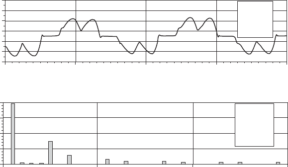
Figure 5.6 A full-wave rectifier with current source load and increased capacitive filter to
10,000 µF. (a) The waveform of the load voltage, which has a reduced ripple compared to
the 1000 µF case. (b) The line current, which is very “spikey.” (c) The spectrum of the line
current.
68
Three-Phase Rectifiers
The six-pulse rectifier
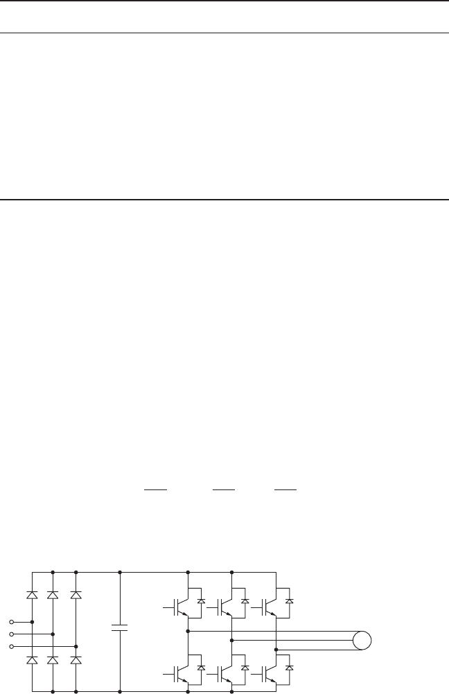
A typical application using a three-phase, six-pulse rectifier is an
adjustable speed drive (Figure 5.7). Three-phase power (labeled phases
a, b, and c) is full-wave rectified by the six-pulse rectifier. The rectified
voltage is filtered by the high-voltage bus capacitor, C
bus
, generating a
DC voltage, which is used by the subsequent inverter. The three-phase
inverter generates the three-phase currents necessary to drive the motor.
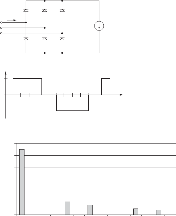
A six-pulse rectifier is shown in Figure 5.8a. Assuming that the load
approximates a current source (with very large load inductance), the line
current drawn from the rectifier shows a THD of 31 percent, and an
absence of a third-harmonic and all triplen harmonics (Figure 5.8b). We
can show that the harmonic amplitudes of the phase currents of the ideal
six-pulse rectifier with current source load, I
L
, are [5.1]:
The spectrum of the AC line currents is shown in Figure 5.8c.
4
Np
I
L
sina
Np
2
b sina
Np
3
b
Harmonic Current Sources 69
TABLE 5.1 Results of the PSPICE Simulation Showing the Fourier Spectrum of Line
Current for Example 5.1
Harmonic current with Harmonic current with
Harmonic number 1000 µF filter capacitor 10,000 µF filter capacitor
1 10.0 10.0
3 9.4 10.0
5 6.9 9.8
7 4.8 9.5
9 3.0 9.0
11 2.2 8.25
13 2.1 7.75
15 2.0 7.0
17 1.65 6.5
19 1.35 6.3
21 1.25 5.0
23 1.2 4.5
25 1.1 3.8
27 1.0 3.3
M
a
Diode
rectifier
DC link bus
capacitor PWM inverter
Motor
b
c
Figure 5.7 Adjustable speed drive for a three-phase induction motor.
The twelve-pulse rectifier
The twelve-pulse rectifier (Figure 5.9a) is comprised of two six-pulse rec-
tifiers fed from separate transformers. One six-pulse is fed from a Y/Y
transformer, and the other is fed from a ∆/Y transformer. The two recti-
fier voltages are phase shifted 30 from one another. The resultant phase
current waveform (Figure 5.9b) more closely mimics an ideal sine wave
70 Chapter Five
(a)
a
b
c
I
L
V
L
i
a
+
−
I
L
i
a
(t)
−I
L
90° 180° 270°
(b)
ω
360°
Spectrum for ideal three-phase bridge
0.00
0.20
0.40
0.60
0.80
1.00
1.20
1 2 3 4 5 6 7 8 9 10 11 12 13 14
Harmonic number (N)
(c)
Amplitude
Figure 5.8 A six-pulse rectifier. (a) The circuit. (b) The line current for L/R period
of line frequency. (c) The spectrum of the line current, assuming I
L
1.
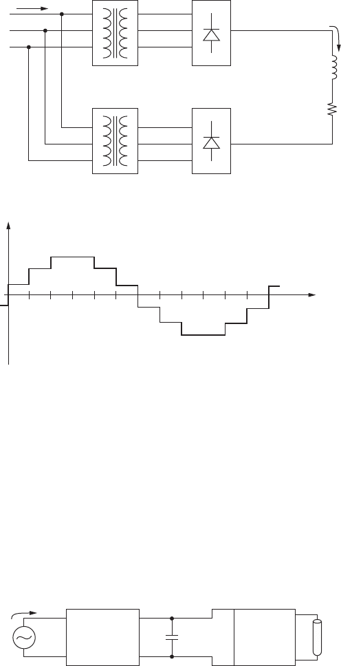
than in the six-pulse case. This is because the 12-pulse topology elimi-
nates the 5th, 7th, 17th, and 19th harmonics, leaving the 11th, 13th,
23rd, and 25th harmonics.
High-Frequency Fluorescent Ballasts
High-frequency fluorescent ballasts (Figure 5.10) are a rich source of high-
frequency voltage and current harmonics. The line waveform is rectified
by a power-factor corrected boost converter. The rectified DC voltage
powers a high-frequency inverter that generates the high voltage needed
Harmonic Current Sources 71
(a)
a
b
c
i
a
Y/Y
Six-pulse
rectifier
∆/Y
Six-pulse
rectifier
L
I
L
R
LOAD
(b)
i
a
(t)
t
Figure 5.9 A twelve-pulse rectifier. (a) The circuit. (b) The line current for
phase-a for L/R period of line frequency.
Inverter Lamp
C
BUS
v
s
Power
factor
correction
boost
i
s
Figure 5.10 High-frequency switching fluorescent ballast with a power
factor correction front end.
by the lamp. The power factor correction circuit switches at a frequency
much higher than line frequency. Usually, the line side has passive filter-
ing to help reduce the high-frequency harmonics drawn from the AC line.
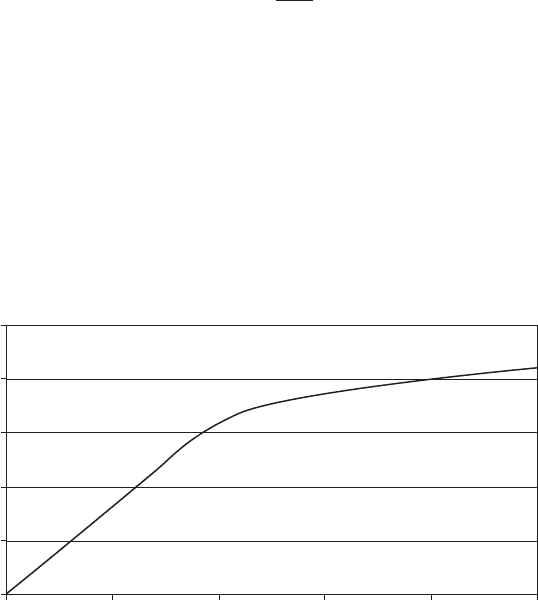
Transformers
One source of harmonics using transformers with iron cores is the non-
linear B/H curve associated with these devices. Figure 5.11 shows a
representative B/H curve for electrical steel that may be used in a trans-
former core. Not shown here, purposely, is the hysteresis loop, since for
simplicity we’ll consider a single-valued B/H curve. Note that the core
material saturates at a magnetic flux density B ~ 2 Tesla or so.
The slope of the B/H curve at any point is the magnetic permeability
of the core material, or
From this equation, note that as the core material saturates, the mag-
netic permeability decreases. For economic reasons, power transformers
are often operated at a relatively high magnetic flux density, above the
B/H curve “knee.”
Shown in Figure 5.12a is a magnetic circuit without an airgap. The
magnetic circuit is comprised of N turns, the core material has magnetic
permeability m
c
, and the cross-sectional area of the core is A with a char-
acteristic length, l
c
, which is the mean path length of the flux lines inside
m
c
5
dB
dH
72 Chapter Five
B/H curve for electrical steel
0
0.5
1
1.5
2
2.5
1 10 100 1000 10000 100000
H, A-turns/m
B, Tesla
Figure 5.11 A representative nonlinear B/H curve.
the core. From magnetic circuit analysis, we can find the inductance of this
structure as:
We’ll now assume that we excite this circuit with sufficient volt-seconds
so the core material begins saturation. Equivalently, saturation means
the permeability of the core decreases with a corresponding decrease
in the inductance at high current levels. This nonlinear property of
the magnetic core requires that the current has harmonic distortion,
as shown in Figure 5.12b.
Other Systems that Draw Harmonic Currents
High-frequency switch-mode power supplies are covered extensively in
Chapter 7. Other sources of harmonic currents are adjustable speed
drives (ASDs), motors, and arc furnaces. Figure 5.13 illustrates the typ-
ical line current and spectrum for an adjustable speed drive.
L 5
m
c
AN
2
l
c
Harmonic Current Sources 73
Mean path length l
c
Area A
c
Permeability µ
c
v(t)
N
(a)
i(t)
v(t)
i(t)
(b)
t
Figure 5.12 An inductor that draws nonlinear current. (a) The circuit. The induc-
tor has N turns; a mean path length, l
c
; core permeability, m
c
; and a core cross-
sectional area, A
c
. (b) The waveforms of inductor voltage, v(t), and the inductor
current, i(t).
Summary
In this chapter, we’ve covered equipment that generates harmonics, such
as rectifiers, transformers, and switching power supplies. Harmonics
can cause many detrimental effects, including resonances with power
factor correction capacitors, the heating of neutral conductors, the false
tripping of relaying equipment, and the heating of capacitors. In the
next chapter, we’ll discuss power harmonic filters.
References
[5.1] R. W. Erickson and D. Maksimovic, Fundamentals of Power Electronics, second edi-
tion, Springer, 2001.
[5.2] IEEE, “IEEE Recommended Practice for Monitoring Electric Power Quality,” IEEE
Std. 1159-1995.
74 Chapter Five
−50
−30
−10
10
40 50 60
Time (ms)
70 80
30
50
70
Mpr : 313.517
Mr : 171.304
Avg : 33.5352
Acr : 315.907
RVS : 54.3862
Of : 4.87557
FF : 1.52507
0
5
10
0 600
ASD input current
Frequency (Hz)
Current (A)
Current (A)
1200 1800
15
20
Freq : 50
Fwrd : 19.4713
THD : 41.0054
RMSA : 315.907
RMS : 31.0448
ASUM : 37.3558
TIF : 427.213
IT : 8990.51
Figure 5.13 The input line current and spectrum for an adjustable speed drive [5.2].
[© 1995, IEEE, reprinted with permission]