Rusko A., Thompson M. Power Quality in Electrical Systems
Подождите немного. Документ загружается.

impedance reduces to Z R. For other than resonance, the magnitude of
Z is given by:
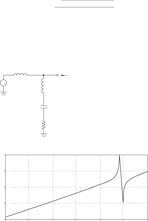
The impedance of a single-tuned section tuned to 300 Hz, or v
r
1884
rad/s, is shown in Figure 6.11b. Two values of R are shown, R 0.01 Ω
and 0.1 Ω, which becomes the impedance at resonance. The impedances
of the L and C at resonance are selected for the example as 0.94 Ω.
Example 6.1: Series resonant filter. A series resonant filter used on an AC
line is shown in Figure 6.12a. We see the series resonant circuit L
f
, C
f
,
ZZ Z 5
2sRCvd
2
1 s1 2 LCv
2
d
2
vC
Power Harmonic Filters 85
L
L
f
500 uH
220 uH
Z
C
f
563 uF
0.01
R
(a)
v
s
Vo
Ls
+
−
Figure 6.12 A series-tuned filter section example. (a) The basic circuit. (b) The magni-
tude of the output impedance Z at the PCC.
20
0
1.0 Hz 3.0 Hz 10 Hz 30 Hz
Frequency
(b)
Output impedance Z
100 Hz 300 Hz 1.0 KHz
−20
−40
−60
and R
1
that has been added to the line. Inductor L
s
models the inductance
of the source. The magnitude of the impedance Z at the output node is
We see that the transfer function has a minimum at the series resonant
frequency of the filter components. There is also a peak at a frequency
lower than the series resonant frequency at the frequency where (L
s
L
f
)
resonates with the capacitor. A PSPICE simulation of the fifth-harmonic
filter showing the magnitude of the impedance Z is shown in Figure 6.12b.
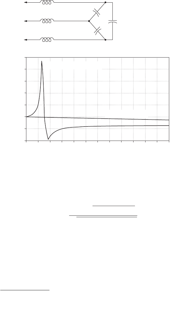
A harmonic filter designed to attenuate fifth-harmonic components for
an adjustable speed drive
4
application is shown in Figure 6.13a [6.4]. In
ZZ Z<
svL
s
d 2s1 2 sL
f
C
f
v
2
dd
2
2s1 2 ssL
f
1 L
s
dC
f
v
2
dd
2
86 Chapter Six
480-V bus
(a)
3.50
2.50
1 3 5 7
Harmonic number
Magnification of harmonic current from
ASDS
(b)
9 11 13 15 17 19 21 23 25
1.50
2.00
3.00
1.00
0.50
0.0
500 kVAr tuned cap bank
No capacitor bank
4
In the power world, capacitors are often specified not by the capacitance value, but by
the VAr rating. VAr stands for volt-amperes reactive. The VAr rating of a capacitor is found
using VA
r
(V) (A) (V ) (V/C) (V
2
/C).
Figure 6.13 A three-phase filter [6.4]. (a) The circuit. (b) The effect of the capac-
itor bank on the voltage at the PCC.
[© 1999, IEEE, reprinted with permission]
Power Harmonic Filters 87
Z
1
I
h
Converter Filter Linear loud
Z
2
Z
3
Z
L
PCC
Z
S
+
Utility source
V
h
+
−
−
I
hc
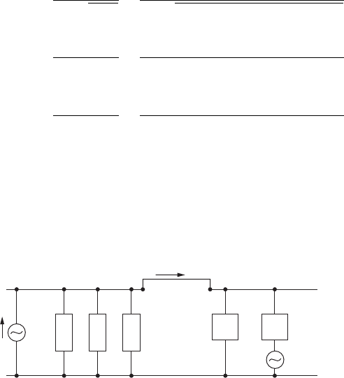
Figure 6.14 A multiple section filter. The harmonic generating load is
modeled as a current source of value I
h
.
Figure 6.13b, we see the characteristic peak and valley of this type of
harmonic filter. Harmonic filters have also been used to reduce har-
monic interference with telephone systems.
Multisection filters
We can use multiple harmonic filter sections (Figure 6.14) to reduce the
effects of higher-order harmonics generated by nonlinear loads con-
nected to the PCC. The filter is designed to attenuate higher-order
harmonics such as the 5th, 7th, and 11th that are generated by the
nonlinear load. Generally, the filter components are tuned a few percent
below the harmonic frequency [6.2] to account for component varia-
tions, temperature variations, component aging, and system changes.
Figure 6.15a shows a filter designed to attenuate the 5th, 7th, and
11th harmonics. In this design example, each filter section is tuned
4 percent below the filtered harmonic. The series resonant frequencies
of the three series resonant circuits are
These are the frequencies at which we expect significant attenua-
tion, as evidenced in the PSPICE plot of Figure 6.15b. We also see peak-
ing at frequencies below the three series-resonant frequencies. This is
characteristic of harmonic single-tuned filters and we need to be
f
3
5
1
2p 2L
3
C
3
5
1
2p 2s500 3 10
26
ds126 3 10
26
d
5 634 Hz
f
2
5
1
2p 2L
2
C
2
5
1
2p 2s500 3 10
26
ds312 3 10
26
d
5 403 Hz
f
1
5
1
2p 2L
1
C
1
5
1
2p 2s500 3 10
26
ds611 3 10
26
d
5 288 Hz
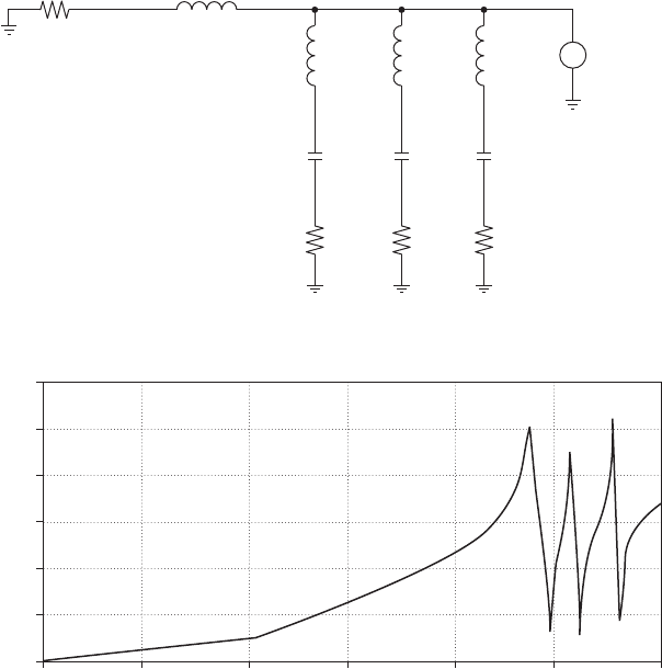
mindful to design our filters so these peaks do not occur at frequencies
where harmonic currents exist.
Example 6.2: Series-tuned filters. Let’s now consider an example where
we’ll design a filter to attenuate harmonic currents drawn from the line
to comply with IEEE-519. Note the circuit of Figure 6.16a, where the
source is 277 V, line-to-neutral. The fundamental load current at 60 Hz
is I
L
100 A. This load also draws fifth-harmonic current I
5
20 A and
seventh-harmonic current I
7
15 A.
88 Chapter Six
(a)
L1
500 uH
220 uH0.01
L2
500 uH
C1
611 uF
C2
312 uF
R1
0.01
R2
0.01
L3
500 uH
I1
C3
126 uF
R3
0.01
Utility source Filter PCC
+
−
Rline Ls vpcc
20
0
10
−20
1.0 Hz 3.0 Hz 10 Hz 30 Hz
Frequency
(b)
Impedance Z at the PCC
100 Hz 300 Hz 1.0 KHz
−10
−30
−40
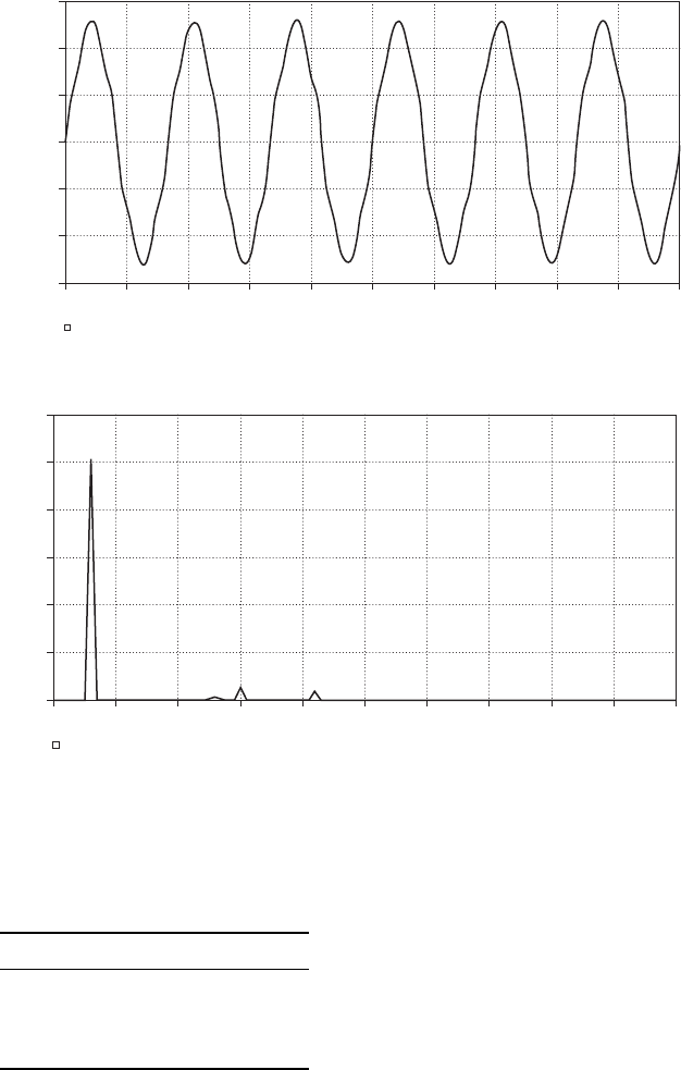
Figure 6.15 A harmonic multisection filter. This filter provides mimima at the 5th, 7th,
and 11th harmonics. The line is modeled as an ideal voltage source, with a line induc-
tance of 220 ΩH and a line resistance of 0.01 . (a) The circuit. (b) A PSPICE simula-
tion showing the impedance at the PCC.
First, we need to determine what the IEEE-519 limits are for line har-
monic currents, using Table 10.3 (Figure 6.5). Note that the harmonic
current limits depend on the ratio I
SC
/I
L
, where I
SC
is the short-circuit
current at the PCC, and I
L
100 A is the fundamental load current. For
Power Harmonic Filters 89
Figure 6.16 The circuit for Example 6.2. (a) The circuit. (b) The line current. (c) The spec-
trum of the line current.
(a)
+
−
+
−
v
s
277 V
100 A 20 A 15 A
1
7
1
5
I
L
100 uH
j(37.7 mΩ)
Ls
PCC
+
−
+
−
120 A
80 A
40 A
0 A
−40 A
−80 A
−120 A
10 s 10 ms
20 ms 30 ms 40 ms 60 ms 80 ms 90 ms50 ms
Time
(b)
70 ms 100 ms
I(Ls)
120 A
100 A
80 A
60 A
40 A
20 A
0 A
0Hz 0.1KHz 0.2KHz 0.3KHz 0.4KHz 0.6KHz 0.8KHz 0.9KHz0.5KHz
Frequency
(c)
0.7KHz 1.0 KHz
I(Ls)
this circuit, the short circuit current is
Therefore, the ratio I
SC
/I
L
7348/100 73.48. From Table 10.3 of
IEEE-519, we see that the maximum current harmonic (for harmonics
less than the 11th) is 10 percent of the fundamental. Therefore, both the
5th and 7th harmonics violate this standard. We also violate the TDD
specification, which is 12 percent. In Figure 6.16b and Figure 6.16c, we
see the current waveform and spectrum, respectively.
Figure 6.17a shows the system with two series-tuned filters added.
L
f1
and C
f1
are tuned to 290 Hz, and L
f2
and C
f2
are tuned to 407 Hz.
The line current is shown in Figure 6.17b, where we see that the
harmonic content has been significantly reduced. A spectrum of the
line current (Figure 6.17c) shows that we meet IEEE-519 limits, both
for the amplitude of the harmonics and the total harmonic distortion.
Example 6.3: another filter design. A hypothetical nonlinear load draws
fundamental (60 Hz) and harmonic currents from an AC source. The AC
source is modeled as an ideal 277-V source in series with a 220-H
inductance and a line resistance of 0.01 Ω, which includes the effect of
a step-down transformer. The load draws harmonic currents with the
strength shown in Table 6.1. We’ll next find the load voltage with and
without the harmonic filter of Figure 6.15 using PSPICE.
I
SC
5
V
s
X
L
s
5
277
s2dspds60ds10
24
d
5 7348 A
90 Chapter Six
(a)
Lf 1
500 uH
Lf 2
500 uH
Cf 1
500 uF
Cf 2
306 uF
Rf 1
0.01 Ω
Rf 2
0.01 Ω
Ls
+
−
+
−
vs
277 V
100 A 20 A 15 A
I
7
I
5
I
L
PCC
+
−
+
−
Figure 6.17 The circuit for Example 6.2, with series-tuned filters added
(a) The circuit. (b) The line current. (c) The spectrum of the line current.
Power Harmonic Filters 91
120 A
80 A
40 A
0 A
−40 A
−80 A
−120 A
300 ms 310 ms
320 ms 330 ms 340 ms 360 ms 380 ms 390 ms350 ms
Time
(b)
370 ms 400 ms
i(ls)
120 A
100 A
80 A
60 A
40 A
20 A
0 A
0 Hz 0.1 KHz
0.2 KHz 0.3 KHz 0.4 KHz 0.6 KHz 0.8 KHz 0.9 KHz0.5 KHz
Frequency
(c)
0.7 KHz 1.0 KHz
i(Ls)
Figure 6.17 (Continued)
TABLE 6.1 Harmonic Currents for
Example 6.1
Harmonic number Value (Amps)
1 100
550
725
11 15
92 Chapter Six
(a)
Ls R line
220 uH 0.01
+
−
Vs
+
−
+
−
+
−
+
−
l
1
l
5
l
7
l
11
Vo
400 V
200 V
0 V
−200 V
−400 V
0 s 10 ms
20 ms 30 ms 40 ms 60 ms 80 ms 90 ms50 ms
(b)
70 ms 100 ms
V(Vo)
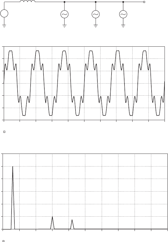
Figure 6.18 The original system of Example 6.3. (a) The circuit. (b) The PSPICE simula-
tion showing the load voltage. (c) The spectrum of the load voltage.
First, we’ll model the system in PSPICE using the circuit of Figure 6.18a.
We can calculate the expected total harmonic distortion of the load volt-
age using the calculated values shown in Table 6.2. We have found the
magnitude of the line impedance at each harmonic frequency, and
then the voltages at the harmonics are calculated. Note that the
expected rms output voltage at the fundamental is 277 8.4 268.6 V
due to the drop across the line reactance at 60 Hz. So, the THD of the
load voltage is
THD 5
220.7
2
1 14.5
2
1 13.7
2
268.6
5 10.7%
Power Harmonic Filters 93
The PSPICE simulation result (Figure 6.18b) shows the result in the
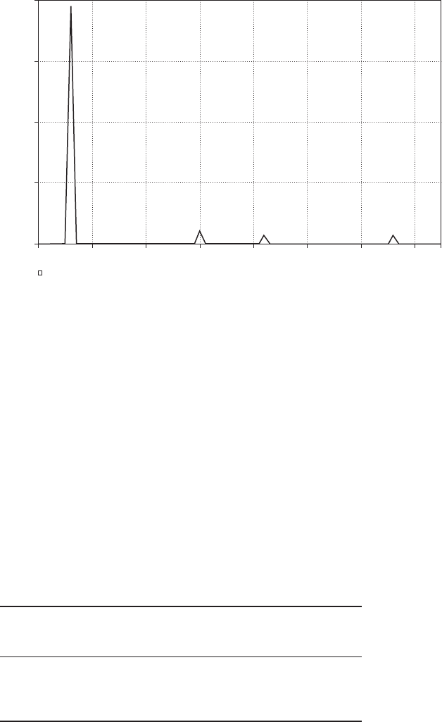
time domain. In the frequency domain, we see harmonic distortion, as
expected, at the 5th, 7th, and 11th harmonics, as shown in the Fourier
spectrum of Figure 6.18c.
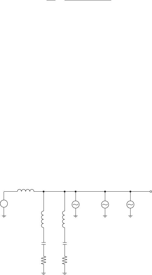
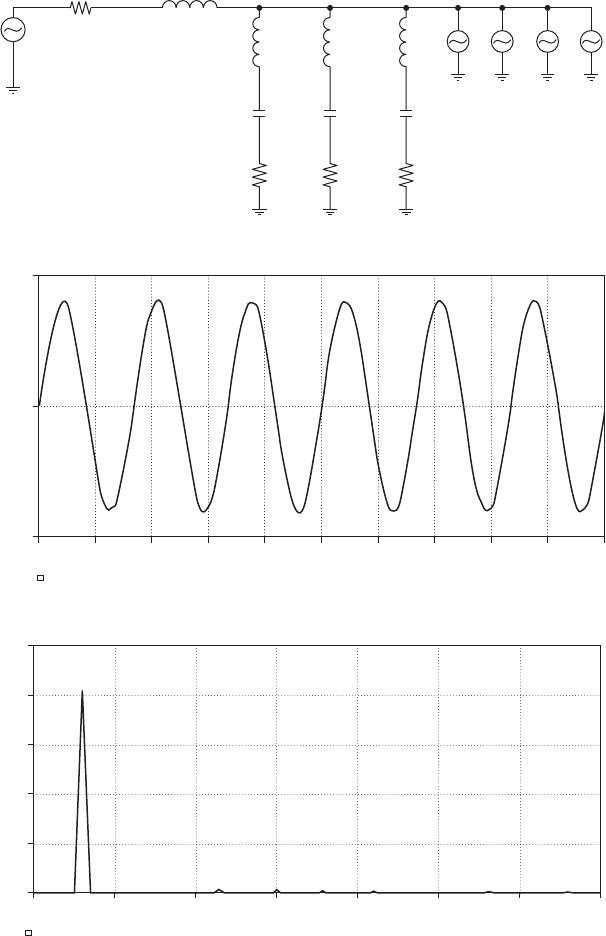
We can reduce the harmonic distortion in the load voltage using the
circuit of Figure 6.19a. The three series-resonant circuits are tuned
4 percent below the 5th, 7th, and 11th harmonics. In Figure 6.19b, we
see an improvement in the waveform distortion. Looking at the spectrum
(Figure 6.19c), note that the 5th, 7th, and 11th harmonic distortion has
been largely eliminated and that the resultant THD of the load voltage
in the filtered case is roughly 1 percent.
TABLE 6.2 Calculating THD for Example 6.3
Magnitude of line
impedance at Voltage drop at
Harmonic number harmonic frequency harmonic frequency
1 0.08 Ω 8.4
5 0.41 Ω 20.7
7 0.58 Ω 14.5
11 0.91 Ω 13.7
400 V
300 V
200 V
100 V
0 V
0 Hz 100 Hz 200 Hz 300 Hz 400 Hz
Resultant Fourier spectrum of system without filter
600 Hz500 Hz
Frequency
(c)
700 Hz
V(Vo)
Figure 6.18 (Continued)
94 Chapter Six
(a)
L3
500 uH
C3
306 uF
R3
0.01 Ω
L2
500 uH
C2
312 uF
R2
0.01 Ω
L1
500 uH
C1
611 uF
R1
0.01 Ω
Ls
vpcc
PCCFilterUtility source
+
−
v
s
220 uH
0.01 Ω
Rline
+
−
+
−
+
−
+
−
l
1
l
5
l
7
l
11
500 V
0 V
−500 V
100 ms 110 ms
120 ms 130 ms 140 ms 160 ms 180 ms 190 ms150 ms
Time
(b)
170 ms 200 ms
v(vpcc)
500 V
400 V
300 V
200 V
100 V
0 V
0 Hz 100 Hz 200 Hz 300 Hz 400 Hz 500 Hz 600 Hz 700 Hz
v (vpcc)
Frequency
(c)
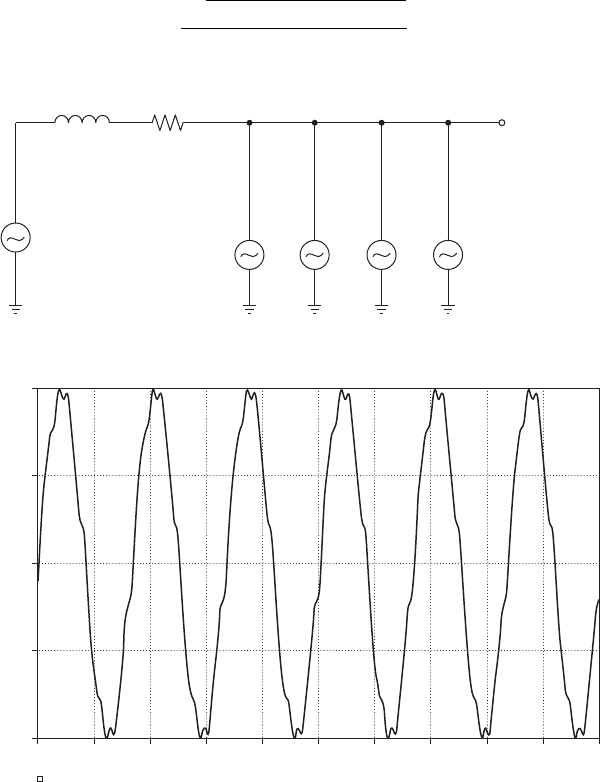
Figure 6.19 The system of Example 6.3 with single-tuned sections added. (a) The circuit.
(b) The PSPICE simulation showing the load voltage. (c) The spectrum of the load voltage