Rusko A., Thompson M. Power Quality in Electrical Systems
Подождите немного. Документ загружается.

Harmonics and Interharmonics 55
0 0.005 0.01 0.015 0.02 0.025 0.03
−1.5
−1
−0.5
0
0.5
1
1.5
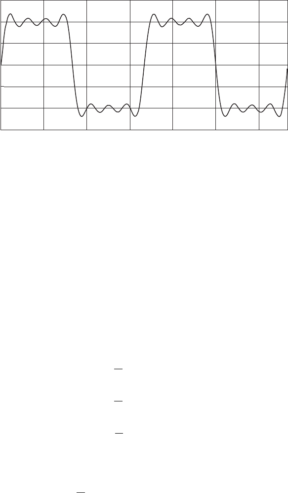
Truncated square wave
Figure 4.15 A truncated square wave Fourier series result with first, third, fifth, and
seventh harmonics. The THD is 41.4 percent.
Example 4.2: Neutral current in three-phase systems. In this example, we’ll
show that the neutral current in three-phase systems with balanced
linear loads is zero. Shown in Figure 4.16a is a balanced three-phase
system with linear resistive loads. The three-phase voltages have the
form:
where each of the voltages (v
an
, v
bn
, v
cn
) is the phase voltage to neutral.
The phase currents are:
The neutral current is the vector sum of the three-phase currents.
i
n
5 i
a
1 i
b
1 i
c
5 a
V
R
b[sinsvtd1 sinsvt 2 1208d 1 sinsvt 2 2408d] 5 0
i
c
5 a
V
R
bsinsvt 2 2408d
i
b
5 a
V
R
bsinsvt 2 1208d
i
a
5 a
V
R
bsinsvtd
v
cn
5 V sinsvt 2 2408d
v
bn
5 V sinsvt 2 1208d
v
an
5 V sin svtd
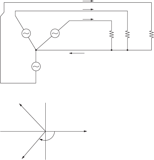
Referring to the phase current phasor diagram (Figure 4.16b), note
that the neutral current indeed does sum to zero in this special case of
balanced, linear loads.
Example 4.3: Nonlinear loads. Power-line harmonics are created when
nonlinear loads draw nonsinusoidal current from a sinusoidal volt-
age source. In this example, we’ll show how nonlinear loads can
result in high neutral currents in three-phase systems. These har-
monics can result in neutral current that exceeds the individual
phase current.
Let’s consider a three-phase system where the loads on each of the
three phases are balanced but nonlinear. Therefore, the magnitudes of
the current in each phase are equal to one another. In most three-phase
systems with nonlinear loads, the odd harmonics dominate the even
56 Chapter Four
−120°
i
a
i
b
(b)
i
c
i
n
a
c
b
RR R
i
a
i
c
i
b
(a)
Figure 4.16
A balanced three-phase system. (a) A circuit showing bal-
anced resistive loads. (b) A phasor diagram of the neutral currents.
harmonics. Mathematically, we can express the current in phases a, b,
and c as:
with j 1, 2, 3, . . .. We see that I
1
is the amplitude of the fundamen-
tal, and the I
n
s are the amplitudes of the odd harmonics. There are
phase shifts, denoted by u
n
, for each of the harmonics as well.
To further simplify matters, let’s next consider a load that produces
only third-harmonic currents. In many three-phase circuits, the third
harmonic is the dominant harmonic. In three-phase systems where there
are third-harmonic currents, the 120-degree phase shift for the funda-
mental results in a 360-degree phase shift for the third harmonic. This
means that the third-harmonic currents from each phase conductor are
in phase with one another, and that the neutral current is equal to the
sum of the third-harmonic amplitudes from each of the phases, or:
where I
h3
is the amplitude of the third-harmonic current in each
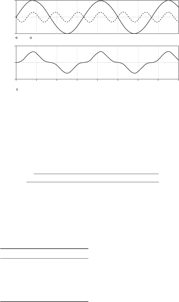
phase. We’ll next examine this phenomenon graphically, using a
system that has a third-harmonic amplitude on each phase that is
30 percent of the fundamental. Shown in Figure 4.17 (top traces) are
the first and third harmonics of this phase conductor. Note that the peak
of the 60 Hz fundamental is 1.0 amps, and the peak of the 180 Hz third
harmonic is 0.3 amps. Shown in the bottom trace of Figure 4.17 is the
total phase-a current, which is the vector sum of the fundamental and
third harmonic.
Next, we add up the sum of the phase currents to get the total neutral
current.
i
n
5 i
a
1 i
b
1 i
c
5 0.9 sins3vtd
i
c
5 s1.0d sinsvt 2 2408d 1 s0.3d sins3vt 2 s3d 3 2408d
i
b
5 s1.0d sinsvt 2 1208d 1 s0.3d sins3vt 2 s3d 3 1208d
i
a
5 s1.0d sinsvtd 1 s0.3d sins3vtd
i
n
5 3I
h3
i
c
5 I
1
sinsvt 2 u
1
2 2408d 1
`
n52j11
I
n
sinsnvt 2 u
n
2 n2408d
i
b
5 I
1
sinsvt 2 u
1
2 1208d 1
`
n52j11
I
n
sinsnvt 2 u
n
2 n1208d
i
a
5 I
1
sinsvt 2 u
1
d 1
`
n52j11
I
n
sinsnvt 2 u
n
d
Harmonics and Interharmonics 57
Note that the vector sum of the fundamental of the neutral current
is zero. The vector sum of the third-harmonic neutral current is three
times that of the third-harmonic amplitude of each phase.
Example 4.4:Total harmonic distortion. In this example, we’ll find the total
harmonic distortion for a voltage waveform with the harmonic ampli-
tudes shown in Table 4.2. The THD for this waveform is found simply by:
Example 4.5: Effects of load current harmonics on load voltage and THD. In
the next example, we’ll see the effects of load current harmonics on load
voltage and total harmonic distortion. Figure 4.18 presents a system
THD 5
20.25
2
1 0.15
2
1 0.10
2
1 0.08
2
1 0.05
2
1 0.04
2
1.0
5 33.5%
58 Chapter Four
TABLE 4.2 The Harmonic Voltage
Spectrum for Example 4.5
Harmonic number Amplitude
11.0
50.25
70.15
11 0.10
13 0.08
17 0.05
19 0.04
0 ms 5 ms 10 ms 15 ms 20 ms 25 ms
Time
30 ms 35 ms 40 ms
2.0 A
I(I1) I(I3)
−1.0 A
0 A
0 A
1.0 A
I(R1)
−2.0 A
Figure 4.17 A plot of the fundamental and third harmonic for phase a in Example 4.3.
The top traces show the fundamental and third harmonic currents. The bottom trace
is the vector sum.
Harmonics and Interharmonics 59
(a)
V
s
0.000443 2.81 µH 36.6 µH Cbank 6900 µF
−j(384 mΩ)j(13.8 mΩ)j(1.06 mΩ) 2.3 mΩ0.443 mΩ
0.0023
R
sys
L
sys
L
tr
.
V
LOAD
R
tr
Figure 4.18 The original system for Example 4.5. (a) A circuit for PSPICE analysis, show-
ing component values as well as the reactance of each component at 60 Hz. (b) Load voltage.
−600 V
100 ms
V(Vline)
110 ms 120 ms 130 ms 140 ms 150 ms
Time
(b)
160 ms 170 ms 180 ms 190 ms 200 ms
0 V
−200 V
−400 V
200 V
400 V
600 V
modeled as a voltage source in series with a source impedance (R
sys
, L
sys
)
and a transformer impedance (R
tr
, L
tr
). We’ve added a 6900 F capaci-
tor bank to the utility line to improve the power factor.
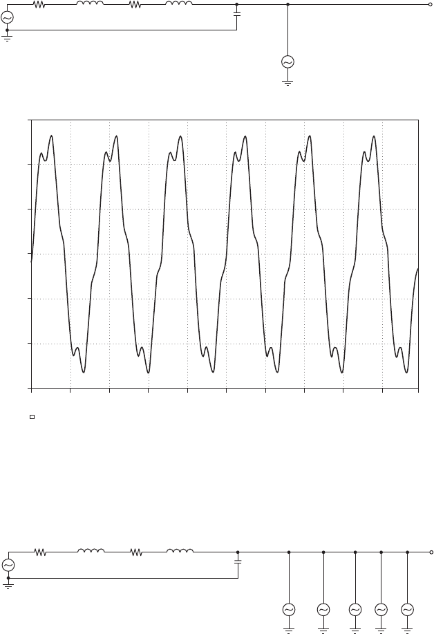
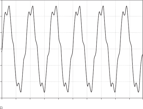
Next, we add a load current that draws a fifth-harmonic current of 50 A
(Figure 4.19). The fifth-harmonic current results in significant load volt-
age distortion.
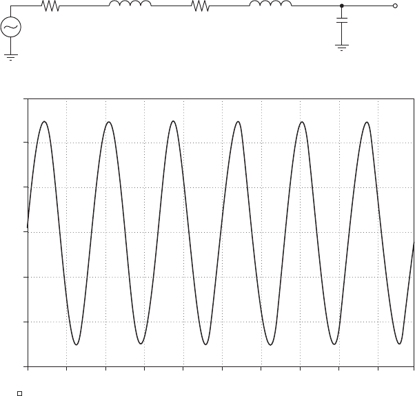
Next, we’ll add a load that has a seventh-harmonic amplitude of
30.0 A, an 11th-harmonic (15.0 A), a 13th-harmonic (7.0 A), and
17th-harmonic (3.0 A). The resultant waveform (Figure 4.20) has
25 percent THD current distortion and 28.5 percent load voltage
distortion. We’ll see in a later chapter how one might add line filters
to improve the load voltage.
60 Chapter Four
Figure 4.20 The circuit for Example 4.5, with 5th, 7th, 11th, 13th, and 17th harmonics.
(a) The circuit. (b) The load voltage.
(a)
V
s
0.000443
R
sys
L
sys
2.81 µH 36.6 µH
Cbank
6900 µF
I
5
V
LOAD
0.0023
R
tr
L
tr
I
7
l
11
l
13
l
17
+
−
+
−
+
−
+
−
+
−
+
−
−600 V
100 ms
110 ms 120 ms 130 ms 140 ms 150 ms
Time
(b)
160 ms 170 ms 180 ms 190 ms 200 ms
0 V
−200 V
−400 V
200 V
400 V
600 V
V(Vline)
(a)
V
s
0.000443
R
sys
L
sys
2.81 µH 36.6 µH
Cbank
6900 µF
I5
V
LOAD
0.0023
R
tr
L
tr
+
−
+
−
Figure 4.19 The circuit for Example 4.5 with fifth-harmonic load current added. (a) The
circuit. (b) The load voltage.
Harmonics and Interharmonics 61
Figure 4.20 (Continued)
−600 V
100 ms
110 ms
V(Vline)
120 ms 130 ms 140 ms 150 ms
Time
(b)
160 ms 170 ms 180 ms 190 ms 200 ms
0 V
−200 V
−400 V
200 V
400 V
600 V
Summary
In this chapter, we developed harmonic analysis tools that will allow us
to analyze waveforms and thus determine harmonic content. Harmonics
cause many detrimental effects in equipment. In later chapters, we’ll dis-
cuss methods of reducing harmonics.
References
[4.1] M. Holland, “Fundamentals on Harmonics,” Proceedings of the 1999 Cement Industry
Technical Conference, IAS/PCA, April 11–15, 1999, pp. 55–67.
[4.2] J. Fourier, The Analytical Theory of Heat (translated by A. Freeman). New York:
Dover Publications, Inc., 1955. First published as Théorie Analytique de la Chaleur,
by Firmin Didot, Paris, 1822.
[4.3] Richard Lee Ozenbaugh, EMI Filter Design, Marcel Dekker, 1996.
[4.4] M. Mardiguian, M., EMI Troubleshooting Techniques, McGraw-Hill, 1999.
[4.5] National Semiconductor, application note AN-990.
[4.6] R. W. Erickson and D. Maksimovic, Fundamentals of Power Electronics, 2nd ed,
Springer, 2001.
This page intentionally left blank

Chapter
5
Harmonic Current Sources
In this chapter, we shall discuss the circuits and magnetics
that create harmonics (multiples of the line frequency) and/or
interharmonics (other high-frequency components).
Harmonics are generated by rectifiers, line-frequency
converters, and nonlinear magnetics. Interharmonics are
created by high-frequency switching power supplies. For most
of what we shall do in this chapter, the fundamental
frequency used will be 60 Hz.
Background
A typical setup that shows how harmonic currents can affect power
quality is shown in Figure 5.1a. An AC voltage source is displayed, with
its associated line reactance, X
s
, and resistance, R
s
. This AC source can
be single-phase or three-phase. The line inductance depends on the
length of the line and the geometry of the conductors. The line resist-
ance, on the other hand, depends on the length of the wire and the wire
gauge used. The AC source voltage then supplies a nonlinear load that
draws harmonic current. Typically, this harmonic source is a rectifier
or other converter.
In Figure 5.1b, we see the single-phase equivalent circuit. Note that
the voltage labeled V
pcc
(for voltage at the point of common coupling or
PCC) has harmonic components due to the harmonic current I
h
drawn
by the load running through the line impedance. If this voltage at the
PCC feeds additional equipment other than the harmonic generating cir-
cuit, the resulting voltage distortion can disrupt operation of the equip-
ment if the harmonic distortion is too high. Harmonic limits are
discussed in great detail in IEEE Std. 519.
In the following, we’ll discuss numerous pieces of equipment that
generate harmonic currents.
63
Copyright © 2007 by The McGraw-Hill Companies, Inc. Click here for terms of use.
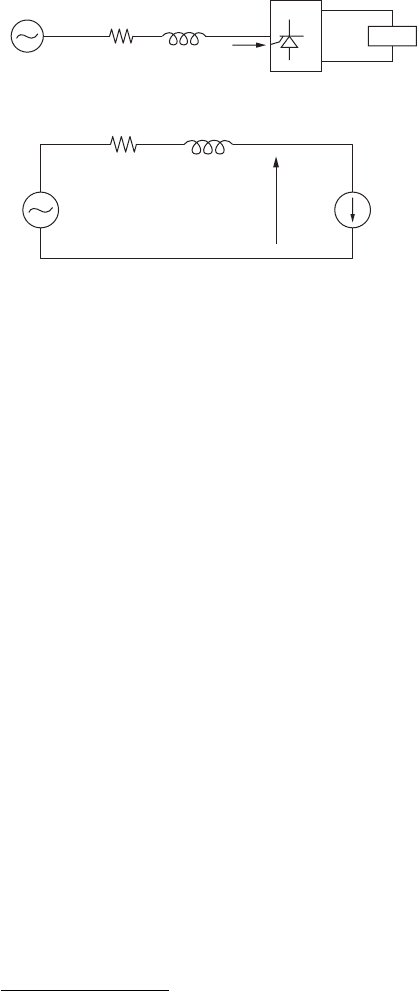
Single-Phase Rectifiers
Rectifiers are used in all sorts of power system and power electronic sub-
systems to convert AC power to DC power. In low-power applications
using single-phase power, rectifiers are used as the front-end of switch-
ing power supplies and small motor drives.
A single-phase, full-wave rectifier with current source load is shown
in Figure 5.2a. This circuit is an idealized model of systems where the
load draws approximately constant current.
1
Figure 5.2b shows the line
current. In this simplified model, the line current is a square wave. In
Figure 5.2c, we see the spectrum of the line current, where the first har-
monic has amplitude 1.0, the third harmonic has amplitude 1/3, the fifth
harmonic has amplitude 1/5, and so on. Note that the line current drawn
by this rectifier circuit is very harmonic-rich, with a THD of 48.3 percent.
Another rectifier is the full-wave rectifier with capacitive filter
(Figure 5.3). In this type of circuit, the diodes are only on for a frac-
tion of a 60 Hz cycle, and the capacitor charges near the peaks of the
input sine wave voltage. Therefore, the line current contains significant
harmonic distortion, as we’ll see in the next example.
Example 5.1: Line-current harmonics. In this example, we’ll examine the
line-current harmonics drawn by the single-phase full-wave rectifier with
64 Chapter Five
I
h
LOAD
AC
source
R
s
jX
s
Harmonic
source
V
PCC
(a)
R
s
v
s
I
h
jX
s
V
PCC
(b)
Figure 5.1 Illustration of a harmonic current source affect-
ing power-quality. (a) A single-line diagram of an AC source
with source impedance R
s
jX
s
and a load that draws har-
monic current I
h
. (b) A single-phase equivalent circuit.
1
For instance, this current source models a series LR load where L/R 1/60.