Raabe J. Hydro power - the design, use, and function of hydromechanical, hydraulic, and electrical еquipment
Подождите немного. Документ загружается.

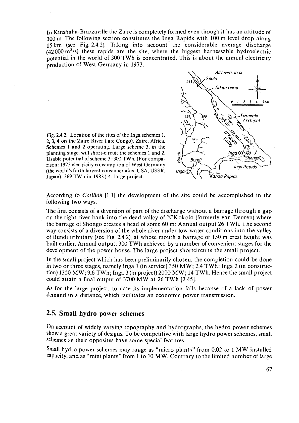
In Kinshaha-Brazzaville the Zaire is completely formed even though
it
has an altitude of
300
nl.
The following section constitutes the Inga Rapids wit11
100
m
level drop along
15 km (see Fig. 2.4.2). Taking into account the considerable average discharge
(42 000
m3/s) these rapids arc the site, where the biggest harnessable hydroelectric
potential in the world of 300 TWh is concentrated. This is about the annual electricity
production of West Germany in 1973.
Fig.
2.4.2.
Location of the sites of the Inga schemes
1,
2,
3,
4
on the Zaire
River
(late Congo), Zaire, Africa.
Schemes
1
and
2
operating. Large scheme 3, in the
planning stage, will short-circuit the
schemes
1
and
2.
Usable potential of scheme
3
:
300 TWh. (For compa-
rison: 1973 electricity consumption of West Germany
(the world's forth largest consumer after USA, USSR,
Japan): 369
TWh in 1983.)
4:
large project.
According to
Cotillon
[1.1] the development of the site could be accomplished in the
following two ways.
The first consists of a diversion of part of
the discharge without a barrage through a gap
on the right river bank into the dead valley of
N'Kokolo (formerly van Deuren) where
the barrage of Shongo creates a head of some 60
m:
Annual output 26 TIVh. The second
way consists of a diversion of the whole river under low water conditions
into the valley
of Bundi tributary (see Fig.
2.4.2), at whose mouth a barrage of 150 m crest height was
built earlier. Annual output: 300
TWh achieved by a number of convenient stages for the
development of the power house. The large project shortcircuits the small project.
In
the small project which has been preliminarily chosen, the completion could be done
in
two or three stages, namely Inga 1 (in service)
350
MW;
2,4
TWh; Inga
2
(in construc-
tion) 1350 MW;
9,6
TWh; Inga
3
(in project) 2000
MW;
14 TWh. Hence the small project
could attain a final output of 3700 MW at 26
TWh [2.45].
As for the large project, to date its implementation fails because of a lack of power
demand in a distance, which facilitates an economic power
transn~ission.
2.5.
Small
hydro
power
schemes
On
account of widely varying topography and hydrographs, the hydro power schemes
show a great variety of designs. To be competitive with large hydro power schemes, small
schemes as their opposites have some special features.
Small hydro power schemes may
range as "micro plants" from 0,02 to 1 MW installed
capacity, and as "mini plants" from 1 to 10 MW. Contrary to the limited number of large

plants, small hydro pol,ver schemes exist
in
grc:it riun~ber. Sonlctir~les they are the first
step in
using
a
site of larger hnrrlessnbie potential; see
[1.34
to
1.421.
Most small pl;ints mainly of "niicro power" type arc located in rerliote areas of the Third
World with
a
Ion popul:ltion tlcnsity, usuaily near to a smaller township with
a
grid, or
near to a
villngc without any electrificalion. In the first case, the consumer may be a
factory or a hospital
etc., in the second case the village itself. I11 both cases no
essential
and long electric transmission line has to be installed, which favours the economical feasi-
bility of
thc plant. When the sni:~ll plant is connected with ;in existing relritivcly larger
AC
grid the speed cofitrol can be omitted. In the absence of a larger grid tne small plant
u
s~pplics a grid by itself. Then some speed control becomes necessary.
In countries with
;\
large usable potential not yet harnessed, small hydro power plants
may be erected first on the more
econon~ical sites. In countries with largely exploited
hydro potential, the small hydro power plants usually are using the less economical small
rivers with
thcir strongly varying duration line.
In
thc case of economically feasible sites with falls, rapids or great slopes of the river, the
latter is usually
by-passed
through a simple diversion, or
a
simple run-of-river scheme as
possibly rapids
tarbines (Cap.
10.2).
On
a
snlall river with irregular supply and a flood
flow relatively high compared with the rated flow of the plant, again
a
simple diversion
should
he
applied. Any diversion has the economical advantagc that
it
saves tlie cost of
barrage and
spill\l;ay at net head and also the cost of dams along the river itself. Thus the
civil engineering works, which normally account for two third to one half of the total
initial
COF~,
may
be considcraSly reduced.
Intakes are
the Achilles heel of small hydro power schemes and their design is of crucial
importance.
Fcr very srriall intakes of about
0,5
m3/s, a skip design has been developed,
w!izre \+ate; and
sediments
jump right over the intake during flood flow. Combined with
a riprap-lined stilling basin, this device has developed
i~to cheap and effsctive intakes for
mai~tenance-free
operation.
,4t any rate sedimentation in the i~tnke channel has to be
preven~ed.
Usl:ally
the intake has
a
screen and a stop log, which at low head may save
the
iiistallari~n of any gate
or
valve before the turbine inlct.
There is a con:inuol~s debatz o-der the merits of maintenance-free versus ease-of-main-
tenance for small
hydro
equipment. The first reduces the labour requirements and the
servicing
cost: the second requires personal visits and then reduces the possibilities of
break
do\vns through lack of regular visual inspection. The second should be preferred
whzn skilled labour is readily available in the supporting community, but the first has
many advantages
when b~~ilding small schemes in underdeveloped countries, neigh-
bouring the region in which the plant is manufactured.
The usual
iow
head and the low installed capacity of small hydro power schemes make
their specific
investment cost/installed kW extremely high. Therefore the initial costs of
the schcme's components have to be reduced.
They
are the cost of:
1)
transmission line,
2)
civil en~ineering works,
3)
speed governor and other control devices,
4)
power house,
5)
accessories of each sets such as main, vdve, device for starting, syilchronizing, shut
down, limiting overspeed etc.,
6)
generator,
7)
turbine.

The absence of a transmission line, a simple diversion or run-of-river design, and the
of any submergence meet the requirements of both the first cost terms.
The elimination of conventional turbine speed governor, not only because the governor
of
small machines is itself an expensive constructional mcn~bcr, but
31~0
its removal.
permits further simplifications to the turbine (removal of gutc, needle or runner blade
adjustment equipment), particularly when high efficiency is not a dominant concern.
The conventional speed governor may be eliminated if the turbine is operated. e.g. at
constant flow and constant load. To achieve this also when the machine supplies a srid
by itself, some designs have used hydraulic or eddy current brakes. But recently,
a
stron?
interest has been in the control of speed by rapid adjustment of electrical load. This can
be done,
e-g. by switching frequency-controlled separate dummy resistors across the
alternator terminals. The encrgy dissipated may be used to heat nrater or to produce
hydrogen by electrolysis.
In
plants connected to a larger AC grid, the speed is retained
by the magnetic force between the armature and the rotary field of its stator. Here the
load can be set at will by means of an opening limiter (Cap. 11.2).
In a not too cold and rainy climate,
the cost 4) of the power house may be considerably
reduced by locating the whole set or its generator (S-tube turbines or bulb turbines
Ivith
bevel gear) in the open air, there possibly protected by a box or a dry shelter.
The cost
5)
of accessories for each set can be reduced by
install in^
one generating unit.
This is only compatible with varying demand if the turbine has a flat curve of
efficiency
versus its load, as for example with multi-cell cross flow turbines of the
-1lichell-Ossberger
type, inclined-jet impulse turbines of the "Turgo" type, ordinary impulse turbines or any
kind of action turbine, and double, or runner-blade-adjusted reaction turbines (usually
axial turbines); but both the latter are rather expensive.
If
efficiency is no dominant concern, e.g. when the plant uses a river with a wealth of
hydro potential, then the multi-cell cross flow or the inclined-jet impulse turbine should
be preferred for their simplicity (cylindrical plates as rotor
vanes).
The cost
6)
of the generator can be substantially reduced by a simple step up spur gear
or a less simple bevel gear (bulb turbine). This is usually possible in
lo\\, and medium head
plants. It may be remembered (Cap. 10.5) that any gear can be converted into an
o\.er-
speed protection of the generator (which also makes the generator cheaper) by means of
a
speed-operated clutch between the gear casing and its base.
The major characteristics of a cheap direct coupled small generator are:
a) In vertical sets, the axial thrust is carried
by
a generator bearing.
b)
The
set has a greater propensity to overspeed. In the predominant low head range the
rotary parts may be not overstressed during runaway. Here runaway map correspond
more to an idling of the set. This holds especially for very small low head units where
countermeasures against runaway, after an alarm signal, occasionally are released by
hand
operation of the inspection personal.
c)
The generator requires an extra inertia usually in form of a separate
fly
wheel
to
reduce
Ovcrveed at sudden load rejection.
d)
Cooling is effected by means of air from outdoors. Moreover roller bearings prevail
in
the smallest units.
Wllen (be output is below
6
MW,
the exciter can be saved by applying an induction
(as~nchr011ous) generator. This requires reactance compensation from extra capacity in
assofi:lted synchronous machine$ or from1 special capacitors if the set supplies a grid by
ilsclf
(50
c;lllcd isolated operation).

The
cost to the matiuf:icturcr of skillcd labour at fiir distant sites can
bc
rcduccd
consickr.ably or climini~tcil
if
turbine :\lid generator ilrc rtiour~tcd on
;I
coninion b;tsc ylxte
in
thc m:~nuLicturcr's fllctory. 'This is an casy
procedure
for sninll sets with
a
horizontnl
shaft cquipped with cross flow or irnpulsc
turbines,
sec 1:igs.
3.4.9
and
10.
To reduce the cost
7)
of the turbine, a
simplified
design should be preferred, e.g. flow
admissior? through
ra.
pit
itat
the end of a flume, removal
of
any adjusting
mechanism,
low
number of stay and guide vanes, linkage for gate adjusting mechanism in water, self
or
water lubricated bearings of shaft and trunnions, roller
bearings,
conical hub or plane
disk hub, cylindrical shroud, removal of shroud, cylindrical forms for vanes and buckets,
avoidance of any
submcrgence. Such a design Inay lcnd itself to largc volumc production
at low unit cost, or
it
may be manufactured in
a
Third World workshop using local labour
and readily available materials.
According to
Racl~mcin~l
[2.50]
standardization is justified
in
the output range from
O,1
to
2
MW and
for heads from
2
to
800
m.
Reducing
this
only to the geometry of the turbine,
the
runner diameter should be tailored to the working data
of
the site, especially
ir,
countries with scarce energy resources.
3.
Survey
and classification
of
essential devices
of
a
hydro power plant
-
3.1.
Introduction
and survey
The various machines and devices, which are found in hydro power plants can be
imagined to exist
in
a river diversion power plant. This simplifies the introduction of all
the possible structural members, their variety, their purposes, their falling out of
nse and
eventual omissions. For example, in the case of a run-of-river power plant the diversion
section is reduced to the turbine.
Fig.
3.1.1
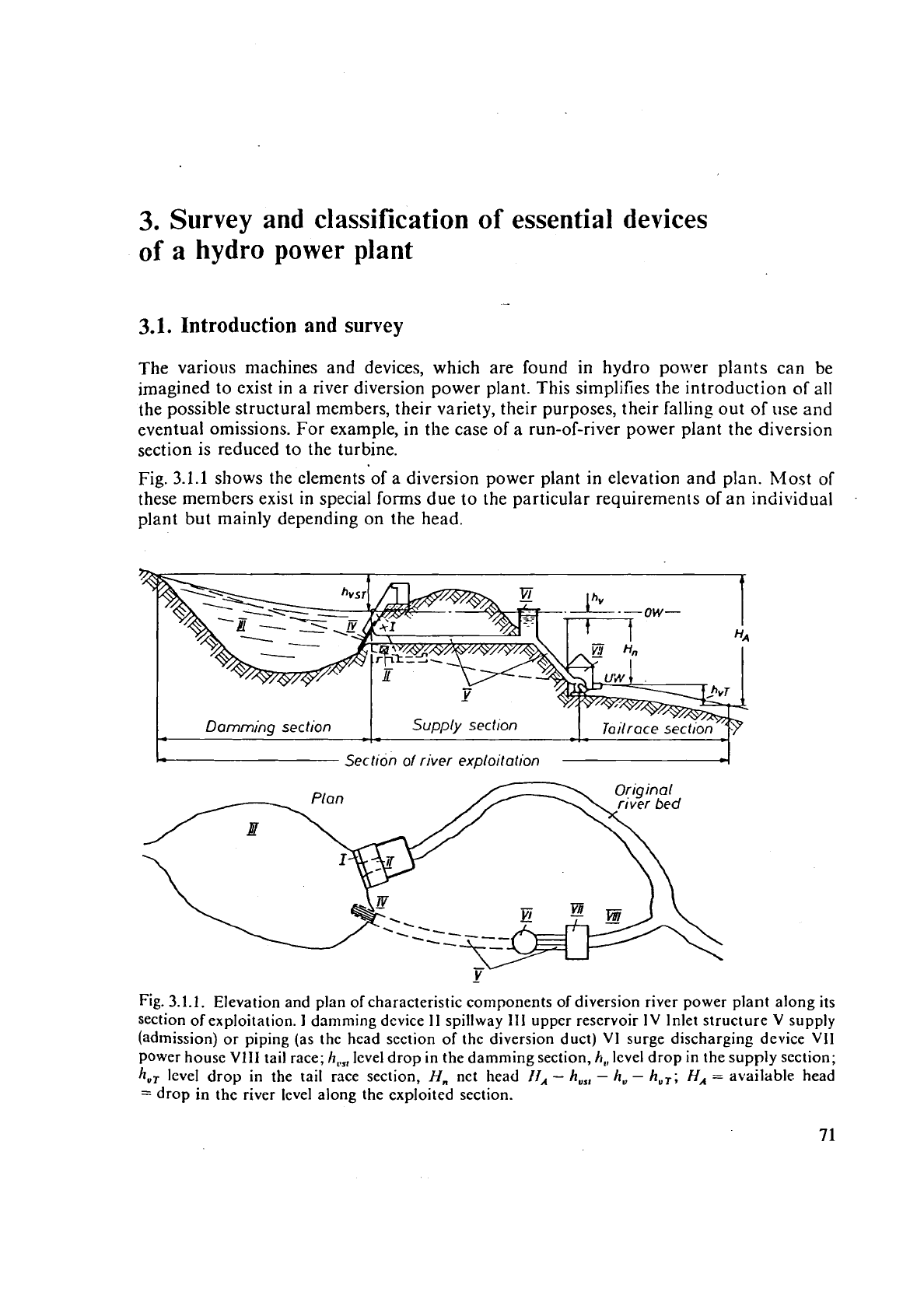
shows the elements of a diversion power plant in elevation and plan. Most of
these members exist in special forms due to the particular requirements of an individual
plant but mainly depending on the head.
Fig.
3.1.1.
Elevation and plan of characteristic components of diversion river power plant along its
section of exploitation.
I
damming device
I1
spillway 111 upper reservoir 1V Inlet structure
V
supply
(admission) or piping (as the head section of the diversion duct)
V1 surge discharging device VII
Power house VIII tail race;
h,,,
level drop in the damming section,
h,,
level drop in the supply section;
h,,
level drop in the tail race section,
H,
net head
Ii,
-
h,,,
-
h,
-
h,,;
HA
=
available head
=
drop in the river level along the exploited section.
-
The d;~mniing devic:e
I
blocks thc dotvn:;!re;ini cnd of tlic tipper bilsi11 (rcscrvoir).
In
storage plant5 for heads abovc about
30
rn
it
consists or
a
barriige \isu;illy ;issistcd by
dikes.
In
i\
run-of-river plant
~vitli
lieads I~clow
30
rn
the power house and weir, assisted
b) Ions dikes along the rivcr banks, repl;icc
the
barriige. In diversion pliints this clevice
is rcducecl to
a
tvcir,
in
channel plants
ii
cansists of dikes power house
and
weir.
-
The spillwi~y or flood discharging dcvicc
I1
firstly controls the mrtximnrii
permissible
head watcr lwel by mealis of barragc crcst, fixed or adjustable weirs with movable or
rotary gates,
by syphons or by-pass outlcts. Secondly
it
l~irist enable thc passagc of high
watcr which could be catastrophic.
In the
CitSC
of a run-of-river and barrage power plant the spillage occurs under the plant's
head.
In
tliversic~n plants the head at spillway is smaller and hence also the
bad
effects of
spillag~
to
be
controlled. For the controlled dissipation of spilled discharge
a
stilling basin
at
tlie foot of spi!livay is used. The lattcr call be omitted
ill
the case of a ski jump spillway.
-
The fish protecting device
(if
a
fishery act exists) consists of an inlet screen at least at
the intake of machines
bat
if
possible also before weirs with a width small enough to
przvent the passage of finger-thick young fishes. Otherwise a large n~ortality rate occurs,
caused by shock or cavitation damage. to the fish. This ranges up to 80% at a head of
100
m
[3.1:
3.21.
In rivers with species such as salrnon and sturgeon, which migrate at
spawning time,
a
tish pass must be provided with cases according to the length of fish (e.g.
the "Beluga" of the Volga (Accipenser huso) reaches
9
m in length).
-The unpcr basin (reservoir) 111 is formed
by
the damming device. If needed especially in
divcrsio~i plants, the bzisin contains a sand separator. This cares for sedimentation of silt
by
flon I-c~ardation and turbidity artificially created upstream of the intake structure.
--
Thc ir:tnkc structure
1';
for the working fluid is always underneath the lowest head
txatei levcl, protected
by
a screen and usually cleaned by a trash rack [3.3].
Care
must be
taken that the inlet
is
frec
of
vortices [3.4]. In run-of-river plants the inlet is in front of
tllz potver house. In high
hex!
plants
it
may be within the barrage or a separate structural
member,
sometimes in a totver within the reservoir. In diversion plants the sedimentation
of
silt
may
be
eased. according to
i\/losorl)v'
13.51,
if
the structure lies on the hollow side
of
tire
flow
caused
by
the spillage.
--
T!I~
supply (piping)
V
runs from the intake structure to the turbines. 111 the case of a
higli head diversior? plant this device ccnsists
iil
the upper
reach
between intake and surge
tank
(ivhen
it
exists) of a tunnel or a tun~eled or open channel of small slope. 111 the latter
case
tl:c surge tank
is
replaced by a swell weir. In the downstream reach, the so called
"poivcr drop", the i~attr
is
conveyed to ihe power house either underground by
a
pressure
shaft or outdoor by a penstock
[3.6;
3.71. In front of the power house the main may form
branches to the individual machines
[3.8]. In a barrage river plant the supply crosses the
dam (barrage).
In
a
low head plant, the supply consists either of a longer channel (channel power plant)
or
it
shrinks to the bell mouth
of
the turbine's intake.
-
The surge relievins device VI is provided in the supply
V,
the hydraulic machine or the
tail water tunnel. It should lessen the surges of pressure or water level induced by the
regulation of
the machine at least in the longer ducts. For high head plants it usually
consists
of
a
surge tank between the upper and-downstream reach of supply (sce Fig.
3.l.i)
[3.9
:o
3-15].
-.
Undereround power stations with a vertical or steeply inclined and hence short supply
with
heads up to 600
m
may omit the surge tank upstream of the machine. This usually
requires
a
surge tank at the inlet of the tail water tunnel which is then very long
[3.16].
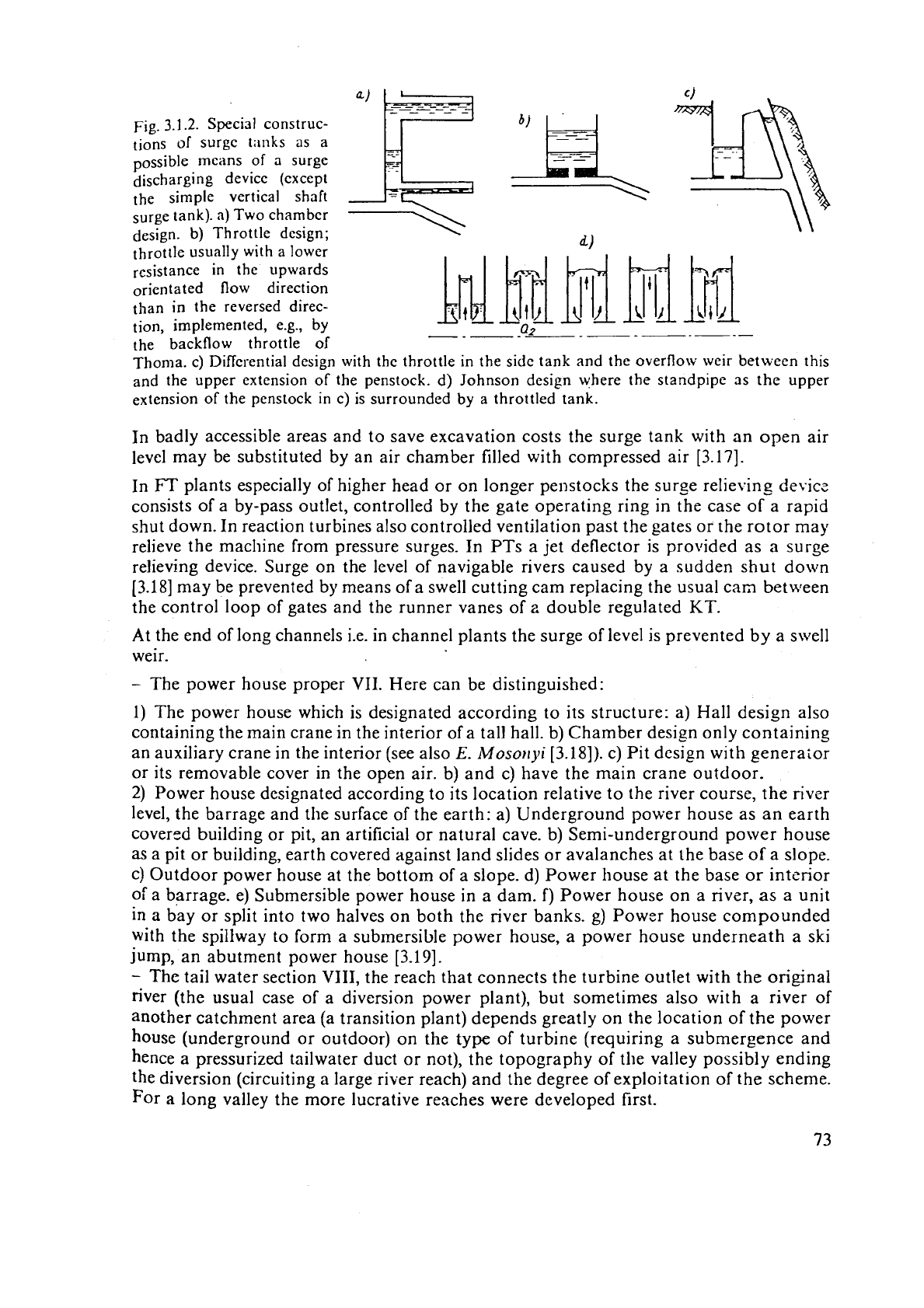
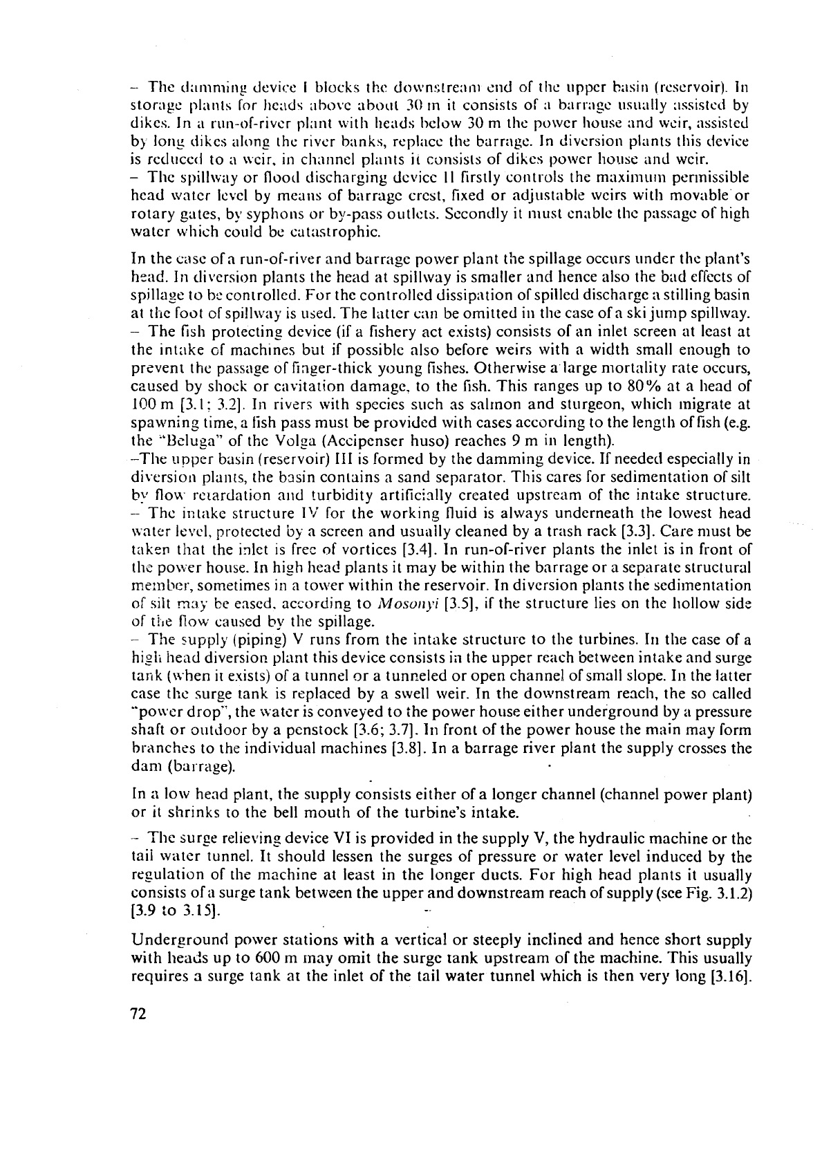
Fig.
3.1.2.
Special construc-
[ions
of
surge tiinks as a
possible means of
a
surge
discharging device (except
the simple vertical shaft
surge tank).
a)
Two chamber
design. b) Throttle design;
throttle usually with a lower
resistance
in the upwards
orientated flow direction
than in the reversed direc-
tion, implemented,
e.g.,
by
-.
-
-
-
-
-
-
-
-
-
-
-
the backflow throttle
of
Thoma. c) Differential design with the throttle
in
the side tank and the overflow weir between this
and the upper extension of the penstock. d) Johnson design where the standpipe as
the
upper
extension of the penstock in c) is surrounded by a throttled tank.
In badly accessible areas and to save excavation costs the surge tank with an open air
level may be substituted by an air chamber filled with compressed air
[3.17].
In
FT
plants especially of higher head or on longer penstocks the surge relieving
device
consists of a by-pass outlet, controlled by the gate operating ring in the case of a rapid
shut down. In reaction turbines also controlled ventilation past the gates or the rotor may
relieve the
maclline from pressure surges. In PTs a jet deflector is provided as a surge
relieving device. Surge on the level of navigable rivers caused by a sudden shut down
[3.18] may be prevented by means of a swell cutting cam replacing the usual cam between
the control loop of gates and the runner vanes of
z
double regulated
KT.
At the end of long channels i.e. in channel plants the surge of level
is
prevented by a swell
weir.
-
The power house proper VII. Here can be distinguished:
1) The power house which is designated according to its structure: a) Hall design also
containing the main crane in the interior of a tall hall. b) Chamber design only containing
an auxiliary crane in the interior (see also
E.
~Moso~~j~i
[3.18]). c) Pit design with generaLor
or its removable cover in the open air. b) and c) have the main crane outdoor.
2)
Power house designated according to its location relative to the river course, the river
level, the barrage and the surface of the earth: a) Underground power house as an earth
covered building or pit, an artificial or natural cave. b) Semi-underground power house
as
a pit or building, earth covered against land slides or avalanches at the base of a slope.
c) Outdoor power house at the bottom of a slope. d) Power house at the base or interior
of a barrage. e) Submersible power house in a dam. f) Power house on a river, as a unit
in a bay or split into two halves on both the river banks. g) Power house compounded
with the spillway to form a submersible power house, a power house underneath a ski
jump, an abutment power house
[3.19].
-
The
tail water section VIII, the reach that connects the turbine outlet with the original
river (the usual case of a diversion power plant), but sometimes also with a river of
another catchment area (a transition plant) depends greatly on the location of the power
house (underground or outdoor) on the type of turbine (requiring a submergence and
hence
a
pressurized tailwater duct or not), the topography of the valley possibly ending
the diversion (circuiting a large river reach) and the degree of exploitation of the scheme.
For
a long valley the more lucrative reaches were developed first.
F-or
;I
I-1111-of-ri~cr
plani
\vil
I1
;I
powcr housc
ill
a
bay this scctiorl bcco~nes as long
;IS
the
spillw:iy ;tbutmcr~t
tlia
r
I,tjrclcl-s
upon
thc pnulcr lior~sc. For
a
bnrragc plant on a river
it
sllririks
to
Lcro
3.2.
Dams
3.2.1.
Classitication
of
dams
The denomination "dam" includes here only fixed clamming devices excluding a power
house and
spillwav used as a damnling device in run-of-river power plants. Dams create
a constant obstacle to the river whereas weir gates
permit a varying level obstruction
allowing therefore
regi11a:ion of head water Icvel. With the first device
a
large reservoir
is
made, lvhereas with the second, whose height rarely exceeds
30
nl,
only
a
daily cr
weekly rescrve ~vould be made.
A
darn or a barraze consists of
a)
a
solid or hollo\v bady of masonry, concrete, earth- or rock-filled, made water tight,
b) a crest carrying usually
a
road,
C)
a
foundation on the river bcd and a support on the slopes of its valley. Usually either
on
the crest or in the concrete part of the body. therc is a spillway.
Dams are classified
rlccording to the principle of resistance against hydraulic thrust as
I)
Gravity dam fdesisnated as dike or embankment when earth- or rock-filled)
11)
Arch
darn
Lvith 5in~le or double curvature
111)
hlultiple arch dam will1 buttresses as supports
I\')
Mixed dams consisting of
a
mixture of the types previously mentioned
V)
Zlollow dams
\iith
reinforced flat or arched decks of concrete as external walls,
supported by
butt:ssscs partly filling the dam section.-
Thc crest height of tl,e dam: This is given
by
the depth of the valley. It should be as high
as possible to catch the largest possible
volume of water due to the catchment area and
with respect to the fact that any subsequent increase of height is extremely difficult and
expensive. For this purpose an
zdequate site (if there is one) has to be selected.
3.2.2.
The
foundation
of
a
dam
and related problems
The foundation of
a
dam includes not only that part on the bottom of the valley but also
the part on the valley slope. The foundation type depends mainly on the quality of soil.
It
has to transmit the hydraulic thrust of the barrage and the loads related to
it
from the
base
of
the dam into the adjacent soil. takincg care that this is not overloaded with respect
to its
pern~issible pressure, cormal tensile stress and shear stress to avoid slippage
[3.20]
arid landslide
[Xi].
Sail and dam are also stressed by seepage-induced uplift.
Xloreover thc ground should be as tight as possible against seepage
[3.22].
If possible
a
dam should
basc on rocky ground.
111
some sites, e.g. that of the
Aswan
high
dam (3.231
the ground is formed
hy
3
sand dcposit
more
than
100
m underneath the river bed.
In
thesc cases one has to be satisfied
with the
itljection of
3
grout curtain through pipes dowri to the upper face of the rock or by
compressing the ground in
the best possible way to avoid undermining the dam foundation.
To
prevent scepagc. biankcts
[3.24]
and other means are used
[3.25].
Diirins the filling
of
a rescrkoir the danger of slippage of the slopes of valley is increased.
In
valleys
with a steep slope. a
slippngr: of soil there, originated by the basin being filled too fast, may cause
by displacement of watcr in the roscrvoir,
a
surge of level, o\e:topping the dani crest \\.it11 possible
terrible consequences. The most spectaci~lar accidcnt induced in this way by
landslide
occured
st
the
Vajorit dam in Northern Italy with about
2000
casualitics
(3.261.
Other severe accidents occured as a consequence of slippage of soil in the abutmcnt of the darn aud
the valley slope resulting in a barrage bursting. In this
way
the dam of Malpnssct Frejus in France
was damaged destroying the village downstream of the dan~ site
[3.27].
To prcdict a dam failure, thc body of the dam and its foundation
are
equipped with inspection
to control the
seepage and to control displacenlent and strain by continuously gausing
them. They are also used for drainage (Fig.
2.3.4) [3.28
to
3.321.
~t seems advisable to inform the population threatened by a dam failure in advance that in the case
of emergency a certain signal would be given to them urging them to flee to
T,
station suficisntly
elevated above the valley ground, as to be out of the reach of a possible flood wave. Naturally such
a point has to be provided.
However, the problem exists how to set the point
at
which
an
alarm should be made. A sig11aI ivhich
was too early and hcnce too often would lose its credibility. Lifting the threshold of tripping too
much, could be too late to prevent a disaster. According to
cxpericnces, mentior,cd by
Farlelli
[3.33.
3.341
dams may undergo without any danger large gradual deformation, much highcr than that fised
before as the disaster limit. There remains the problem how to relate the above measurement to thz
tripping of alarm.
Latest experience with dams, e.g. Aswan dam in Egypt, located in regions origin
a
11.-
t
not
effected by earthquakes, demonstrate that such events may be caused by
lifting and
lowering the level of a reservoir. This seismic activity can be traced to inactive faults in
the relatively thin
SiAl crust of the earth (Si from SiO,
=
quartz and A1 from A1-0,
=
pure clay as the essential component parts of it)
[3.35; 3.361.
Hence forced vibrations
are also used to test dams
[3.37].
It seems likely that the effect of added forces by the weight of water in the reservoir liberates greater
tensions in this crust. It also appears in this context that the crest height of the dam is more
important than the volume stored. This seismic activity becomes pronounced once the
he:ght
exceeds
100
m. Here are the crest heights of some earthquake, landslide affected dams: Nurek
317
m,
Vajont
262
m,
Hoover
226
m, Contra
220
m, Canelles
150
m, Kremasta
147
rn, Monteynard
130
m,
Cariba
130
m, Pieve de Cadore
112
m, Aswan
1
1
1
m, Konya
103
m,
i3.38
to
3.4
11.
The Konya disaster of
1967,
in the Indian Peninsula which resulted in a heavy loss of lives and
considerable property damage, was due to an earthquake whose epicentre coincided with the dam
itself
(3.421.
Hence stability control is required
13.431.
Insurance against dam risks is discussed
13.441.
The crest height of the highest dams is listed in Table
3.2.1.
3.2.3.
Gravity
dams
Gravity dams may exist as masonry, concrete, rockfilled or earthfilled dams. The gravity
dam is a barrage which resists the hydraulic thrust by its own weight with respect to its
moment about the tilting edge on the downstream heel of
the dam and with respect to
its friction on the ground.
A
slight curvature
of
the dam in its plan convex to the reservoir,
sometimes found in masonry dams, balances a part of the thrust
by
internal wall pressure
instead of friction.
An embankment is made of stones, gravel and sand, consisting in its core
of
concrete,
earth and clay or loam against seepage with an asphalt coating against water action on
its water facing side.
A
dam of concrete is usually erected at first in separate blocks to
avoid internal stresses due to the release of the heat of combination and the subsequent
thermal
expansion of concrete
13-45
to
3-47].

Tnble
3.2.1.
Crest
hcight
of
d:ms
I~ighcr
than
200
m.
Namc Country
TY
PC
crcst hcight
(in
ni)
Nurck
Grand Dixcnce
lnguri
Vajont
Mica
Sayano
Sushcnsk
Maavoisin
Oroviile
Chirkey
Bakkra
Hoover (Boulder)
hlratinje
Contra
Dworshak
Glen Canyon
Tokiogul
Danicl Johnson
Auburn
Luzzone
Keban
31ohamed
Reza
Chan Pahlevi
Alrnrndra
Rezs Chan Kabir
Kol brein
USSR
Suisse
USSR
Italy
Canada
USSR
Switzerland
USA
USSR
India
USA
Yugoslavia
Suisse
USA
USA
USSR
Canada
USA
S\vitzerland
Turkey
Iran
Spain
Iran
Austria
Rvchfill dam
Gravity dam, concr.
Arch dam
Arch
dam
Hockfill dam
Arch
d;lm
Arch tiam
Earth dam
Arch dam
Gravity dam,
conc;.
Arch darn
Arch darn
Arch dam
Gravity darn, concr.
Arch
dam
Arch
dam
I\.lultiple arch
Jam
Arch dam
Arch dam
Rockfill dam
Arch
dam
Arch dam
Arch dam
Arch dam
The problem whether
a
zrauity dam is built of masonry
or
concrete or as an embankment
of
grasrzl.
clay
etc., depends on the one hand on the material found
in
the neighbourhood
2nd
the
tra11sport;ition
fiicilities
for cezent. On the other hand
it
depends on the reli-
ability
and
e~istenoe
of
a
rocky ground, that
is
needed for
a
concrete dam, and the dam
volume
(3.481.
If
there
is
locally no material for making it watertight such as clay or loam, then concrete
is used to build
t5e
dam.
or masonry
af
hewn rock fwnd in the ncighbourhood
of
the
site. In
seneral
a
dam
of
concrete or masonry rleeds
a
reliable rocky foundation.
An
embatikment is preferred for smaller crest heights or where it
is
built on deep sandy soil
(see
Aswan
darn, Fig.
3.2.1 13-23]).
In regions of greater earthquake probability
a
concrete dam is preferred. Nevertheless the
world's
highest dam in the hrurek power plant, Tadschikistan, USSR, being
in
such
an
endangered resion, is an embankment
j2.171.
Occasioi~ally
a
sravity
dam
of concrete is
continued
at
both
its
ends
as
an embankment.
In
the
case
of
exclusively
rocky
soil
at
the
site c.f
dam,
the gravel needed has to
be
quarried (Itaipu
[2.28]).
With the following list of symbols:
H,.=
crsst height,
b
=
wall thickness at mot,
1,
=
crest length,
the
characteristic dimensions of some iinportant gravity dams are: Nurck, Tadschikistan. IJSSR.
H,
L=
31
7
m,
b
=
I
ZOC,
rn:
Hoover (Boulder), Colorado
r
iver,
USA.
H,
-
226
m,
b
=
170
m,
I,
=
395
In;
Grad Coulee, Columbia River, USA,
H,
=
168
m,
6
=
90
m,
1,
=
1592
m;
Grand
Dixence, Oixcnce river, Switzerland,
No
=
285
m,
b
=
200
m,
I,
=
750 nl (Fig. 3.2.2)
[3.49
to
3-52:.