Pumping Station Desing - Second Edition by Robert L. Sanks, George Tchobahoglous, Garr M. Jones
Подождите немного. Документ загружается.

passages adds mass directly;
(2) the fluid
displaced
by
the
presence
of the
impellers
and
shaft
adds
its
mass because,
as the
rotor vibrates within
the fluid,
it
must displace this mass;
and (3) the fluid in
close
clearances must accelerate
off to the
sides much
faster
than
the
rotor vibration acceleration
to
make
room
for the
rotor motion. Item
(3)
can, potentially,
add
mass many times
its
displaced
mass.
•
Lomakin
effect
is an
unexpected support force that
occurs
in
pumps
at
annular seals such
as
wear rings
due to the
action
of
Bernoulli's
effect
during
the
normal leakage process. This
effect,
discussed
in
detail
by
Black
[21]
and
Marscher [22],
can
change
the
rotor support
stiffness
dramatically
and
hence
the
rotor natural frequencies.
The
effect
thereby
either avoids
or
induces possible resonance between
strong forcing frequencies
at 1 and 2
times
the
run-
ning
speed
and at one of the
lower natural
frequen-
cies. Although
the
effect
is
usually beneficial,
it
strongly depends
on the
annular seal diametral
clearance,
and
loss
of
this clearance
due to
erosion
and
wear
in
service
can
lead
to
loss
of
Lomakin
effect
and the
appearance
of a
resonance problem
where there
was
none before.
Vibration Measuring
Equipment
Modern vibration test equipment
can be
divided into
three levels
of
detail
and
sophistication:
•
Hand-held
sensor/meter
packages.
The
advantages
of
this equipment
are
that
it is
easily portable, easy
to
use, inexpensive,
and the
sensor
is
relatively
lightweight
and
rugged.
The
disadvantages
are (1)
the
frequency
information
it
provides
is not
very
distinct;
(2) it is
difficult
to
distinguish hydraulic
forces
and
mechanical resonances
from
excitation
harmonics
of
multiples
of
running speed caused
by
imbalance
and
misalignment;
(3)
only
one
probe
at
a
time
can be
used,
so the
powerful
modal testing
discussed
by
Marscher [18] cannot
be
performed;
and
(4) the
velocity probes used
in
these units rap-
idly lose accuracy outside
of the
range
10 to 17 Hz.
•
Single-channel
FFT or
real
time analyzers. These
devices
are
rather complicated
and
best used
by
experts. Velocity probes
can be
used with them,
but
accelerometers
are
better because they
(1)
have
a
broader accurate range
of
frequency
(2 to
17,000
Hz)
and (2) are
robust.
FFTs
may
also take input
from
eddy current
shaft
proximity probes that sense
the
displacement
of a
rotating
shaft
relative
to
some
stationary point
on the
pump housing.
The
advan-
tages
of the
single-channel
FFT are (1) it is
moder-
ate in
cost;
(2) it
gives accurate plots
of
running
vibrations versus frequency (thereby allowing
the
broader
frequency
range taken
up by
resonances
and
hydraulic forces
to be
detected
relative
to the
narrow frequency range vibration response
of
mechanical forcing frequencies);
and (3) it
provides
enough frequency resolution
to
distinguish subtle
but
important
frequency
differences
between reso-
nances,
hydraulic forces,
and
mechanical
forces.
An
important disadvantage
of
single-channel
FFTs
is
that
experimental model analysis (EMA) testing
and
recording
of
shaft
position versus time
"orbits"
cannot
be
obtained. Another disadvantage
is
that
the
timing
relationship
or
frequency correlation
between pressure pulsations
or
vibrations
in a
pos-
sible
"problem
source" area
and
vibrations
in the
problem "symptom
area"
cannot
be
obtained. These
procedures
often
play
an
important role
in
vibration
problem solving.
•
Multi-channel
FFT or
real
time analyzers.
As
with
single channel
FFTs,
these
are
also based
on the
fast
Fourier transform. They
are
heavier
(7 to 36 kg or 15
to
80
Ib)
and
cost more than single-channel units,
but
they allow measurements
in two or
more chan-
nels
at
once,
so
that
the
EMA, orbit,
and
correlation
measurements mentioned above
can be
performed.
As
with single-channel
FFTs,
any
type
of
voltage-
output
transducer
can be
used, including velocity
probes.
The
more accurate accelerometers
and
dis-
placement proximity probes are, however, preferred.
Data
Types
and
Formats
Vibration test data
are
usually plotted
in
three
differ-
ent
forms:
• A
Cartesian plot
of
vibration amplitude versus fre-
quency ("signature
plot"
or
"spectrum").
Some-
times this plot
may be
combined with
a
plot
of the
phase angle (the "lag
angle"
from
application
of the
exciting force
to the
responding vibratory motion)
versus frequency.
It is
then called
a
"Bode
plot."
• A
Cartesian plot
of
vibration amplitude versus time,
similar
to a
typical oscilloscope trace
("time"
plot).
• A
polar plot
of
vibration versus time
in a
plane per-
pendicular
to the
shaft
axis
(an
"orbit").
The
amplitude scales
may be
linear
or dB
(base
10
logarithm).
A dB
scale
is
often
used
to
improve
the
resolution
of
natural
frequency
peaks.
The
amplitude
scale generally represents
rms
(root mean square) val-
ues
unless specifically
scaled
otherwise.
To
convert
rms
values
at a
specific
frequency
to
peak
to
peak,
multiply
by
2.83,
and to
convert
from
peak
to
peak
to
zero
to
peak, divide
by 2.
22-4. Introduction
to
Vibration
and
Noise
Calculations
The
goals
of the
following
1
1
sections
are to
provide
for
a
deeper understanding
and
appreciation
of
vibra-
tion,
to
present means
for
evaluating
a
particular situa-
tion,
and to
offer
suggestions
for
reducing vibration
or
noise
to an
acceptable level.
The
calculation procedures presented here
are
generally
simplified
expressions that
are
meant
only
to
give
an
idea
of the
severity
of
a
given
situation.
If
accurate predictions
of
noise
and
vibration levels
are
required,
a
qualified
specialist should
be
con-
sulted.
It may not be
easy
to find
qualified special-
ists,
but a
good place
to
start
may be
either
the
National Council
of
Acoustical Consultants,
the
Institute
of
Noise Control Engineers,
or the
Vibration
Institute (see Appendix
F for the
addresses
of
these
organizations).
Nomenclature
Many
of the
following symbols
are
unique
to
this chapter and, hence,
are
omitted
from
Chapter
2.
Symbols
a
Acceleration amplitude
of a
vibrating body
[m/s
2
(in./s
2
)].
B
Bulk modulus
of fluid [Pa
(lb/in.
2
)].
c
Speed
of
sound
in air or
speed
of
wave propagation
in fluids or
solids [m/s
(ft/s)].
cm
Centimeters
d
Static deflection
of
vibration isolator
[mm
(in.)].
dB
Decibel.
dBA
A-weighted
decibel.
D
Diameter
of
pipe
or
resonator
[mm
(in.)]
(see
ID and
OD).
D
n
Noise
dose
(dimensionless).
e
Wall thickness
of
pipe
[mm
(in.)].
e
0
Radius
of
motion
of
eccentric mass
[mm
(in.)].
E
Modulus
of
elasticity
[Pa
(lb/in.
2
)].
E^
Total vibrational energy
[N •
m
(ft •
Ib)].
/
Frequency (Hz).
/
d
Pump driving frequency (Hz).
/
n
Resonance frequency
of a
multiple
degree-of-freedom
system (Hz).
/
0
Natural frequency
of a
single degree-of-freedom system (Hz).
F
Dynamic force
[N
(Ib)].
g
Acceleration
of
gravity [9.81
m/s
2
(386
in./s
2
or
32.17
ft/s
2
)].
G
Modulus
of
elasticity
in
shear
[Pa
(lb/in.
2
)].
Hz
Hertz
(frequency
in
cycles
per
second).
/
Moment
of
inertia
[m
4
(in.
4
)].
ID
Inside diameter
(of a
pipe).
/
Mass moment
of
rotational inertia
[kg •
m
2
(lb
m
•
in.
2
)].
k
Spring
stiffness
constant [N/m
(lb/in.)].
K
Torsional rigidity
[N •
m/rad
(Ib
•
in./rad)].
L
Length
of
pipe
or
shaft
between support points
[m
(in.)].
Ib
Pounds force.
lb
m
Pounds mass
=
Ib/g
=
Ib
•
s
2
/32.2
ft.
Lp
Sound pressure level
(dB or
dBA).
L
p(rev)
Reverberant
field
sound pressure level
(dB or
dBA).
L
dn
Day-night
sound level (dB).
m
A
small mass
in kg
(lb
m
).
ra
Mass
per
unit length
[kg/m
(lb
m
/in.)].
M
Mass
[kg
(IbJ].
NR
Noise reduction (dB).
NRC
Noise reduction
coefficient
(dimensionless).
NRC
a
NRC of
added acoustical material (dimensionless).
OD
Outside diameter
(of a
pipe).
p
Acoustic pressure
(JLiPa).
P
Static pressure
of fluid in
pipe
[Pa
(lb/in.
2
)].
R
Radius
of
gyration
[m
(in.)].
rad
Radian
(lrad
=
57.3°).
rms
Root mean square.
S
Surface area
[m
2
(ft
2
)].
S
0
Cross-sectional area
[m
2
(in.
2
)].
S
a
Surface area
of
added acoustical material
[m
2
(ft
2
)].
STC
Sound transmission class (dB).
STC
C
Composite
(or
effective)
STC
(dB).
T
Repetition time (period)
of a
vibrating object.
T
Temperature.
T
Transmissibility—the
ratio
of
transmitted vibrational
force
with isolators
to
that without isolators.
v
Velocity amplitude
of a
vibrating body [m/s
(in./s)].
w
Weight
of
pipe
or
shaft
per
unit length [N/m
(lb/in.)].
W
Weight
of a
vibrating body
[N
(Ib)].
x
Displacement amplitude
of
vibrating body
[m
(in.)].
Y
n
Coefficient
(dimensionless)
for
bending resonances
in
piping (the subscript
n is the
resonance order).
S
Damping
coefficient
[kg/s
(lb
m
/s)].
8
C
Critical damping
coefficient—the
minimum damping required
to
allow
a
displaced system
to
return
to
the
rest position without undergoing oscillations [kg/s
(lb
m
/s)].
8
r
Damping
ratio—the
ratio
of the
damping
coefficient
to the
critical damping
coefficient
(dimensionless).
e
Efficiency
of
vibration isolator (percentage).
A,
Wavelength,
m
(ft).
JiPa
Basic unit
of
acoustic pressure
(1
jjPa
=
1.45
10~
10
lb/in.
2
).
p
Fluid density
[kg/m
3
(lb
m
/ft
3
)].
co
Angular
frequency
[rad/s
(CG
=
2nf)].
Definitions
A-weighted:
A
commonly used
frequency
weighting
that
closely approximates
the
frequency
response
of
the
human ear.
Absorption: Absorption refers
to the
conversion
of
acoustical energy into other
forms
of
energy (usu-
ally heat). Sound-absorbing materials
are
usually
rated
by the
noise reduction
coefficient
(NRC),
a
numerical value (usually between
0.1 and
1.0) that
approximates
the
ratio
of
acoustical energy
absorbed
to the
energy incident upon
the
material.
Acoustic
pressure:
The
small pressure
fluctuations
that
occur about
the
static atmospheric pressure
(101.3
kPa
or
14.7
lb/in.
2
at sea
level) that
is
sound.
Amplitude:
A
quantitative descriptor
of the
level
or
strength
of a
noise
or
vibration signal
or
waveform.
Attenuation:
The
reduction
in
amplitude
of a
noise
or
vibration signal.
Blade passage frequency:
The
frequency
associated
with
the
motion
of
individual blades
of a fan or
pump.
It is the
same
as the
pump
frequency
for a
centrifugal
pump.
Critical
damping:
The
minimum damping required
to
prevent
oscillation
in a
displaced mechanical system.
Critical
speed:
Any
rotational speed
of a
shaft
that
excites
a
resonance.
Damping:
The
mechanism
by
which energy
is
removed
from
a
vibrating system.
Day-night
sound level:
The
energy average
of the
A-weighted
sound pressure level measured over
a
continuous
24-h period with
the
sound levels biased
upward
10 dB
between
the
hours
of
10:00 P.M.
and
7:00
A.M.
Decibel:
A
dimensionless unit used
to
quantify
a
rel-
ative
amplitude
of an
acoustic
or
vibration signal.
Decibel
is
also used
as the
basic unit
for the
sound
pressure level that
is
relative
to a
standard reference
pressure
of 20
juPa.
Direct
field: The
region near
the
source
of a
sound
that
is not
influenced
by the
acoustical characteris-
tics
of
other surroundings (e.g., room boundaries).
In
this region,
the
sound pressure level decreases
approximately
6 dB
with
every doubling
of
distance
(valid only
for
sources that
are
small
in
size
com-
pared with
the
distance).
Directivity:
Directional radiation properties
of a
source that
may
make more noise
in one
direction
than
in
another.
Displacement:
The
physical change
in the
position
or
angle
of a
body
or
particle
as
measured
from
its
normal
rest
position.
Driving frequency:
The
frequency
of
forced vibration.
Dyne:
The
unit
of
force that causes
1 g to be
acceler-
ated
at 1
cm/s
2
(=
gram/9.81 m/s
2
).
Frequency:
The
inverse
of the
time required
for a
body
or
particle
in a
vibrating system
to go
through
a
full
cycle
of
motion.
Fundamental:
The
mode
of
vibration with
the
low-
est
natural frequency.
Harmonic:
A
signal that
is
usually generated along
with
the
fundamental.
The
frequency
of a
harmonic
is
always
an
integer multiple
of the
fundamental
frequency.
Inertia base:
A
heavy mass (usually concrete) added
to the
frame
of a
piece
of
vibrationally isolated
equipment.
Mode:
A
natural, repetitive pattern
of
harmonic
motion
in
which every particle moves
at the
same
frequency.
Natural frequency:
The
frequency
of the
natural
or
normal modes
of
vibration
of a
vibrating system.
A
system
at
rest
will vibrate only
at its
natural
frequen-
cies
after
being displaced
by an
impulsive force.
Node:
Any
point
in a
vibrating system where
the
par-
ticle motion
is
zero
for a
given mode
of
vibration.
Period:
The
time required
for
vibrating
particles
to
complete
a
full
cycle
of
motion
for a
given mode.
Phase:
The
relative time
or
displacement between
two
points
in a
vibrating system.
Any two
points
are
said
to be "in
phase"
(i.e.,
the
phase
shift
is 0°) if
their relative motion
is
always
in the
same direction
at
the
same time.
Pump
frequency:
The
primary
frequency
generated
by
the
pump
in
hertz (cycles
per
second).
It
equals
n
-
rev/s where
n is the
number
of
pressure pulses gen-
erated
in the fluid
with each
full
rotation
of the
shaft.
Resonance:
A
condition
in
which
a
vibrating system
responds with maximum amplitude
to a
driving
force.
This condition occurs only
at the
natural fre-
quencies
of the
vibrating system.
Reverberant
field: The
region
in a
room (usually
far
from
the
source) where
the
sound pressure level
is
reasonably constant with position
and
distance
from
the
source.
Rotor
frequency:
The
frequency
(in
hertz)
of the
shaft
of a
pump
or
other rotating machine.
Short
circuit:
Any
mechanism that allows vibra-
tional energy
to
bypass
a
vibration-isolating device,
thus
rendering
it
ineffective
(e.g.,
a
spring com-
pressed until
the
coils touch).
Sound
pressure:
A
synonym
for
acoustic pressure.
The
sound pressure level
is
defined
as 10
times
the
common logarithm
of the
square
of the
ratio
of the
weighted
or
unweighted
acoustic
pressure
to the
standard reference pressure
(20
JjPa).
Sound
transmission class:
A
single-number rating
for
a
material that describes
the
ability
of the
mate-
rial
to
resist sound transmission.
Spectrum:
The
frequency distribution
of a
sound
or
vibration signal.
Standing wave:
A
periodic wave that does
not
appear
to
propagate
but
remains stationary.
The
wave
is
actually formed
by two or
more progressive
(moving)
waves
of
equal frequency traveling
in
opposite directions.
Stiffness:
The
ratio
of the
change
in
force
to the
change
in
displacement
or
deflection
of an
elastic
element.
Static
deflection:
The
deflection
of an
elastic
ele-
ment caused
by the
static (dead) load
of the
mass
it
supports.
Transmission loss:
A
value (usually expressed
in
decibels
and a
function
of
frequency
for a
given
material) proportional
to the
ratio
of
incident
to
transmitted
energy
in a
sound-
or
vibration-isolation
system.
A
wall
or
barrier provides
a
transmission
loss
of
sound.
A
spring
or
rubber mount
is
usually
involved
in the
transmission loss
of
vibration.
Wavelength:
The
distance between
"in
phase"
posi-
tions
on an
acoustic
or
vibration wave
at any
given
instant.
The
wavelength
is
related
to
frequency,
/,
via the
wave propagation speed,
c,
as
A,
=
elf.
Wave
resonances: Resonances
in
vibration isolators
that
can
permit
the
transmission
of
noise through
the
vibration isolator with little
or no
transmission
loss. Wave resonances usually occur only
at
fre-
quencies much greater than
the
fundamental
reso-
nance frequency
of the
vibration-isolation system.
22-5. Vibration
and
Noise
Characteristics
To
develop
a
good foundation
for
discussing vibration
and
noise issues
in a
pumping station,
it is
important
to
understand
the
characteristics
and
sources
of
vibra-
tion
and
noise
as
well
as the
techniques
for
measuring
these quantities.
In
reciprocating machinery such
as
engines, vibra-
tion
is
primarily
due to the
dynamic forces exerted
on
the
machine
by the
reciprocating
and
rotating internal
parts (pistons, crankshaft, etc.).
The
vibration levels
of
this equipment
can be
relatively high.
The
spectrum
is
typically
dominated
by the
fundamental frequency
(e.g.,
the
cylinder
firing
rate
in a
diesel engine)
and
usually
contains several
(3 to 10 or
more) prominent
harmonics.
In
centrifugal equipment, vibration
is
caused
by
unbalanced
rotating parts, misaligned
shafts,
and fluc-
tuations
in the
load.
The
vibration
of
centrifugal
equipment
is
typically lower
in
level than comparable
reciprocating machinery,
and the
spectrum usually
contains only
the
fundamental
shaft
frequency,
the
blade passage frequency,
and one or two
harmonics.
Piping vibration
is
usually caused
by the
transmis-
sion
of
vibrations
from
the
primary equipment
to
which
it is
connected. Piping
can be
excited
by the
pipe
wall contact with
the
pump
inlet
or
discharge
(even
through
a flexible
connection)
or by the
pressure
fluctuations
within
the fluid in the
pipe.
In
addition
to
the
frequencies
associated
with
the
pump,
pipes
also
vibrate
at
their
own
natural
or
resonance frequencies.
Building vibration results
from
dynamic forces
within
the
primary vibration elements
(i.e.,
equipment
and
piping).
In
addition
to
vibrating
at the
frequencies
associated with
the
equipment
and
piping,
the
struc-
tural
elements
of the
building also have their
own
nat-
ural frequencies. Excessive vibration
of the
building's
structural
elements
(floors,
walls, etc.)
is
usually
a
potential problem only when
a
structural resonance
frequency
is
very nearly equal
to one of the
driving
frequencies
associated with
the
primary equipment.
It
is
also possible
to
transmit vibration into
the
earth
and,
eventually, into adjacent structures. Aspects
of
this problem
are
beyond
the
scope
of
this chapter.
Translational Vibration
Translational vibration
is
usually measured with
a
contact sensor
(an
accelerometer
or
velocimeter),
which
is a
small device rigidly attached
to the
vibrat-
ing
body.
The
accelerometer produces
an
electrical
output
(voltage) proportional
to the
instantaneous
acceleration
of the
body, whereas
a
velocimeter pro-
duces
a
voltage proportional
to the
velocity. Transla-
tional vibration problems
in
pumping stations almost
always
occur
at
frequencies below
100 Hz, and
usually
the
problem
is
associated with
a
resonance frequency.
The
waveform describing
the
translational motion
of
a
vibrating body
at
resonance
is
usually sinusoidal,
as
shown
in
Figure
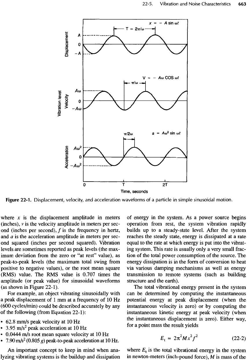
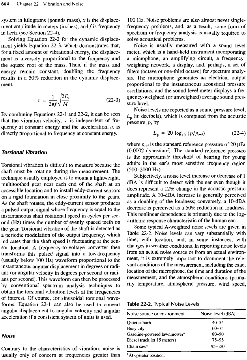
22-1.
The
three curves describe
exactly
the
same motion (displacement, velocity,
and
acceleration)
of a
single point
on the
object that
is
vibrating
—
all
as a
function
of
time.
All
curves have
the
same shape
and
repetition period
of T
seconds.
The
only
difference between these curves
is the
amplitude
(vertical) scale
and the
relative phase
(shift
in
time).
The
acceleration, velocity,
and
displacement
amplitudes
of a
sinusoidal signal
are
related
to
each
other
by
x
-
v
-
a
(22-1)
2«/
47C
2
/
2
where
x is the
displacement amplitude
in
meters
(inches),
v is the
velocity amplitude
in
meters
per
sec-
ond
(inches
per
second),
/ is the
frequency
in
hertz,
and
a is the
acceleration amplitude
in
meters
per
sec-
ond
squared (inches
per
second squared). Vibration
levels
are
sometimes reported
as
peak levels (the max-
imum
deviation
from
the
zero
or "at
rest"
value),
as
peak-to-peak levels (the maximum total swing
from
positive
to
negative values),
or the
root mean square
(RMS)
value.
The RMS
value
is
0.707
times
the
amplitude
(or
peak value)
for
sinusoidal
waveforms
(as
shown
in
Figure
22-1).
For
example,
an
object vibrating sinusoidally
with
a
peak displacement
of 1 mm at a
frequency
of 10 Hz
(600
cycles/min)
could
be
described accurately
by any
of
the
following
(from
Equation 22-1):
•
62.8 mm/s peak velocity
at 10 Hz
•
3.95 m/s
2
peak acceleration
at 10 Hz
•
0.0444
m/s
root mean square velocity
at 10 Hz
•
7.90
m/s
2
(0.805
g)
peak-to-peak acceleration
at 10 Hz.
An
important concept
to
keep
in
mind when ana-
lyzing
vibrating systems
is the
buildup
and
dissipation
of
energy
in the
system.
As a
power source begins
operation
from
rest,
the
system vibration rapidly
builds
up to a
steady-state
level.
After
the
system
reaches
the
steady state, energy
is
dissipated
at a
rate
equal
to the
rate
at
which energy
is put
into
the
vibrat-
ing
system.
This
rate
is
usually only
a
very small
frac-
tion
of the
total power consumption
of the
source.
The
energy
dissipation
is in the
form
of
conversion
to
heat
via
various damping mechanisms
as
well
as
energy
transmission
to
remote systems (such
as
building
structure
and the
earth).
The
total vibrational energy present
in the
system
can be
determined
by
computing
the
instantaneous
potential energy
at
peak displacement (when
the
instantaneous velocity
is
zero)
or by
computing
the
instantaneous kinetic energy
at
peak velocity (when
the
instantaneous displacement
is
zero).
Either
way,
for
a
point mass
the
result yields
E
1
=
27C
2
MjC
2
/
2
(22-2)
where
E
t
is the
total vibrational energy
in the
system
in
newton-meters
(inch-pound force),
M is
mass
of the
Figure
22-1.
Displacement,
velocity,
and
acceleration
waveforms
of a
particle
in
simple
sinusoidal
motion.
system
in
kilograms (pounds mass),
x is the
displace-
ment
amplitude
in
meters (inches),
and
/is
frequency
in
hertz (see
Section
22-4).
Solving Equation 22-2
for the
dynamic displace-
ment yields Equation 22-3, which demonstrates that,
for
a fixed
amount
of
vibrational energy,
the
displace-
ment
is
inversely proportional
to the
frequency
and
the
square root
of the
mass. Thus,
if the
mass
and
energy remain constant, doubling
the
frequency
results
in a 50%
reduction
in the
dynamic displace-
ment.
'
-
IF/]!'
(2M
>
By
combining Equations 22-1
and
22-2,
it can be
seen
that
the
vibration velocity,
v, is
independent
of
fre-
quency
at
constant energy
and the
acceleration,
a,
is
directly
proportional
to
frequency
at
constant energy.
Torsional
Vibration
Torsional vibration
is
difficult
to
measure because
the
shaft
must
be
rotating during
the
measurement.
The
technique usually employed
is to
mount
a
lightweight,
multitoothed gear near each
end of the
shaft
at an
accessible
location
and to
install eddy-current
sensors
on
a
rigid foundation
in
close proximity
to the
gears.
As
the
shaft
rotates,
the
eddy-current sensor produces
a
pulsed output signal whose frequency
is
equal
to the
instantaneous
shaft
rotational speed
in
cycles
per
sec-
ond
(Hz) times
the
number
of
evenly spaced teeth
on
the
gear. Torsional vibration
of the
shaft
is
detected
as
a
periodic
modulation
of the
output frequency, which
indicates that
the
shaft
speed
is fluctuating at the
sen-
sor
location.
A
frequency-to-voltage converter then
transforms
this pulsed signal into
a
low-frequency
(usually
below
100 Hz)
waveform proportional
to the
instantaneous
angular displacement
in
degrees
or
radi-
ans
(or
angular velocity
in
degrees
per
second
or
radi-
ans
per
second).
This
waveform
can
then
be
processed
by
conventional spectrum analysis techniques
to
obtain
the
torsional vibration levels
at the
frequencies
of
interest.
Of
course,
for
sinusoidal
torsional
wave-
forms,
Equation 22-1
can
also
be
used
to
convert
angular displacement
to
angular velocity
and
angular
acceleration
if a
consistent system
of
units
is
used.
Noise
Contrary
to the
characteristics
of
vibration, noise
is
usually
only
of
concern
at
frequencies greater than
100 Hz.
Noise
problems
are
also
almost never
single-
frequency
problems, and,
as a
result, some
form
of
spectrum
or
frequency analysis
is
usually required
to
solve acoustical problems.
Noise
is
usually measured with
a
sound level
meter, which
is a
hand-held instrument incorporating
a
microphone,
an
amplifying circuit,
a
frequency-
weighting network,
a
display, and, perhaps,
a set of
filters
(octave
or
one-third octave)
for
spectrum analy-
sis.
The
microphone generates
an
electrical output
proportional
to the
instantaneous acoustical pressure
oscillations,
and the
sound level meter displays
a
fre-
quency-weighted
(or
unweighted) average sound pres-
sure level.
Noise levels
are
reported
as a
sound pressure level,
Lp
(in
decibels), which
is
computed
from
the
acoustic
pressure,
/?,
by
L
p
=
20
Iog
10
(p/p
Kf
)
(22-4)
where
p
ref
is the
standard reference pressure
of 20
juPa
(0.0002
dynes/cm
2
).
The
standard reference pressure
is the
approximate threshold
of
hearing
for
young
adults
in the
ear's
most sensitive frequency region
(500-2000
Hz).
Subjectively,
a
noise level increase
or
decrease
of 1
dBA
is
difficult
to
detect with
the ear
even though
it
does represent
a 12%
change
in the
acoustic pressure
amplitude.
A
10-dBA
increase
is
generally perceived
as
a
doubling
of the
loudness; conversely,
a
10-dBA
decrease
is
perceived
as a 50%
reduction
in
loudness.
This nonlinear dependence
is
primarily
due to the
log-
arithmic response characteristic
of the
human ear.
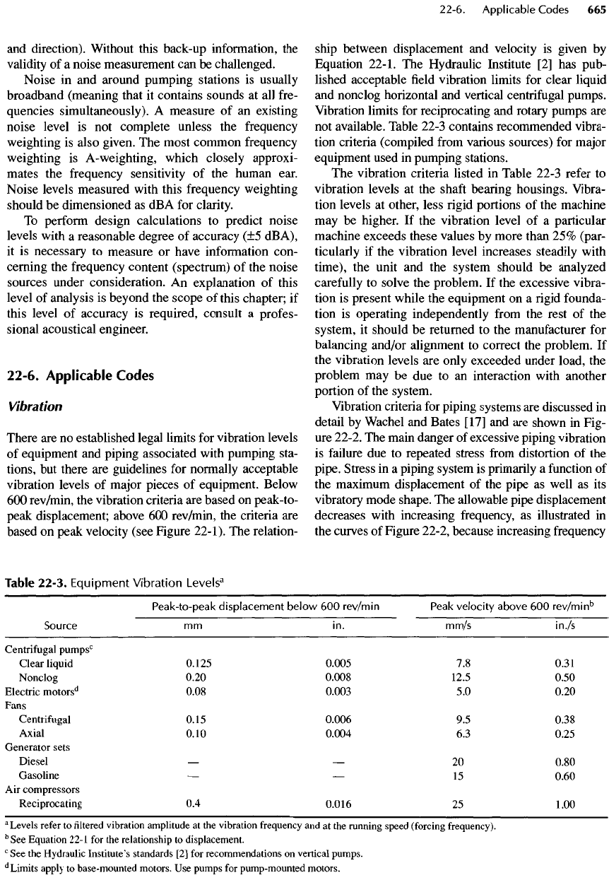
Some typical A-weighted noise levels
are
given
in
Table 22-2. Noise levels
can
vary substantially with
time, with location, and,
in
some instances, with
changes
in
weather conditions.
In
reporting noise levels
from
an
actual noise source
or
from
an
actual environ-
ment,
it is
extremely important
to
document
the
rele-
vant
conditions
of the
measurement, including
the
exact
location
of the
microphone,
the
time
and
duration
of the
measurement,
and the
atmospheric
conditions
(prima-
rily
temperature, atmospheric pressure, wind speed,
Table
22-2.
Typical
Noise
Levels
Noise
source
or
environment Noise level (dBA)
Quiet suburb
40-55
Busy
city
60-75
Gasoline-powered
lawnmower
1
80-90
Diesel truck
(at 15
meters)
75-95
Chain
saw
a
95-120
3
At
operator
position.
and
direction). Without this back-up information,
the
validity
of a
noise measurement
can be
challenged.
Noise
in and
around pumping stations
is
usually
broadband
(meaning that
it
contains sounds
at all
fre-
quencies simultaneously).
A
measure
of an
existing
noise level
is not
complete unless
the
frequency
weighting
is
also given.
The
most common frequency
weighting
is
A-
weighting,
which closely approxi-
mates
the
frequency
sensitivity
of the
human ear.
Noise levels measured with this frequency weighting
should
be
dimensioned
as dBA for
clarity.
To
perform design calculations
to
predict
noise
levels
with
a
reasonable degree
of
accuracy
(±5
dBA),
it
is
necessary
to
measure
or
have information con-
cerning
the
frequency content (spectrum)
of the
noise
sources under consideration.
An
explanation
of
this
level
of
analysis
is
beyond
the
scope
of
this chapter;
if
this
level
of
accuracy
is
required, consult
a
profes-
sional acoustical engineer.
22-6.
Applicable
Codes
Vibration
There
are no
established legal limits
for
vibration levels
of
equipment
and
piping associated with pumping sta-
tions,
but
there
are
guidelines
for
normally acceptable
vibration
levels
of
major
pieces
of
equipment. Below
600
rev/min,
the
vibration criteria
are
based
on
peak-to-
peak
displacement; above
600
rev/min,
the
criteria
are
based
on
peak velocity (see Figure 22-1).
The
relation-
ship between displacement
and
velocity
is
given
by
Equation
22-1.
The
Hydraulic Institute
[2] has
pub-
lished acceptable
field
vibration limits
for
clear liquid
and
nonclog horizontal
and
vertical
centrifugal
pumps.
Vibration limits
for
reciprocating
and
rotary pumps
are
not
available. Table 22-3 contains recommended vibra-
tion criteria (compiled
from
various sources)
for
major
equipment used
in
pumping stations.
The
vibration
criteria
listed
in
Table 22-3 refer
to
vibration levels
at the
shaft
bearing housings. Vibra-
tion
levels
at
other,
less
rigid
portions
of the
machine
may
be
higher.
If the
vibration level
of a
particular
machine exceeds these values
by
more than
25%
(par-
ticularly
if the
vibration level increases steadily with
time),
the
unit
and the
system should
be
analyzed
carefully
to
solve
the
problem.
If the
excessive vibra-
tion
is
present while
the
equipment
on a rigid
founda-
tion
is
operating independently
from
the
rest
of the
system,
it
should
be
returned
to the
manufacturer
for
balancing and/or alignment
to
correct
the
problem.
If
the
vibration levels
are
only exceeded under load,
the
problem
may be due to an
interaction with another
portion
of the
system.
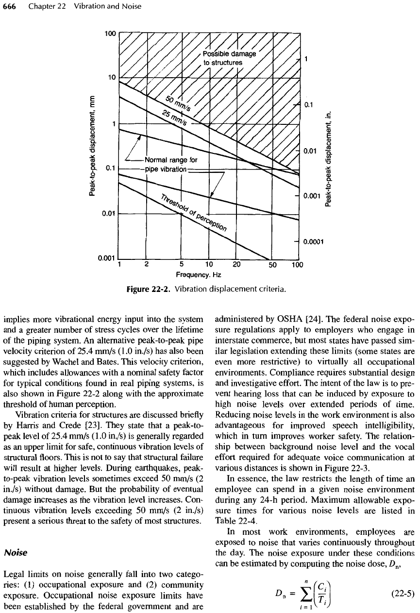
Vibration criteria
for
piping systems
are
discussed
in
detail
by
Wachel
and
Bates
[17]
and are
shown
in
Fig-
ure
22-2.
The
main danger
of
excessive piping vibration
is
failure
due to
repeated stress
from
distortion
of the
pipe. Stress
in a
piping system
is
primarily
a
function
of
the
maximum displacement
of the
pipe
as
well
as its
vibratory mode shape.
The
allowable pipe displacement
decreases with increasing frequency,
as
illustrated
in
the
curves
of
Figure 22-2, because increasing
frequency
Table
22-3.
Equipment
Vibration
Levels
3
Peak-to-peak
displacement below
600
rev/min
Peak
velocity above
600
rev/min
b
Source
mm in.
mm/s
in./s
Centrifugal
pumps
c
Clear liquid 0.125
0.005
7.8
0.31
Nonclog 0.20
0.008
12.5 0.50
Electric
motors
d
0.08
0.003
5.0
0.20
Fans
Centrifugal
0.15
0.006
9.5
0.38
Axial 0.10
0.004
6.3
0.25
Generator sets
Diesel
— — 20
0.80
Gasoline
— — 15
0.60
Air
compressors
Reciprocating
0.4
0.016
25
1.00
a
Levels
refer
to filtered
vibration
amplitude
at the
vibration
frequency
and at the
running
speed
(forcing
frequency).
b
See
Equation
22-1
for the
relationship
to
displacement.
c
See the
Hydraulic
Institute's
standards
[2] for
recommendations
on
vertical pumps.
d
Limits
apply
to
base-mounted
motors.
Use
pumps
for
pump-mounted
motors.
implies more vibrational energy input into
the
system
and
a
greater number
of
stress cycles over
the
lifetime
of
the
piping system.
An
alternative peak-to-peak pipe
velocity
criterion
of
25.4
mm/s
(1.0
in./s)
has
also been
suggested
by
Wachel
and
Bates. This velocity
criterion,
which
includes allowances
with
a
nominal
safety
factor
for
typical conditions
found
in
real piping systems,
is
also shown
in
Figure 22-2 along with
the
approximate
threshold
of
human perception.
Vibration criteria
for
structures
are
discussed
briefly
by
Harris
and
Crede
[23].
They state that
a
peak-to-
peak level
of
25.4 mm/s
(1.0
in./s)
is
generally regarded
as an
upper limit
for
safe,
continuous vibration levels
of
structural
floors.
This
is not to say
that structural failure
will
result
at
higher levels. During earthquakes, peak-
to-peak vibration levels sometimes exceed
50
mm/s
(2
in./s) without damage.
But the
probability
of
eventual
damage increases
as the
vibration level increases. Con-
tinuous
vibration levels exceeding
50
mm/s
(2
in./s)
present
a
serious threat
to the
safety
of
most structures.
Noise
Legal limits
on
noise
generally
fall
into
two
catego-
ries:
(1)
occupational exposure
and (2)
community
exposure. Occupational
noise
exposure limits have
been established
by the
federal government
and are
administered
by
OSHA
[24].
The
federal noise expo-
sure regulations apply
to
employers
who
engage
in
interstate commerce,
but
most states have passed sim-
ilar legislation extending these limits (some states
are
even more restrictive)
to
virtually
all
occupational
environments. Compliance requires substantial design
and
investigative
effort.
The
intent
of the law is to
pre-
vent
hearing loss that
can be
induced
by
exposure
to
high
noise levels over extended periods
of
time.
Reducing
noise
levels
in the
work environment
is
also
advantageous
for
improved speech intelligibility,
which
in
turn improves worker
safety.
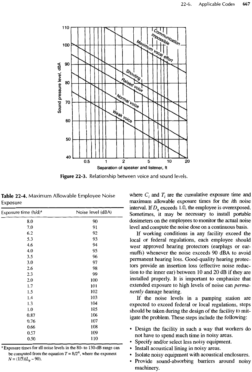
The
relation-
ship between background noise level
and the
vocal
effort
required
for
adequate
voice
communication
at
various
distances
is
shown
in
Figure 22-3.
In
essence,
the law
restricts
the
length
of
time
an
employee
can
spend
in a
given noise environment
during
any
24-h period. Maximum allowable expo-
sure times
for
various noise levels
are
listed
in
Table 22-4.
In
most work environments, employees
are
exposed
to
noise that varies continuously throughout
the
day.
The
noise exposure under these conditions
can
be
estimated
by
computing
the
noise
dose,
D
n
,
n
(c^
D
"
=
2r;
(22
'
5)
/
=
A
1
^
Figure
22-2.
Vibration
displacement criteria.
Table
22-4.
Maximum
Allowable
Employee
Noise
Exposure
Exposure
time
(h/d)
a
Noise
level
(dBA)
8.0 90
7.0 91
6.2 92
5.3 93
4.6 94
4.0 95
3.5
96
3.0 97
2.6 98
2.3 99
2.0 100
1.7 101
1.5
102
1.4
103
1.3
104
1.0
105
0.87
106
0.76
107
0.66
108
0.57
109
0.50
110
a
Exposure times
for all
noise levels
in the 80- to
130-dB
range
can
be
computed
from
the
equation
T =
S/2
N
,
where
the
exponent
N
=
(l/5)(L
p
-90).
where
C
1
and
T
1
are the
cumulative exposure time
and
maximum
allowable exposure times
for the
/th
noise
interval.
IfD
n
exceeds
1.0,
the
employee
is
overexposed.
Sometimes,
it may be
necessary
to
install portable
dosimeters
on the
employees
to
monitor
the
actual noise
level
and
compute
the
noise dose
on a
continuous basis.
If
working conditions
in any
facility
exceed
the
local
or
federal regulations, each employee should
wear
approved hearing
protectors
(earplugs
or
ear-
muffs)
whenever
the
noise exceeds
90 dBA to
avoid
permanent hearing loss. Good-quality hearing protec-
tors provide
an
insertion loss
(effective
noise
reduc-
tion
to the
inner ear) between
10 and 20 dB if
they
are
installed properly.
It is
important
to
emphasize that
extended exposure
to
high levels
of
noise
can
perma-
nently
damage hearing.
If
the
noise levels
in a
pumping station
are
expected
to
exceed federal
or
local regulations, steps
should
be
taken during
the
design
of the
facility
to
mit-
igate
the
problem.
These
steps include
the
following:
•
Design
the
facility
in
such
a way
that workers
do
not
have
to
spend much time
in
noisy
areas.
•
Specify
and/or select less noisy equipment.
•
Install acoustical lining
in
noisy areas.
•
Isolate noisy equipment with acoustical enclosures.
•
Provide sound-absorbing barriers around noisy
machinery.
Figure 22-3.
Relationship
between
voice
and
sound
levels.
