Pump Handbook by Igor J. Karassik, Joseph P. Messina, Paul Cooper, Charles C. Heald - 3rd edition
Подождите немного. Документ загружается.


3.8 VANE, GEAR, AND LOBE PUMPS 3.145
The total differential pressure P
d
is the algebraic difference between the outlet pressure
and the inlet pressure, with both expressed in the same units. This differential pressure
is used in the determination of power input and in evaluating the slip characteristics of
the pump:
(8)
The net inlet pressure P
net in
of a rotary pump is the difference between the inlet pressure
expressed in absolute units and the vapor pressure of the fluid expressed in absolute units:
(9)
Expressed as head of the pumped liquid, this is the net positive suction head, NPSH.
The required NPSH or net inlet pressure required P
nipr
is the minimum net inlet pressure
that can exist without the creation of enough vapor in the inlet to interfere with proper
operation of the pump.The inlet pressure usually is not the true minimum pressure in the
OTI volume.The flow of fluid in its passage through the OTI volume causes a fluid friction
pressure loss, which causes the pressure to drop below the inlet pressure at some point in
the OTI volume or inlet chamber. This loss increases with fluid velocity and hence with
pump speed and fluid viscosity. It is a function of the pump geometry, which determines
the fluid path lengths and local velocities where the fluid changes direction in flowing
around curves or corners in the pump OTI volume boundary.
The required net inlet pressure is established by the manufacturer for particular
speeds, pressures, and fluid characteristics. In practice, the pump user is warned that the
net inlet pressure is near or at the required net inlet pressure by noisy and rough opera-
tion of the pump caused by the incomplete filling of the CTIO volume with an accompa-
nying reduction in pump flow rate.
The two other pressure ratings used are the maximum allowable working pressure,
which is the maximum gage pressure at the outlet port permitted for safe operation. It is
usually determined by the stiffness and strength of the pump body and the type of seals
used. The maximum differential pressure is the maximum allowable difference between
the outlet pressure and the inlet pressure, measured in the same units, and is determined
by the capability of the rotating assembly and its fluid seal contact zones to withstand the
pressure difference between the OTO and OTI volumes.
Power Most of the pump input shaft power HP
in
(kW
in
) is the power imparted to the fluid
delivered by the pump at given operating conditions and is frequently called liquid or
hydraulic power HP
hyd
(kW
hyd
). A common unit used for expressing power ratings is horse-
power (kilowatts) and can be computed by the equation:
In USCS units (10)
In SI units
where the constant 1,714 (36) gives the hydraulic power input in hp (kW) when Q
d
is in gpm
(m
3
/h) and P
d
is the differential pressure in lb/in
2
(bar). This is the theoretical power or the
required power independent of mechanical friction power losses, and fluid friction power.
The mechanical friction power losses HP
losses
(kW
losses
) have two components. One is the
mechanical friction power required by the elements outside the pumping chamber, such as
the bearings and seals, and is usually independent of the fluid being pumped, the pump
speed, and the differential pressure. The mechanical friction power inside the pumping
chamber depends also on the pump speed and pump differential pressure, but it also
depends on the viscosity and lubricity of the fluid.
The fluid friction power losses, or viscous power losses, are a function of the viscosity of
the liquid being handled and on the shear rate in the fluid, which is a function of pump
design and pump speed. When handling high-viscosity liquids, the viscous friction power
kW
hyd
Q
d
P
d
36
HP
hyd
Q
d
P
d
1714
P
net in
P
in
P
vapor
P
d
P
out
P
in

3.146 CHAPTER THREE
grows with viscosity, even if speed and pressure remain constant.This power loss depends on
a number of design features of the pump and usually will grow proportionally to the viscos-
ity to the nth power, where n usually ranges between 0.3 and 1.0 for most rotary pumps.
Increasing any clearances in a pump reduces the shear stress in the liquid in those clearances
at any given speed and consequently reduces the torque to overcome the viscous friction.
The useful output power HP
out
is less than HP
hyd
by an amount HP
slip loss
due to leakage
Q
slip
through the clearances. Thus, overall efficiency E
overall
= HP
out
/HP
in
, where (for SI units,
substitute kW for HP)
(11)
Efficiency Rotary pumps are measured by their volumetric, mechanical, and (as just
defined) overall efficiencies. This often requires certain trade-offs when selecting a pump
for a given set of conditions since a rotary pump does not have a single best efficiency point
(BEP) the way a centrifugal pump does.
Volumetric efficiency E
vol
compares actual to theoretical output flows. It is an indication
of both a pump’s capability to handle a given differential pressure and viscosity and, in the
case of older pumps, an indication of possible internal wear. The more flow a pump can
deliver under these conditions, the higher its volumetric efficiency will be. The volumetric
efficiency of a rotary pump is defined as
(12)
where Q
d
displacement or geometric flow delivered, in gpm (m
3
/hr)
Q
s
slip flow, in gpm (m
3
/hr)
The positive displacement nature of rotary pumps makes them suitable for many
metering applications. The pump would be a perfect metering device with zero errors if
there were no slip. It would be considered a dependable meter if the slip were low or main-
tained constant over the entire range of operating conditions. A useful ratio in a compari-
son of different types of rotary pumps for a given metering application is the ratio of
minimum flow rate in any of the operating conditions to the maximum flow rate in any of
the operating conditions at a given speed. In variable-speed applications, the ratio of min-
imum volumetric efficiency to maximum volumetric efficiency is substituted. The meter-
ing effectiveness is highest as this ratio approaches unity. The difference between this ratio
and 1 100 is the percentage of change that can be expected either in the flow rate of the
pump or in the total amount of fluid displaced for a given number of revolutions under
extremes of operating conditions (such as pressures, temperatures, viscosities, and so on)
Volumetric efficiencies fall in the range of 65 to 98 percent for most rotary pumps. A
changing volumetric efficiency over time usually indicates changing system conditions of
service or pump wear.
Mechanical efficiency E
mech
is the ratio of the pump input hydraulic power to input shaft
power. It can also be looked at as the comparison of theoretical input power required for the
actual power required. The less power a pump requires to produce a given amount of
hydraulic work (output), the higher its mechanical efficiency. The total volume of fluid Q
d
han-
dled by the pump is larger than Q when slip is present.The amount of slip actually represents
wasted power and affects pump efficiency. The difference between shaft power input and
hydraulic power input consists of the power lost to mechanical friction and the power lost to
fluid friction (a function of the viscosity of the fluid and pump shear stresses on the fluid).The
mechanical efficiency of a rotary pump is found by the equation
(13)
Overall efficiency E
overall
is the most important efficiency because it alone determines
the overall effectiveness of a pump for an application. That is, knowing only the volumet-
ric or mechanical efficiencies can result in misleading conclusions. Only with a satisfactory
E
mech
e
HP
hyd
HP
in
f e
HP
hyd
HP
hyd
HP
losses
f
E
vol
Q
d
Q
s
Q
d
HP
in
HP
slip loss
HP
mech loss
HP
friction losses
HP
out
3.8 VANE, GEAR, AND LOBE PUMPS 3.147
overall efficiency one can be reasonably assured of overall satisfactory performance. Over-
all efficiency is defined in terms of E
mech
and E
vol
as follows:
in USCS units (14)
in SI units
Another way of looking at overall efficiency is
(15)
Pump Performance Figures 18, 19, and 20 show the change in displacement capacity Q
d
,
flow rate or capacity Q
c
, and slip Q
s
as the differential pressure across the pump P
d
, the vis-
cosity y, and the pump speed N are varied. Several assumptions are made in these graphs.
It is assumed that inlet conditions are satisfactory and that there is no inlet effect on the
pump capacity over the charted range. It is assumed that the fluid is Newtonian and the
liquid is incompressible. In Figures 18 and 19, it is assumed that viscosity is constant and
relatively low, and that the speed is within the normal range of the pump. In Figure 20, it
is assumed that both pressure and speed are within the normal ratings of the pump.
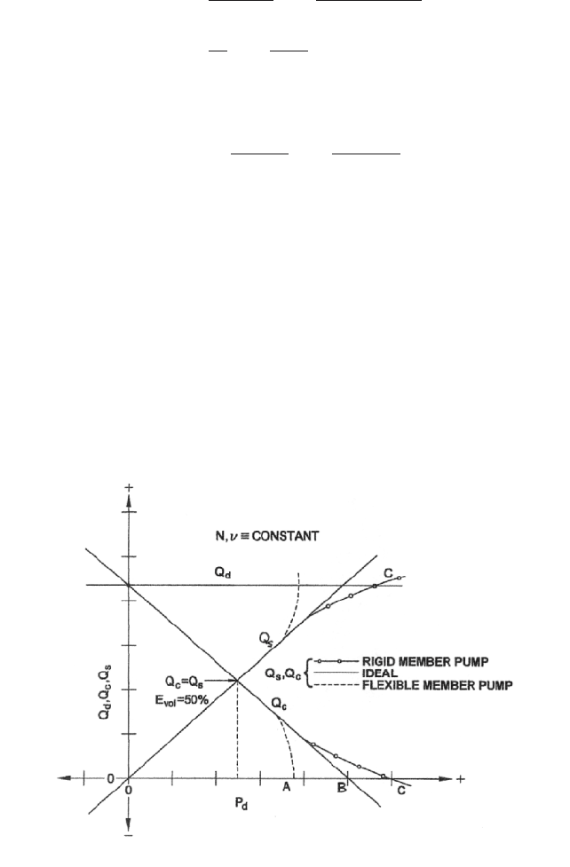
The graph in Figure 18 is plotted with the flow rate, slip, and displacement flow rate
on a linear scale as the ordinate (Y-axis) and pressure on a linear scale as the abscissa (X-
axis). A further assumption is that the clearances and viscosity are such that the slip
increases proportionately with pressure.The solid lines are the ideal characteristics when
secondary effects are neglected. It may be noted that at zero pressure, slip Q
s
is zero and
Q
c
equals Q
d
. As the pressure increases, Q
s
increases until it equals Q
d
at pressure B. If the
pressure imposed on the pump were to increase past this point, Q
s
would exceed Q
d
and
the flow through the pump would be from outlet to inlet, causing a negative Q
c
.
E
overall
e
Q
actual
Q
theoretical
f e
HP
theoretical
HP
actual
f
E
vol
E
mech
e
Q
c
Q
d
f e
kW
hyd
kW
in
f
E
overall
e
Q
d
Q
slip
Q
d
f e
HP
hyd
HP
hyd
HP
losses
f
FIGURE 18 Varation of Q
d
,Q
c
, and Q
s
with P
d
, N and v constant
3.148 CHAPTER THREE
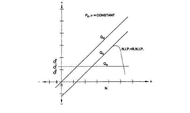
FIGURE 19 Varations of Q
d
, Q
c
, and Q
s
with N, P
d
, and v constant
Although rotary pumps do not operate in this end of the pressure range, the condition
of pressure B can be reached when a valve is closed, blocking the outlet of the pump. Pres-
sure B, then, represents dead-ended pressure developed by a rotary pump when its outlet
line is blocked. Should Q
d
be numerically equal to 100 in whichever units are used, then
the plot of Q
c
is numerically equal at each point to the volumetric efficiency E
vol
of the
pump and Q
c
becomes zero at pressure B.
Pressure B data is usually not available from pump manufacturers since these values
are usually far beyond the normal safe pressure rating of the pump. However, they can be
estimated by extrapolating the data given. Cautions should be observed, however. A flex-
ible member can quickly reach a pressure at which flexible member deflection becomes
excessive, and the pressure at which Q
c
equals zero is very quickly reached. This is illus-
trated in Figure 18 by the dashed line breaking away from the solid Q line and intersect-
ing the abscissa at pressure point A. This characteristic of flexible member pumps
provides a self-limited maximum pressure should the pump be dead-ended. In rigid rotor
pumps, as the pressure increases beyond the normal operating range, deflections of the
shafts and rotors bring the rotors into heavy bearing contact with the body chamber walls,
reducing the dimensions of the slip clearance path. The dashed line leaving the Q
c
and Q
s
curves and intersecting the abscissa and Q
d
line at pressure point C illustrates this. Con-
sequently, the zero flow pressure, which is ideally at point B, may be considerably differ-
ent from this extrapolated value, and it should be measured if it is important to the
application.
Under the same assumptions given for Figure 18, Figure 19 shows the relative indepen-
dence of the slip with speed when differential pressure is constant. Here the chart of Q inter-
sects the abscissa at the point where the speed is low enough for the displacement flow rate
to be equal to the slip at the pressure of operation. The speed at which Q
d
equals 2 Q
s
is
the speed at which Q
s
equals Q
c
and the volumetric efficiency E
vol
becomes 50 percent.
As the speed increases, the pumping action of the shear stress in the clearances tends
to reduce the slip below the ideal line. However, for most rotary pumps, the detrimental
effects of increasing the speed above the normal operating range is usually caused by inlet
losses in the pump.This effect is cavitation and is illustrated by the dashed line, for which
the net inlet pressure (N. I. P.) or NPSH is less than that required.
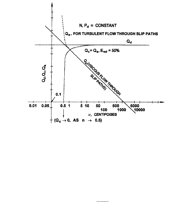
Figure 20 shows the effect of viscosity on the slip and flow rate in a rotary pump. The
graphs are on a log-log scale. In this chart, it is assumed that the pressure, speed, and vis-
cosity combine to keep the flow through clearances of the pump in the laminar or “viscous”
flow region.
3.8 VANE, GEAR, AND LOBE PUMPS 3.149
FIGURE 20 Varations of Q
d
, Q
o
, and Q
s
with v, N and P
d
constant
As viscosity increases, slip Q
s
becomes very small and the flow rate of the pump Q
c
approaches the displacement flow rate Q
d
. As the viscosity decreases, the slip very rapidly
approaches the displacement flow rate and the flow rate of the pump drops rapidly to zero
or to a negative quantity. For any given pump with speed N and differential pressure P
d
,
there is a viscosity below which the slip flow, through clearances of the pump, will change
to a turbulent flow. It is unlikely that this change will occur simultaneously through all
slip paths. However, once it begins to occur, the slip will increase much more rapidly with
further reductions in viscosity because of the turbulent flow relationship of the slip, pres-
sure, and viscosity expressed in Equation 16:
(16)
where x usually is in the range of four to 10, and K is a constant.
Volumetric efficiency E
vol
drops very rapidly with the viscosity if the viscosity is lower
than that required for 50 percent volumetric efficiency (represented by the crossover point
of the slip and capacity curves). This crossover point occurs for most rotary pumps oper-
ating at rated differential pressure P
d
for viscosities between 0.1 and 10 centipoise. For the
majority of commercially available models, this point usually falls in the viscosity range of
0.3 to 3.0 centipoise at the maximum rated differential pressure.
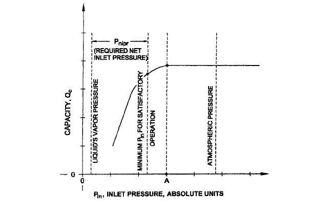
The effect of inlet pressure on the capacity can be seen clearly if all secondary effects are
eliminated.This assumes the pump is operating within its normal pressure limits and speed
range and that viscosity is high enough to reduce the slip to a negligible value. A graph of
the capacity as a function of inlet pressure is shown in Figure 21 with these assumptions.
There is no change in capacity or flow rate as inlet pressure is lowered until the pres-
sure reaches pressure A on the graph. If the inlet pressure were lowered further, the flow
rate would drop as shown. The cause of this drop is complex in detail but simple in con-
cept. The liquid flow from the inlet port through the inlet chamber of the pump causes a
pressure drop, which causes a minimum pressure point somewhere in the inlet chamber.
When the pressure in the liquid at this minimum pressure point approaches the vapor
pressure of the liquid, vapor begins to form there. When the amount and time persistence
of this vapor cause the vapor to be swept into the CTIO volume of the pump, the amount
Q
s
KP
d
1>2
v
1>x
3.150 CHAPTER THREE
FIGURE 21 Varations of Q
c
and P
in
with other operating conditions constant
of liquid in this volume is reduced, leaving a deficiency of liquid volume. For example, if
half the fluid volume swept from the inlet chamber is vapor, then only half the normal-
capacity liquid volume is available at the outlet chamber, and the flow rate is reduced
accordingly.
An increase in speed would mean an increase in flow rate, all other things being equal.
This would increase the pressure drop between the inlet port and the inlet chamber and
correspondingly increase the absolute inlet pressure (which is measured at the inlet port)
at which the flow rate would begin to drop (pressure A). Correspondingly, if the speed and
flow rate were constant and the viscosity increased, the pressure drop between the inlet
port and the minimum pressure point in the inlet chamber would increase with viscosity.
This also would cause pressure A to move to higher inlet absolute pressures. Operation
with absolute inlet pressures below pressure A for any given speed and viscosity is usually
unsatisfactory both because of the drop in capacity (and hence in volumetric efficiency) and
because of the noisy and rough operation caused by the formation and collapse of the vapor.
For lower viscosity liquids where the collapse of the vapor bubbles may be quite rapid, cav-
itation may cause a significant amount of damage to the body or rotor surfaces. It is impor-
tant to understand that cavitation damage may occur even though the absolute inlet pressure
is above pressure A.Locations may be found in the inlet chamber, particularly where the flow
direction changes rapidly, as around sharp corners, where vapor formation in the form of very
fine bubbles, and hence cavitation, may occur. However, these vapor cavities may be swept
into higher pressure regions of the inlet chamber and collapse near body or rotor surfaces to
cause cavitation damage,although the capacity of the pump is not affected. For any given vis-
cosity then, there is an upper limit to the speed at which the pump can be operated.
The inlet pressure may be allowed to drop slightly below pressure A without a signifi-
cant deterioration in pump performance. However, there is a point at which the pressure
becomes too low for satisfactory pump operation. This pressure determines the required
net inlet pressure P
nipr
or NPSHR for the particular pump and the particular set of oper-
ation conditions. For any given set of operating conditions, satisfying the required net inlet
pressure or NPSHR is a main limitation on the pump operating speed.
The other main limit on the pump operating speed is the pump outlet pressure. In every
application, some fluid frictional losses occur in the outlet system of the pump. Even if the
pump outlet is opened to the atmosphere, a pressure drop exists between some maximum
pressure point in the pump outlet chamber and the pump outlet itself. However, by far, the
3.8 VANE, GEAR, AND LOBE PUMPS 3.151
most common situation is one in which a significant fluid friction pressure is developed in
the system external to the outlet of the pump. This fluid pressure usually is a function of
pump capacity and therefore of pump speed. If the inlet conditions are maintained to keep
the inlet pressure above pressure A as the pump speed increases, a speed will be reached at
which the pump outlet pressure equals the outlet pressure rating of the pump. Operating at
speeds higher than this will cause the pump outlet pressure to exceed the rated pressure
and this could result in damage to the pump.
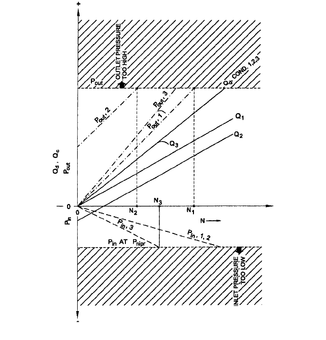
These two limits on pump speed are illustrated in Figure 22. Three sets of operating
conditions are shown. In operating condition 1, the outlet system friction resisting liquid
flow (outlet system impedance) is relatively high and the outlet pressure developed by the
flow is directly proportional to the pump flow rate (laminar flow). No static head exists in
the system, and the outlet pressure is developed only when the pump causes liquid to flow
through the outlet system. The liquid viscosity is assumed to be low enough to permit
some slip in the pump. The net inlet pressure is assumed to be above pressure A over the
range of operations shown.
Operating condition 2 is the same as operating condition 1, except that a static head
(static outlet pressure) exists in the outlet system. This head is the pressure at which the
chart of pump outlet pressure in condition 2 intercepts the zero speed line.
Operating condition 3 is one in which the impedance to the liquid flow in the outlet sys-
tem is relatively low, but the liquid viscosity is relatively high. In this condition, Q
c,
shown
FIGURE 22 P
in
and P
out
limitations on pump speed
3.152 CHAPTER THREE
as Q
3
, is equal to the displacement flow rate Q
d
as speed is increased until a speed is reached
at which the available net inlet pressure of the pump drops to the required net inlet pres-
sure of the pump. If the speed is increased beyond this point, the capacity of the pump would
drop rapidly as an ever-increasing part of the pump fluid becomes vapor instead of liquid.
The upper limit of speed for satisfactory operation of the pump is shown as N
1
, N
2
, and
N
3
for the three conditions described. The locations of N
1
, N
2
, and N
3
on the speed axis are
independent of each other because they depend primarily on the operating conditions of the
pump, the system in which it operates, and on the conditions of the pumped fluid. For exam-
ple, a negative head in the outlet system could cause N
3
to move to a higher value than N
2
,
and N
2
to move to a higher value than N
1
. Operation with a liquid with lower viscosity (but
still sufficient to reduce the slip to zero) could cause N
3
to be higher than N
1
.
In most applications, one of the two limits described determines the maximum permit-
ted speed of pump operation. However, if neither of these conditions limits the speed and the
speed is continuously increased, a speed will be reached at which the peripheral velocity of
the rotors will exceed the cavitation velocity of the liquid.A further increase in speed beyond
this point would be limited by the cavitation occurring at the rotor outer radial surfaces.
SPECIFICATIONS, INDUSTRIES, AND APPLICATIONS ______________________
In addition to the many application-oriented classifications for vane, gear, or lobe pumps,
many technical classifications are also issued by various industrial, governmental, or even
military organizations. It is also important for both the manufacturer and the user to
know of any voluntary or regulatory specifications governing the construction and mate-
rials of the pumps destined for use in a specific industry and application.
Many industry-based specifications, such as the International Association of Milk, Food,
and Environmental Sanitarians, the United States Public Health Service, and the Dairy
Industry Committee, have jointly issued specifications called “The 3-A Sanitary Standards
for Pumps for Milk and Milk Products.” These standards govern the materials of construc-
tion of the pump, the surface finish and shape details of the contact surfaces, the finish and
shape of external surfaces, the method of mounting, and restrictions on gaskets, seals, and
other pump auxiliary features. Pumps constructed to meet 3-A Sanitary Standards are
called sanitary pumps and carry a 3-A seal of approval mounted on the pump body. Similar
specifications have been developed by the International Association of Milk, Food, and Envi-
ronmental Sanitarians, the United States Public Health Service, the United States Depart-
ment of Agriculture, the American Poultry Industries, and the Dairy and Food Industries
Supply Association to cover design features used in the handling of cracked eggs.
Standards for pumps used in various processes in the petroleum industry are con-
cerned with the materials and design features that are intended to prevent catastrophic
failures when explosive, flammable, or toxic fluids are being handled. Others generated by
governmental agencies and professional societies, such as the American Society of
Mechanical Engineers and the American Petroleum Institute Standard 676, establish
manufacturing procedures and design limitations on pumps for refineries, nuclear power
stations, and so on. In these cases, the terms sanitary, aseptic, explosion proof, API pump
or N stamp are not merely generic terms and cannot be casually applied. They must
instead be carefully applied and used only when the manufacturer warrants that the
pumps actually meet these specifications. In addition, as an unavoidable consequence, the
cost of manufacturing pumps to meet any of these standards makes them more expensive
than pumps built for general service applications.
Rotary pumps are used for both metering and transfer applications; so, most vane,
gear, and lobe pumps are found in these services. Metering pumps tend to be smaller and
operate with varying flow rates. Transfer pumps typically have a fixed speed, although
variable speed units are becoming more common as the cost for this equipment falls.
In general, the three most basic applications for these pumps are as follows:
1. Liquid handling In this class, well over 2,000 fluids are pumped and performance
is judged on the pump’s capability to handle the specific liquids, and the hydraulic
power generated by the pump is a secondary consideration.

3.8 VANE, GEAR, AND LOBE PUMPS 3.153
2. Hydraulic fluid power In this class, the hydraulic power generated by the pump
is used to actuate valves, pistons, cylinders, rotary actuators, and similar devices.
Pumps in this class are usually vane, gear, piston, or screw types and are designed for
pressures up to 9,000 lb/in
2
(620 bar) on selected hydraulic power fluids.
3. Commercial and retail In this class are the pumps designed for a single specific
use, application, or even fluid. Pumps in this miscellaneous class include everything
from miniature pumps for home aquariums to well water pumps for agricultural use
to fuel injection pumps for automobiles.
Among these three application areas, the most common is liquid handling tasks, and
they make up the largest percentage of uses for rotary vane, gear, and lobe pumps.
Markets and Applications The markets and applications served by vane, gear, and lobe
pumps are among the broadest of all rotary pumps. Although it would not be possible to
list every application served by these pumps, a broad sampling of the more common ones
is shown in Table 3.
SUMMARY __________________________________________________________
In this section, we have discussed vane, gear, and lobe pumps in a general sense and cov-
ered many of the technical attributes that give them their unique characteristics. From an
applications standpoint, the advantages these pumps have over other types can be sum-
marized in Table 4.
TABLE 3 Markets and applications
A
n
im
a
l R
e
n
d
e
rin
g
s In
d
u
stry
G
e
n
e
ra
l tra
n
sfe
rrin
g
to
b
u
rn
e
rs
o
f:
•
a
n
im
a
l fe
e
d
•
b
e
e
f b
y-p
ro
d
u
cts
•
b
o
n
e
m
e
a
l
•
m
o
lte
n
fa
ts
•
p
o
u
ltry b
y
-p
ro
d
u
cts
A
u
to
m
o
b
ile
In
d
u
s
try
D
istrib
u
tio
n
a
n
d
a
sse
m
b
ly lin
e
su
p
p
ly o
f:
•
g
re
a
s
e
•
lu
b
rica
tin
g
o
il
•
m
o
to
r fu
e
l
•
p
a
in
t, la
cq
u
e
rs a
n
d
th
in
n
e
rs
•
te
st sta
n
d
s
yste
m
s
C
h
e
m
ic
a
l In
d
u
stry
A
n
y p
ro
ce
ss o
r d
is
trib
u
tio
n
syste
m
h
a
n
d
lin
g
o
f:
•
a
cid
s
•
a
d
h
e
sive
s
•
b
le
a
ch
e
s
•
ca
u
stics
•
c
e
llu
lo
se
a
ce
ta
te
•
g
lyce
rin
•
n
itra
te
s
C
o
sm
e
tics a
n
d
S
o
a
p
In
d
u
stry
N
o
n- e
m
u
lsifyin
g
su
p
p
ly to
p
a
cka
g
in
g
m
a
ch
in
e
ry
o
f:
•
d
e
te
rg
e
n
t
•
la
n
o
lin
•
liq
u
e
fie
d
so
a
p
•
sh
a
m
p
o
o
F
o
o
d
P
ro
d
u
cts In
d
u
stry
G
e
n
e
ra
l p
ro
c
e
ss tra
n
sfe
rrin
g
o
f:
•
co
co
n
u
t o
il
•
co
rn
o
il
•
fish
o
ils
•
g
lu
c
o
se
•
g
lyce
rin
•
la
rd
•
m
ilk a
n
d
m
ilk b
y p
ro
d
u
c
ts
•
m
o
la
ss
e
s
•
p
a
lm
o
il
•
su
cro
se
so
lu
tio
n
s
•
ve
g
e
ta
b
le
sh
o
rte
n
in
g
G
e
n
e
ra
l In
d
u
stry a
n
d
O
E
M
s
V
a
rio
u
s flu
id
h
a
n
d
lin
g
re
q
u
ire
m
e
n
ts fo
r:
•
b
u
rn
e
rs a
n
d
h
e
a
te
r se
ts
•
ce
n
trifu
g
e
se
p
a
ra
to
r syste
m
s
•
co
o
kin
g
fa
t filtra
tio
n
u
n
its
•
filte
rin
g
a
n
d
m
e
te
rin
g
u
n
its
•
flu
id
re
cla
m
a
tio
n
syste
m
s
•
h
yd
ra
u
lic a
u
to
lifts a
n
d
e
le
va
to
rs
•
lu
b
e
o
il su
p
p
ly
u
n
its fo
r ro
ta
tin
g
e
q
u
ip
m
e
n
t
•
m
a
ch
in
e
ry co
o
la
n
t a
n
d
lu
b
ric
a
n
t circu
la
tio
n
•
p
a
in
t sp
ra
y b
o
o
th
s
•
ro
o
fin
g
ta
r syste
m
s
•
te
x
tile
d
ye
in
g
a
n
d
p
rin
tin
g
m
a
ch
in
e
ry
•
w
o
o
d
p
re
se
rv
a
tio
n
m
a
ch
in
e
ry
M
a
rin
e
In
d
u
stry
U
n
lo
a
d
in
g
, ta
n
k strip
p
in
g
a
n
d
e
n
g
in
e
ro
o
m
su
p
p
ly o
f:
•
a
sp
h
a
lt
•
h
e
a
tin
g
o
il
•
h
e
a
vy fu
e
l o
il
•
m
a
rin
e
d
ie
se
l o
il
•
lu
b
ric
a
tin
g
o
il
•
m
o
la
ss
e
s
P
a
in
t a
n
d
L
a
cq
u
e
r In
d
u
s
try
V
a
rio
u
s
p
ro
ce
s
s h
a
n
d
lin
g
a
p
p
lica
tio
n
s fo
r:
•
d
ye
s a
n
d
p
ig
m
e
n
ts
•
la
cq
u
e
r
•
la
te
x
•
p
a
in
t
•
tita
n
iu
m
d
io
xid
e
slu
rry
•
th
in
n
e
rs a
n
d
so
lve
n
ts
P
e
tro
le
u
m
In
d
u
stry
B
le
n
d
in
g
, p
a
ck
a
g
in
g
, a
n
d
u
n
lo
a
d
in
g
o
f:
•
a
sp
h
a
lt
•
b
itu
m
e
n
•
cre
o
so
te
•
g
re
a
s
e
•
fu
e
l o
il
•
h
e
a
vy fu
e
l o
il
•
lu
b
ric
a
tin
g
o
ils
P
u
lp
a
n
d
P
a
p
e
r In
d
u
stry
V
a
rio
u
s g
e
n
e
ra
l m
ill a
n
d
co
a
tin
g
a
p
p
lica
tio
n
s fo
r:
•
a
d
h
e
siv
e
s
•
b
la
ck liq
u
o
r
•
d
e- i n
kin
g
s
o
lve
n
ts
•
fu
e
l o
il
•
p
rin
tin
g
in
k
•
s
u
lfa
te
so
a
p
•
ta
ll o
il
•
tita
n
iu
m
d
io
xid
e
slu
rry
•
tu
rp
e
n
tin
e
•
visco
se
•
w
a
ste
p
o
n
d
re
cyclin
g
•
w
h
ite
liq
u
o
r
P
la
stics a
n
d
P
e
tro
ch
e
m
ica
l In
d
u
stry
P
ro
ce
ss tra
n
sfe
r o
f:
•
ce
llo
p
h
a
n
e
•
e
p
o
xy h
a
rd
e
n
e
r
•
film
d
o
p
e
•
in
su
la
tio
n
co
a
tin
g
s
•
iso
cya
n
a
te
•
p
o
lyo
l
•
p
o
lye
ste
r
•
ra
y
o
n
P
u
b
lic U
tilitie
s a
n
d
P
o
w
e
r S
ta
tio
n
s
G
e
n
e
ra
l tra
n
sfe
r a
n
d
su
p
p
ly o
f:
•
ce
n
tra
l lu
b
rica
tio
n
syste
m
s
•
fu
e
l o
il su
p
p
ly to
b
u
rn
e
rs
•
o
il p
re
ssu
re
fo
r d
a
m
p
e
r co
n
tro
ls
•
tra
n
s
fe
r o
f g
a
sh
o
u
se
ta
rs, cre
o
so
te
, e
tc.
S
te
e
l In
d
u
stry
C
ircu
la
tio
n
a
n
d
s
u
p
p
ly o
f:
•
co
o
la
n
ts
•
q
u
e
n
c
h
o
ils
•
lu
b
e
o
il to
ro
llin
g
m
ills
•
h
yd
ra
u
lic o
il to
h
yd
ra
u
lic lifte
rs

3.154 CHAPTER THREE
TABLE 4 The basic features and applications benefits of the main rotary pumps*
*10,000 gpm = 2,300 m
3
/h; 5000 psi = 345 bar; 100,000 SSU =21,600 centistokes.
Self priming and will not
vapor lock
Less system complexity
-
no need to prime or re-
prime
Vane, Gear and Lobe Pumps
Feature
Benefit
Flow largely independent of
pressure
Predictable pump
performance over
varying system
conditions
Wide hydraulic coverage-
Flows to 10,000 GPM,
differential pressures to
5,000 PSI
Few applications a rotary
pump can't handle
Efficiently handles high
viscosity fluids
-
over
100,000 SSU in some
Lower operating cost as
efficiencies actually
increase with viscosity
Smooth, pulse
- -free flow
Less system cost
- no
need for vibration
isolators or vibration
dampeners
Non
-shearing pump action
Will not degrade shear
sensitive polymers and
petrochemicals
cases
Many other types of rotary pumps were included in this discussion. The three types
discussed here, and the numerous design variations of each type, constitute the bulk of
rotary positive displacement pumps in use today.