Pump Handbook by Igor J. Karassik, Joseph P. Messina, Paul Cooper, Charles C. Heald - 3rd edition
Подождите немного. Документ загружается.

3.8 VANE, GEAR, AND LOBE PUMPS 3.135
to the capacity of the pump, causing the total flow through the pump to be greater than the
pump displacement capacity.
This can also occur with a stopped pump, and rotary pumps are not effective at stop-
ping the flow through them. In applications where the flow cannot be permitted through
an idle pump, or where inlet or outlet static pressure heads exist, valving in the system
must be used to stop the flow. For example, in intermittent deliveries where the pump is
“lifting” liquid from a source below its inlet without any valving in place to address this
when the pump is stopped, the fluid will gradually drain backward through the pump and
back to its source. This could create errors in measuring the amount of fluid transferred
or cause the pump source (a holding tank) to overflow.
FLUID CONSIDERATIONS _____________________________________________
Very few commercially handled fluids are homogenous liquids. In actual systems, most flu-
ids have air or other gases dissolved or entrained in them. In other cases, solids (abrasive
or non-abrasive) may be in the fluid. The variety of fluids handled by rotary pumps
requires that each pump application be uniquely considered in terms of the effects of the
pumped fluid on pump performance. General summaries of the effects of various fluid
characteristics on pump performance are covered in the following paragraphs.
Temperature The temperature of the pumped fluid affects pump performance in three
main ways. If the pump is to handle fluid at temperatures considerably different from
ambient ones, the materials of construction, both in the pump and in the seals, and the
operating clearances of the pump must be selected to provide the desired operating char-
acteristics at the temperature of operation. The selection process becomes even more
stringent when the pump is operated over a wide range of temperatures. Such a use may
preclude the use of pump construction materials having high thermal coefficients of
expansion. Furthermore, in the actual application, it may be necessary to preheat or pre-
cool the pump to the operating temperature before the pump is started in order to avoid
thermal shocking the internal components when the fluid enters the pump. If this is not
done, the resulting rapid heating or cooling of the pump members from the inside out can
damage the pump. Preheating or pre-cooling can usually be accomplished with a sec-
ondary medium such as a heating jacket.
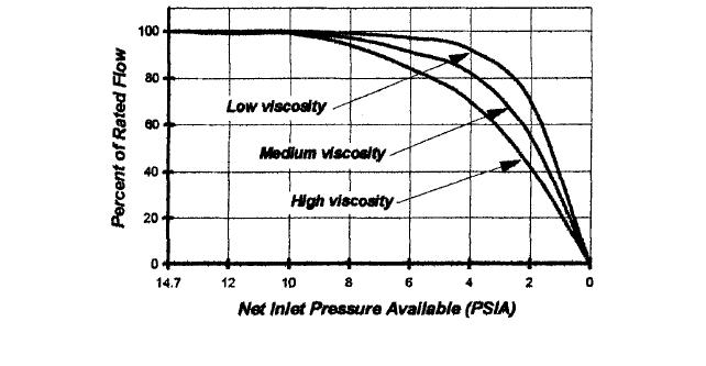
Viscosity Another effect of fluid temperature is on the viscosity of the fluid. For the
majority of the commercial liquids, the viscosity increases with decreasing temperature
and decreases with increasing temperature. If the pump application requires usage over
a wide temperature range, the highest viscosity at this temperature range must be known
to determine whether the pump is operating below the upper speed limit imposed by this
fluid viscosity. The effects of viscosity on speed and the net inlet pressure (above the vapor
pressure of the liquid) required is shown in Figure 12.
Lubricity Still another important fluid characteristic is lubricity. Many rotary pumps
are not designed to operate on liquids with no lubricity. Either the wear rate or the pump
mechanical friction may be inefficiently high if these pumps are used on non-lubricating
fluids.
Cavitation The creation of vapors and the subsequent collapse of the vapor bubbles
upon reaching the higher-pressure discharge side of the pump is known as cavitation.Cav-
itation forces the liquid into the vapor voids at high velocities and produces local pressure
surges of high intensities impinging on the pump surfaces. These forces can exceed the
tensile strength of the metal, eroding it in the process. Left uncorrected, cavitation can
cause pitting of the vanes, gears, or lobes and interior casing walls; bearing failures; and
even shaft breakage. In addition, cavitation causes noise, vibration, and a loss of output
flow. The bigger the pump, the greater the noise and vibration can be.
Lowering the static suction lift of a system, increasing the suction pipe diameter, and
simplifying the suction piping layout can reduce cavitation by raising the net inlet pressure
3.136 CHAPTER THREE
FIGURE 12 How viscosity and net inlet pressure available influence flow (bar = psi/14.5. Expressed as head of
pumped liquid, the net inlet pressure is called NPSH.)
or NPSH available. In reality though, the net inlet pressure available is not something that
can easily be altered. Instead, the pump vendor will usually be asked to select a pump with
a lower net inlet pressure required. The best way to do this is to select a larger pump run-
ning slower. This will give the fluid more residence time to fill the void on the suction side,
and with larger internal passages and ports, pump entry losses will be reduced as well.
Non-Newtonian Fluids The viscosity of most fluids is unaffected by agitation or shear-
ing as long as the temperature remains constant. They are known as true or Newtonian
fluids. Certain fluids, however, change viscosity as a shear is applied at a constant tem-
perature. The viscosity of these fluids will depend upon the shear rate at which it is mea-
sured, and these fluids are termed non-Newtonian. Some examples are cellulose
compounds, glues, greases, paints, starches, slurries, and candy compounds.
If a fluid is non-Newtonian, the viscosity under actual pumping conditions must be
determined and can vary quite a bit from the viscosity under static conditions. An exam-
ple is grease, where the static viscosity is around 20,000 SSU (4300 centistokes). Under
actual pumping conditions, however, the viscosity is closer to 500 SSU (108 centistokes).
Without realizing this, a larger, slower pump may have been offered when a smaller, less
expensive pump running at a higher speed would have been acceptable.
Tests or computations should determine the effective fluid viscosity under actual oper-
ating conditions. If the pump is to operate over a range of speed and pressures, the maxi-
mum and minimum effective viscosities over this range should be known to allow for the
additional slip or horsepower that may be required and to ensure the correct operating
speed and pump driver power selections. If these data are unavailable, as is often the case,
then data from a similar installation can be helpful. Ideally, the information will include
the pump size, flow rate, and speed as well as the NPSH available and the pressure drop
over a specific length of piping. With this information, assumptions can be made regard-
ing the actual viscosity.
Corrosiveness Knowledge of the corrosiveness of the pumped fluid on the pump mate-
rials in contact with the fluid is important to satisfactory pump application. The clear-
ances in rotary pumps are small, and corrosion rates of only a few thousandths of an inch
per year may seriously affect the efficiency of the pump, particularly when it is handling
low-viscosity fluids. In addition, general compatibility of the fluid with the materials of
pump construction must be considered. For example, a certain solvent to be pumped may
soften, dissolve, or destroy the elasticity of flexible members in the pump, including those
flexible members used in the sealing arrangements. Hence, the effect of the pumped fluid
on the physical and chemical state of materials used in pump construction should be con-
sidered when choosing a particular application.
3.8 VANE, GEAR, AND LOBE PUMPS 3.137
Abrasiveness Abrasives present a problem for every pump type, and rotary pumps are
no exception. With small operating clearances, the tendency of the abrasive is to wear
down and open the tight clearances of the pump. Most rotary pumps’ internal clearances
are long, narrow, rectangular cross sections that can be modeled as two parallel flat plates,
with one plate stationary and the other moving. These clearances range from essentially
zero to a few thousandths of an inch. Thus, even minor variations in manufacturing tol-
erances or the effects of wear over time can cause considerable variations in the percent-
age change of the aperture volume. Also, the movement or deflection of movable elements
in the pump, when exposed to pressure differences, can cause relatively large percentage
changes in these clearances in different locations within the pump.
Because rotary pumps depend upon close clearances for their pumping action, when-
ever abrasive or dirty fluids are encountered, accelerated wear can be expected. Wear is
difficult to predict because it depends on many variables that are difficult to measure
(such as particle size, size distribution, or whether smooth or jagged shaped).
Classic theory tells us that laminar slip flow Q
s
between two plates follows the general
equation:
(1)
where Q
s
slip through the clearance, gpm (m
3
/hr)
k a constant
P
d
differential pressure, lb/in
2
(bar)
w width of clearance, in (mm)
d clearance gap or depth, in (mm)
y absolute viscosity, lb-sec/ft
2
(centipoises) [Note: (absolute viscosity in
centipoises) = (kinemetic viscosity in centistokes) sp. gr.]
l length of clearance, in (mm)
Rotary pumps rely on close running clearances to seal between the suction and dis-
charge pressures. This presents certain manufacturing trade-offs. For instance, the clear-
ances must be tight enough to yield an acceptable volumetric efficiency with lower
viscosities, yet large enough to facilitate internal lubrication with higher viscosities. For a
given pump with a fixed viscosity and differential pressure, the slip flow is a function of
the cube of the clearances only.
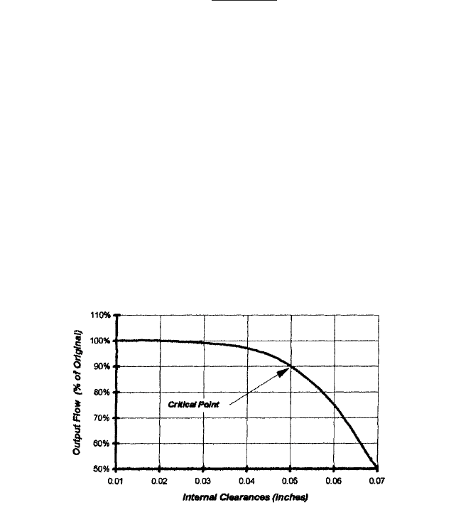
Unlike a centrifugal pump impeller, which can be trimmed to about 85 percent of its
maximum diameter, rotary pump gears, screws, or lobes cannot be trimmed. As Figure 13
shows, up to a certain critical point, wear has little effect on the flow. Beyond this point,
which varies from case to case, performance starts to deteriorate rapidly.
Q
s
k e
P
d
w d
3
v l
f
FIGURE 13 Output flow rate as a function of clearance size and wear
3.138 CHAPTER THREE
Much progress has been made in the use of harder and more abrasive-resistant mate-
rials for the pumping elements. However, rotary pumps should not be used for abrasive flu-
ids, unless a decreased pump life and/or increased maintenance intervals are acceptable.
Other fluid characteristics could be important in the selection and application of vane,
gear, and lobe pumps. Some liquids are sensitive to shear and must be handled in pumps
with low shear rates. Others cannot tolerate exposure to the atmosphere, either because
they can explode, crystallize, and damage the seal arrangement or otherwise interfere
with the pump operation. Rotary pumps for these applications should have only static
seals or multiple-section rotary seals with a protective liquid or gas in the seal zones
between the fluid and outside atmosphere. In aseptic pumps, for example, stationary and
moving seals can be designed with multiple seals to enable the use of steam under pres-
sure as a sterile barrier between the pumping chamber and the atmosphere. Pumps in
industrial applications where it could be dangerous if the fluid were exposed to the
atmosphere may use multiple sealing arrangements with an inert liquid under pressure
acting as a barrier between the pumping chamber and the outside atmosphere.
For the effective application of rotary pumps, the temperature, viscosity, lubricity, cor-
rosiveness, and non-liquid content of the pumped fluid must be known, along with any spe-
cial characteristics of the liquid, such as shear or atmospheric sensitivity. With these
known, the proper pump type, seal arrangements, horsepower requirements, and speed
can be determined.
Vapor Pressure A second effect of fluid temperature is on the vapor pressure of the
fluid. Vapor pressure is the pressure that must be maintained at a given temperature to
prevent the liquid from partially vaporizing into a gaseous state.Vapor pressure increases
with temperature, and if the local pressure falls below the vapor pressure, vaporization
and cavitation will occur.
Vapor pressure is particularly important when handling hydrocarbons and petro-
chemicals, which can have very high vapor pressures. For instance, low-sulfur crude oil
vapor pressures can be as high as 100 lb/in
2
absolute (6.89 absolute) under summer ambi-
ent temperatures. Unless this is known when selecting a pump, the results could be a
pump that works in cold weather but cavitates in warm weather.
OPERATING CHARACTERISTICS _______________________________________
The operating characteristics covered in this section assume the fluid is a true incom-
pressible liquid with a viscosity independent of the rate of shear (shear strain). Common
fluids used in testing are either a light lubricating oil or cool water with small amounts of
soluble oil added for lubricity.
Displacement The theoretical or geometric displacement Q
d
of a rotary pump is the
total gross fluid volume transferred from the OTI volume to the OTO per unit time. A
standard unit of displacement is gallons per minute (cubic meters per hour). For any
given pump, the displacement depends only upon the physical dimensions of the pump
elements and the pump geometry and is independent of other operating conditions. In
those pumps designed for variable displacement, the pump usually is rated at its maxi-
mum displacement.
Slip Flow slip, Q
s
, is an important aspect of rotary pump performance. It is defined as
that quantity of fluid that slips from the OTO volume to the OTI volume per the unit of
time. Slip is a function of the clearances between the rotating and stationary members,
the differential pressure between the OTO volume, the OTI volume, and the fluid vis-
cosity. Hydraulically, it is equivalent to a bypass line from the pump outlet back to the
inlet. The most common unit of measuring slip is U.S. gallons per minute (cubic meters
per hour).
The major slip paths through the pump in the presence of a positive differential pressure
are the clearances between the end faces of the rotors and the endplates of the pump cham-
3.8 VANE, GEAR, AND LOBE PUMPS 3.139
ber, and those between the outer radial surfaces of the rotors and the inner radial surfaces
of the chamber. The width, length, and height of the apertures formed vary considerably
with different positions of the rotor as the drive shaft turns through a complete revolution.
If the differential pressure across the pump remains constant during a revolution, then the
instantaneous slip rate usually varies throughout the revolution. This variation in the slip
is caused by the same effect that would be produced if the physical dimensions of the equiv-
alent bypass around the pump were varied as a function of the angular rotation of the drive
shaft. This is also one of the common causes of flow pulsation in rotary pumps. It is particu-
larly dominant when pumping low-viscosity fluids at high pressures.
The average slip for any set of operating conditions can be found by measuring the flow
rate from the outlet port (assuming an incompressible liquid) and subtracting that flow
rate from the theoretical displacement flow rate Q
d
that would otherwise be expected at
those operating conditions. Most slip paths are constant in width but may vary in height
with runout of the outside diameter of the rotors or wobble of the end faces of the rotors
as they rotate.The paths can also vary considerably in length with the changing positions
of the rotary and body-sealing surfaces during rotation.
The effect of pressure on the slip is complex. The primary effect is direct in that slip
increases in direct proportion to pressure. However, several secondary effects should be
considered as well. The first is the effect of pressure differences across the pump on the
dimensions of the slip path. This occurs because of the deflection of pump elements as a
function of pressure.This is relatively small in rigid element pumps but can be significant
in flexible vane pumps where the pressure can cause the vanes to flatten out and move
away from the body walls. In addition, while the slip may increase in flexible member
pumps at high pressures, in rigid rotor pumps it can actually decrease as clearances close,
due to the high-pressure deflection of the rotors.
Another secondary consideration is the indirect effect of pressure on the fluid velocity
through the slip paths. At any given viscosity, the flow through these paths can have the
characteristics of turbulent, laminar, or slug flows. The majority of practical applications
would require that the slip be a minor percentage of the pump displacement. To remain so,
the velocity of fluid flow through slip paths would normally be in the laminar flow region,
and the slip would then be directly proportional to the pressure difference. A pressure
increase could cause a change to turbulent flow and a corresponding change in the slip as
a function of pressure.
Also, an indirect effect of pressure exists on the effective compression ratio of com-
pressible fluids.The compression ratio reduces the amount of net volume flow through the
outlet port relative to the displacement of the pump. Although not a true slip in the sense
discussed up to this point, the type of slip caused by this effect reduces the net volume
delivered through the outlet port and consequently affects the volumetric efficiency. This
effect is a secondary effect in most liquids but can become a large component of the slip in
aerated or compressible liquids. An increase in the compression ratio caused by an
increase in the pressure difference causes an increase in slip from this effect.
Flow Rate and Displacement The flow rate or capacity Q
c
of a rotary pump is the net
quantity of fluid delivered by the pump per the unit of time through its outlet port or ports
under any given operating condition. When the fluid is incompressible, the flow rate is
numerically equal to the total volume of liquid displaced by the pump per the unit of time
minus the slip, all expressed in the same units. When a rotary pump is operating with
zero slip, the theoretical or geometrical displacement Q
d
of the pump becomes the flow
rate Q
c
. A common unit of flow rate is U.S. gallons per minute (cubic meters per hour):
(2)
The theoretical displacement D per revolution (where Q
d
= ND and N = revolutions per
unit time) can be found by integrating the differential rate of a net volume transfer over
one shaft revolution with respect to the angular displacement of the drive shaft through
any complete planar segment taken through the pump chamber between the inlet and
outlet ports. Most pump rotors have constant radial dimensions in the axial direction in
the body cavity and sweep a right circular cylinder of volume while rotating. This means
Q
c
Q
d
Q
s
3.140 CHAPTER THREE
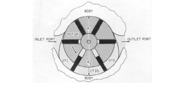
FIGURE 14 Displacement calculation dimensions for an internal vane pump
in single-rotor pumps or in multiple-rotor pumps where no sealing contact exists between
rotors (all dynamic seals are formed between rotor elements and body surfaces), the vol-
ume transfer computation can be based on polar coordinates centered on each rotor axis
and the contribution to the net volume transfer found for each rotor independently.
In general, the axial dimension of the rotor in the body cavity can be most simply
expressed if the planar segment is taken through the rotor axis, or at least parallel to the
rotor axis. Also, for most types of rotary pumps, the computation is simplified if the inter-
sections of the plane with the body cavity occur in a CTIO region, usually midway between
the inlet and outlet ports of the pump.This is particularly true for those rotary pumps that
pump equally well in either direction of rotation and are generally symmetric. In many
cases, the computation can be further simplified by separating the differential statement
for volume transfer through the plane from the inlet to the outlet from that for volume
transfer through the plane from the outlet to the inlet and expressing the results as a dif-
ference. Examples of this method of computation for some commonly used types of rotary
pumps follow.
A section through a vane pump is shown in Figure 14. Let z be the axial distance
toward the front endplate from the rotor end surface next to the rear endplate, and let Z
be the total axial length of the rotor. Let r be the radial distance from the rotor axis. Let
R
1
be the minimum radial dimension of the rotor elements at the intersection of the plane
with the minor cam radius of the pump chamber in the CTIO zone. Let R
2
be the maxi-
mum radial dimension of the rotor elements at the intersection of the plane with the major
cam radius of the pump chamber in the CTIO zone. Let f be the angular displacement of
the drive shaft (assumed to be direct-coupled to the rotor with no gear increase or
decrease). Then, the general equation for D is
(3)
where k is a constant used to convert D to desired units (k 1 if z and r are in feet and D
is in cubic feet per revolution). For vanes with non-zero thickness, the actual value of D
will be slightly smaller than this.
The equation describing the transition of the major radius cam surface to the minor
radius cam surface is not used or needed in Equation 3, because the planar segment is
entirely in the CTIO zone of the pump. Also, the integration limits for r were chosen by
noting that the net volume transfer for all r R
1
cancels and equals zero.The same result
is obtained if the integral is expressed as the difference of the positive contribution of the
integration limits 0 to R
1
.
The same computations and formula apply to flexible vane pumps with the vanes on
the rotor and to any vane-in rotor pump where the surface creating the pumping action is
D
f 2p
f 0
r R
2
r R
1
z Z
z 0
krdfdrdz kpZ1R
2
2
R
1
2
2
3.8 VANE, GEAR, AND LOBE PUMPS 3.141
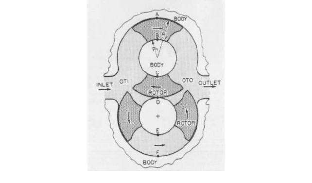
FIGURE 15 Displacement calculations for an external circumferential piston pump
formed on the interior surface of the body chamber. The equation can be used for most
single-rotor positive displacement pumps with an appropriate selection of the numerical
values for R
1
and R
2
. For example, in the vane-in-body pump, R
1
is the minimum radius of
the rotor cam and R
2
is the maximum radius of the rotor cam.
An example extending this method of computing displacement to multiple-rotor pumps
that have no rotor-to-rotor sealing contact is the computation on the external circumfer-
ential piston pump shown in Figure 15. A derivation can be made in the same manner
used for the vane pump, and the individual equations for the net volume flow for each
rotor can be computed and summed.
The pump in Figure 15 is symmetrical, and the net contribution of each rotor occurs
only during a total of half of the drive shaft revolution. In the derivation shown in Equa-
tion 3, this would mean a change in the integration limits of f from 2p to p for the con-
tribution of each rotor. However, when the contributions from each of the two rotors are
added, the result is the same as Equation 3.
Another method could also be used. Because of the pump symmetry, an inspection
shows that two net volume components are continually transferred from the inlet to the
outlet chamber by the motion of the rotors in zones A–B and E–F. One equal volume ele-
ment is also continually transferred from the outlet to the inlet chamber of the cooperative
action of the rotors in zone C–D. Consequently, the net volume being transferred from the
outlet to inlet in zone C–D is continually canceled by one of the volumes continually being
transferred from the inlet to outlet at either zone A–B or zone E–F. The entire computa-
tion then can be made only for zone A–B or zone E–F over the entire revolution.The result-
ing formula for displacement would be that given in Equation 3, with R
1
being the
minimum radial dimension of the piston element of the rotor and R
2
being the maximum
radial dimension of the piston element of the rotor.
The direct computation of displacement for multiple-rotor, positive displacement pumps
where a moving seal is formed by contact between rotors is much more complex. In such
pumps, the equation of motion of the locus of the contact point between rotors as a function
of angular displacement of the drive shaft is needed for a rigorous solution of the displace-
ment. The differential rate of volume transfer is not constant with angular displacement
but decreases as the contact locus moves toward the inlet chamber and increases as the
contact locus moves toward the outlet chamber. In this case, a graph of pump displacement
versus angular displacement would not be a straight line (or constant function of angular
displacement), as in the prior two examples. In effect, the motion of the contact locus super-
imposes a ripple on the steady-state component of the differential rate of volume transfer.
3.142 CHAPTER THREE
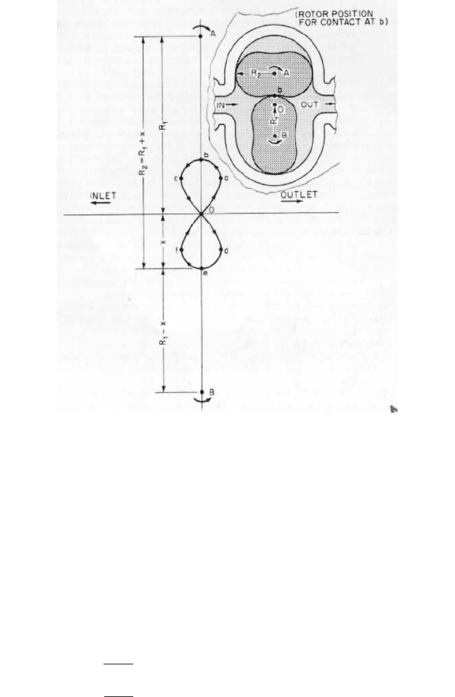
FIGURE 16 Rotor contact locus of lobe pump
Figure 16 shows the locus of the contact line between lobes in a two-lobe pump. The
locus is shown on a plane taken perpendicular to the planar segment used for computing
displacement, which is taken through the axis of both rotors with the center of rotation of
the two rotors being points A and B. Point O is midway between the two rotor centers.The
lower-case letters represent essential points in the differential rate of volume transfer.
Remembering that velocity of the movement of the locus point toward or away from the
outlet port determines the amount of plus or minus deviation from the average differen-
tial transfer rate, the following observations can be made.
The maximum instantaneous differential volume transfer rate occurs as the locus
passes through point O on its way from c to d or from f to a. The minimum instantaneous
rate of differential transfer occurs when the locus passes through point b or point e. The
average differential rate of transfer occurs at points a, c, d, and f. In the symmetric case
shown, if R
1
is the distance from O to A or B, if x is the distance from O to b or e, and if
R
2
is the maximum radial dimension of a lobe, then derivations similar to those given
before will give the maximum and minimum differential rates of volume transfer:
(4)
since, for the lobe pump shown, R
2
R
1
x.
dD
df
min
1kZ1R
2
2
R
1
2
x
2
2 kZ321R
2
R
1
R
1
2
24
dD
df
max
kZ1R
2
2
R
1
2
2

3.8 VANE, GEAR, AND LOBE PUMPS 3.143
In most pumps of practical design, the peak-to-peak amplitude of the ripple is less than
10 percent of the steady-state component of displacement. Consequently, computing the
peak displacement (where R
2
is the maximum radial dimension of the rotor and R
1
is half
the distance between rotors of equal size) can approximate the displacement for multiple-
rotor pumps with contacting rotors. The equation is given as
(5)
If the rotors are of unequal size, the transfer rate must be computed for each rotor with
R
1
taken as the radius of the pitch circle of the rotor. This also applies to gear pumps where
R
1
is the radius of the pitch circle of the gears. Displacement computed by this simplified
method will usually be within five percent of the true average displacement for lobe
pumps and within one percent for gear pumps. For a closer approximation, Equation 5 can
be used. It is precise only when the ripple waveform has a zero average component and
when it is symmetric.
From a practical standpoint, pump displacement often cannot be computed precisely
from the geometry of the pump and is instead established by testing. In either case, the
manufacturer will usually state this because it is needed to determine the efficiency of the
pump under various operating conditions.
Speed Considerations Centrifugal pumps typically run at synchronous motor speeds.
The flow and head are fine-tuned by such things as trimming the impeller or underfiling
the impeller vanes. Rotary pumps, on the other hand, operate with their internal dimen-
sions fixed. Performance is usually fine-tuned externally by speed adjustments where the
operating speed N is the number of revolutions of the driving or main rotor per unit time.
When no gear reduction or increase exists between the drive shaft and the main rotor, the
speed is measured or set at the drive shaft.
The most common unit of speed is rpm, and its direction is usually described as either
clockwise or counterclockwise when viewed from the front or drive end of the pump looking
at the pump shaft. The economy of manufacturing, special pressure-balancing arrange-
ments, relief valve orientations, and other such considerations have led to some pump
designs requiring that the pump operate in one direction only. However, most rotary pumps
will operate equally well in either direction.
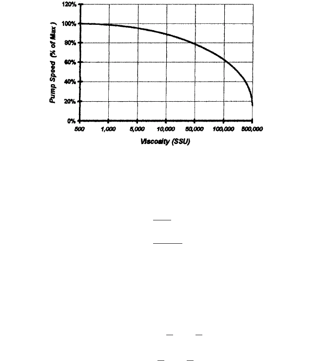
Usually, no minimum speed exists for a rotary pump, but certain vane pumps that
depend on a centrifugal force to draw the vanes out of their slots do have minimum speed
requirements. Another exception is with low-viscosity fluids at high pressures where the
slow speed enables slip to equal the theoretical displacement, resulting in no net output
flow. To avoid this situation and assure the pump is running at a suitable volumetric effi-
ciency, the pump should always run within its permitted speed range. Figure 17 shows a
typical speed versus viscosity curve for a rotary pump.
Since flow is directly proportional to speed, it can be tempting to increase the pump
speed above its maximum speed to obtain more flow. However, besides all the aforemen-
tioned concerns, one other item must be considered. With any rotary pump, as the cavities
rotate, they present a void for the incoming fluid to fill. This void is available for a fixed
amount of time, and the fluid in the suction chamber must accelerate to fill this void in the
available time.The higher the fluid viscosity, the more energy is required to accelerate the
fluid to fill the void. If the fluid cannot fill the void in the time available, a partial void and
cavitation will occur.
Pressure The absolute pressure of the fluid at any location in the pump, expressed in
lb/in
2
(bar), is the total pressure there and the basis for all other pressure definitions asso-
ciated with pump operation. Helping to simplify matters, the velocity pressure P
vel
com-
ponent of the fluid is usually small enough relative to the total pressure to be neglected.
D
max
2pkZ1R
2
2
R
2
1
2
D
min
4pkZ1R
2
R
1
R
1
2
2
D
av
2pkZ a
R
2
2
2
R
2
R
1
3
2
R
1
2
b
3.144 CHAPTER THREE
FIGURE 17 Typical speed reduction as a function of viscosity (In this range, centistokes = SSU/4.6)
In addition, where the fluid velocities (at the same pump locations used to determine the
pressure differences) are sufficiently alike, they will cancel each other out. Should this not
be so, velocity or dynamic pressure P
vel
can be computed as
in USCS units (6)
in SI units
where P
vel
dynamic pressure of the fluid being pumped
w fluid specific weight (mass), lb/ft
3
(kg/m
3
)
V fluid velocity, ft/s (m/s)
g acceleration due to gravity, ft/s
2
(m/s
2
)
or can alternately be expressed as
in USCS units (7)
in SI units
where Q flow, gpm (m
3
/min)
a cross-sectional area perpendicular to flow, in
2
(mm
2
)
Several pressure terms are of interest. The outlet or discharge pressure P
o
is the total
pressure at the outlet of the pump. In pumps with multiple outlets, this pressure is usu-
ally defined at the location in the outlet manifold where the pump is mated to the exter-
nal piping system. Although composed of the sum of system and velocity pressures
external to the pump, the outlet pressure is most commonly expressed as the gage pres-
sure at the outlet port. The gage pressure (lb/in
2
gage or bar) is the difference between the
absolute pressure and atmospheric pressure at the point of measurement.
The inlet or suction pressure P
in
is the total pressure at the inlet to the pump or, for
multiple-inlet pumps, at the manifold location where the pump connects to the external
piping system. In common practice, the inlet pressure can be variously expressed as
absolute pressure (lb/in
2
absolute or bar), as positive or negative gage pressure (lb/in
2
gage
or bar), or as vacuum (inches or millimeters of mercury).
P
vel
13,600 a
w
g
b a
Q
a
b
2
P
vel
0.000357 a
w
g
b a
Q
a
b
2
P
vel
wV
2
20,387g
P
vel
wV
2
288g