Puigjaner L. (ed.) Syngas from Waste - Emerging Technologies
Подождите немного. Документ загружается.


run at the desired plant conditions and model outputs are compared, while for the
other type of comparisons typically a sensitivity analysis is performed.
Also the accuracy of the model is checked in terms of the net power,
by-products and clean gas characteristics, as shown in Table 4. Measured data
come from ELCOGAS power plant.
The biggest discrepancy is in the estimation of the ASU consumption and in the
amount of sulphur recovery, which is overestimated. It can be deduced that the
underestimation of the LHV of the clean gas is compensated in the CC with a
bigger efficiency. Nevertheless, by considering the results as a whole, it can be said
Table 2 Technical data for the IGCC plant model
Gasification
Feedstock 2,600 tons day
-1
Crusher fineness 50–60 lm
Feedstock MC 2%
P of lock hoppers 30 bars
T
gasif
1,400–1,500C
P
gasif
25 bars
O
2
/O
2
stoich (mole basis) Raw material dependant
H
2
O/C
in
(mass basis) Raw material dependant
T before the WHB 850C
T before gas cleaning 235C
Max. P before CC 3 bars
Combined cycle (CC)
Air
in
Conditioned by gasifier and gas turbine cycle
requirements
HP/IP/LP 127/35/6.5 bars
HP/IP/LP T before ST 510/520/265C
Compressor pressure ratio 15.7
T
cg
before combustor 300C
TOT 540C
P of the saturation column 20.8 bars
T of the flue gas 100C
T of the air to air separation unit
(ASU)
130C
Consumables
NaOH (15 mass%) Syngas and cleaning water dependant
H
2
SO
4
(96 mass%) Cleaning water dependant
Natural gas Feedstock dependant
H
2
O Syngas and raw material dependant
CH
3
OH Proportional to the amount of CO
2
in the shifted gas
Air separation unit (ASU)
Oxygen purity 85% volume basis
Radiation losses 2% adiabatic reactor
T
o
15C
P
o
0.9309 bars
188 A. D. Bojarski et al.

that in a conceptual stage this modelling approach represents an accurate enough
approximation of an IGCC power plant, with an error in the range of preliminary
design, where error within 15–20% are acceptable [39].
Many different metrics can be defined to prove the validity of the IGCC overall
model checking model tendencies. Some of them are the raw gas composition or
the LHV; others such as cold gas efficiency (CGE, defined in Eq. 31 of chapter
‘‘ Modelling Syngas Generation’’), or the Eff
CCapture
(defined in Eq. 28 of chapter
‘‘ Main Purification Operations’’ and revised here as well in Eq. 11) previously
defined, are also used. The following paragraphs define other efficiency terms
usually referred.
The energy efficiency of the combined cycle (Eff
CC
) is defined as the ratio
between the net power of the CC (considering the energy consumed by the
Table 3 Modelled units in Aspen Plus
Block Aspen Plus model
Feedstock dust
preparation
Dust preparation: crusher
Combustion chamber: Gibbs reactor
Dryer: stoichiometric reactor
Bag filters: two phase (VL) flash separator
Lock hopper: mixer
Gasification and WHB Gasifier: yield and Gibbs reactors
Solid removal: component splitter
WHB: heating units and a compressor for gas recycling
Syngas cleaning Venturi scrubber: RadFrac column and two-phase (VL) flash separator
Sour water stripper: RadFrac columns
COS hydrolyser: stoichiometric reactor
MDEA absorber: RadFrac columns
Claus plant: stoichiometric and Gibbs reactors and two-phase (VL) flash
separators
WGS reactor: two equilibrium reactors
Rectisol process: RadFrac columns
PSA unit: Component splitter
Liquefactor: flash separator and compressor
CC and HRSG Turbines, compressors and heating units Combustor: Gibbs reactor
Saturator: two-phase (VL) flash separator
HRSG: heating units
ASU Compressors and heating units, and component splitter
Table 4 Overall IGCC plant
validation data
Measured Model Error %
Raw gas flow (kg h
-1
) 202,500 192,272 -5.05
LHV clean gas (kJ kg
-1
) 9,911 9,547 -3.68
Gross power (MW) 308 315 2.27
ASU consumption (MW) 29 27.4 -5.52
Net power (MW) 283 285 0.71
Sulfur (kg h
-1
) 3,113 3,318 6.59
Modelling Superstructure for Conceptual Design 189

compressor), and the total chemical energy contained in the clean gas (cg) which is
fed to the gas turbine, see Eq. 6. Even if the most usual stream is clean gas,
hydrogen or PSA purge gas can also be fed to the GT. Note that even if Eq. 6
refers it as cg, depending on the scenario characteristics, the denominator can have
either of the abovementioned natures.
Eff
CC
¼
Power
net
m
cg
LHV
cg
ð6Þ
By considering the plant as a whole, the total profitable energy that goes into
the system is related with the final electricity to the grid. This energy efficiency
(Eff
global
) is calculated as in Eq. 7.
Eff
global
¼
Power
net
m
feed
LHV
feed
ð7Þ
In an analogous way, in the case of H
2
production, the global efficiency is
calculated as in Eq. 8.
Eff
global
H
2
¼
m
H
2
LHV
H
2
m
feed
LHV
feed
ð8Þ
Equation 31 of chapter ‘‘Modelling Syngas Generation’’ and (6) evaluate the
performance of the gasifier and of the CC separately, while the Eff
global
provides a
metric of the overall installation. In order to relate the former definitions the
efficiency associated to the gas cleaning operations (Eff
cl
) can be defined as in
Eq. 9, where m
rg
and m
cg
refer to the raw and clean gas mass flows.
Eff
cl
¼
m
rg
LHV
rg
m
cg
LHV
cg
ð9Þ
Consequently, Eff
global
can be calculated from the partial efficiencies as in
Eq. 10.
Eff
global
¼ Eff
CC
Eff
cl
CGE ð10Þ
In an analogous way, for the H
2
production the global efficiency can be cal-
culated by considering in this case the partial efficiencies, including the efficiency
of the carbon capture train (Eff
CCapture
), where this is defined last as in Eq. 12.
Eff
CCapture
¼
m
H
2
LHV
H
2
m
cg
LHV
cg
ð11Þ
Eff
global
H
2
¼ Eff
CCapture
Eff
cl
CGE ð12Þ
The validation of model trends is done by computing the former metrics, by
means of sensitivity analysis (SA). In every SA the LHV of each stream, raw gas
mole flowrates, emissions, by-products, power and water consumption are con-
sidered and taken directly from model results. While the LHV of fuels is calculated
190 A. D. Bojarski et al.

using Eq. 32 in chapter ‘‘Modelling Syngas Generation’’, the estimation of LHV
rg
and LHV
cg
is performed using the Aspen Plus
property sets (QVALNET) [20].
Differences between each case study lie on raw material composition, and they
consider the oxygen ratios to the gasifier and to the combustion chamber in the CC
with an adjustment of the gasifier temperature (T
gasif
), to remain close to the
1,400C and the TOT, to be as close as possible to 540C.
The sensitivity analysis (SA) performed changes considering the gasifier
feedstocks: the equivalence ratio, ER, is changed in an interval of ±30% its base
case value (i.e., a variation from 0.29 to 0.55), while the steam ratio is varied
between 0.15 and 0.4 for all case studies. To point out that due to the oxygen ratio
value into each case study, the ratio, defined as proportionate to the stoichiometric
oxygen of the mixture, is always below the complete combustion value. Eight
values are considered in both ranges; accordingly 64 points are resulted for each
analysis. The CC fed oxygen ratio is maintained constant.
The SA results are represented in two-dimensional graphs, where the axis
corresponds to the input variables and the output variable changes are plotted using
contour lines. Blue points in the graphs are the SAs results, while the red star point
is the highest value, for the output variable in the SA.
ER
H
2
O ratio
T
gasif
0.3 0.35 0.4 0.45 0.5 0.55
0.15
0.2
0.25
0.3
0.35
0.4
800
1000
1200
1400
1600
1800
2000
2200
2400
ER
H
2
O ratio
TOT
0.3 0.35 0.4 0.45 0.5 0.55
0.15
0.2
0.25
0.3
0.35
0.4
490
500
510
520
530
540
550
ER
H
2
O ratio
LHV
rg
0.3 0.35 0.4 0.45 0.5 0.55
0.15
0.2
0.25
0.3
0.35
0.4
7
8
9
10
11
12
x 10
6
Fig. 8 Iso-lines for T
gasif
, TOT, and LHV
rg
in C and J/kg, respectively, for the base case
Modelling Superstructure for Conceptual Design 191

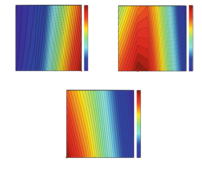
Figure 8 reports the variation observed for T
gasif
, TOT and the LHV
rg
.Itis
clearly seen that in the role as a moderator of the steam in the gasifier higher steam
ratios are followed by lower temperatures, and that more inlet oxygen implies
higher temperatures.
The considered SA leads to gasification temperatures in the range of 800–
2,400C, even if the gasification zone is in the middle, limited by CH
4
and sulphur
oxides production. TOT is between 550 and 490C. In the modelled installation
and regarding the HRSG, lower temperatures than 540C are not feasible operating
regions due to the steam temperature requirements. With regard to the LHV
rg
,it
can be seen that the highest values are obtained for the combination of lowest H
2
O
and ER.
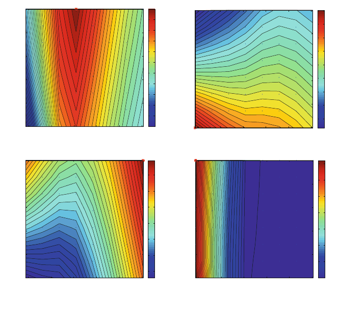
Syngas compositions (H
2
, CO, CO
2
and CH
4
) are represented in Fig. 9. In the
case of CH
4
its occurrence is mainly driven for the O
2
amount coupled with high
gasifier temperatures (see Fig. 8 left, and Fig. 9 bottom right). For the case of H
2
,
CO and CO
2
non-linear shapes are found. In the case of H
2
, the highest H
2
production is found for an ER close to 0.4, and for the highest ratio of steam fed,
ER
H
2
O ratioH
2
O ratio
H
2
O ratioH
2
O ratio
Mole H
2
0.3 0.35 0.4 0.45 0.5 0.55
0.15
0.2
0.25
0.3
0.35
0.4
4
6
8
10
12
14
16
18
20
22
24
ER
Mole CO
0.3 0.35 0.4 0.45 0.5 0.55
0.15
0.2
0.25
0.3
0.35
0.4
50
52
54
56
58
60
62
64
66
ER
Mole CO
2
0.3 0.35 0.4 0.45 0.5 0.55
0.15
0.2
0.25
0.3
0.35
0.4
2
4
6
8
10
12
14
ER
Mole CH
4
0.3 0.35 0.4 0.45 0.5 0.55
0.15
0.2
0.25
0.3
0.35
0.4
0
2
4
6
8
10
12
14
Fig. 9 Iso-lines representing the molar fraction (%) of raw gas components in dry basis for the
base case
192 A. D. Bojarski et al.

which is in clear concordance with Eqs. 22 and 23 in chapter ‘‘Modelling Syngas
Generation’’. In the case of CO
2
, a clear relationship with H
2
composition is found
but its highest values are found for the maximum amount of O
2
and steam. As
expected, the CO behaviour is opposite to the one obtained for CO
2
.
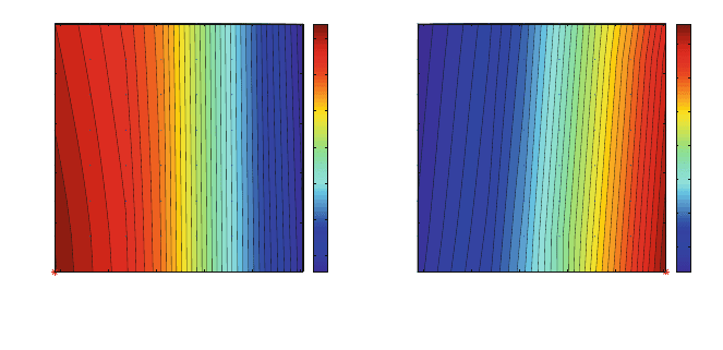
Figures 10 and 11 are highly interrelated; firstly, steam and gas turbines power
production are shown in Fig. 10. The amount of power produced by the gas turbine
reaches a maximum when ER and steam ratio are the lowest. On the contrary,
steam turbine production is maximum at higher oxygen ratios but minimum at
lower steam ratios. In both cases the influence of O
2
ratio is more important than
the one of steam ratio.
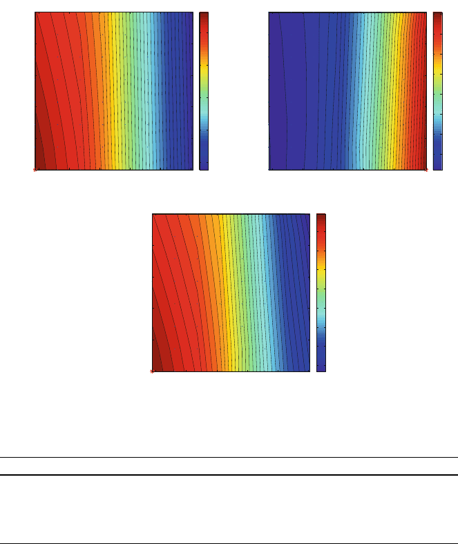
In the case of CGE, it is found in Fig. 11 (top left) that the highest value
coincides with the one obtained for the maximum gas turbine power production,
and is in concordance with the higher LHV
rg
values found in Fig. 8, given that the
fuel LHV remains constant. Similarly, the Eff
global
shows the same behaviour due
to the fact that most of power comes from GT, and the fact that fuel LHV remains
constant. In the case of the highest value for Eff
CC
, it coincides with the highest
steam turbine power production, therefore with highest gasification temperatures
the WHB recovers more heat for steam production.
It is demonstrated here that oxygen ratio has higher influence in gasification
than the steam one. The CGE is the main parameter that influences in the final
global efficiency of the plant, since it is the GT that produces more power.
3.5 Results
Let us compare the base case, where all the syngas goes to the CC, with the
extreme cases where all the clean gas is used to produce: (a) pure H
2
to be sold to
the market, (b) pure H
2
to be sold to the market with PSA purge gas used in the CC
or (c) H
2
to be used in a hydrogen turbine in a CC. The main difference between
ER
GT
0.3 0.35 0.4 0.45 0.5 0.55
0.15
0.2
0.25
0.3
0.35
0.4
170
180
190
200
210
220
230
ER
H
2
O ratio
H
2
O ratio
ST
0.3 0.35 0.4 0.45 0.5 0.55
0.15
0.2
0.25
0.3
0.35
0.4
80
85
90
95
100
105
110
Fig. 10 Iso-lines for gas and steam cycles power production (MW) for the base case
Modelling Superstructure for Conceptual Design 193

the (a) and (b) with the (c) scenarios is the use or not of the PSA unit, since if the
H
2
is not going to the market, its required purity is not restrictive. Moreover, in all
cases the Rectisol block is used to separate H
2
from the remaining gases, which
could be profited by a carbon capture scheme, and it is not profited in the GT.
The main advantage of using H
2
in GT combustion is the lesser level of
emissions to the atmosphere, which hypothetically will involve only water. In
these cases, we are assuming that the GT conceived for syngas (operating and
main characteristics) can be used for H
2
. Please note that this requires the HRSG
structure to be defined for generating steam from GT flue gas works similarly
when being fed with steam from H
2
combustion. See in Table 5 the most
Table 5 Comparison between electricity and H
2
production
Syngas to CC H
2
to market H
2
to market - PSA to CC H
2
to CC
Eff
global
(%) 42 – 5.4 33.3
Eff
global
H
2
(%) – 51 51 –
Gross power MW 315 0 85 273
Net power MW 285 -46 37 226
ER
CGE
0.3 0.35 0.4 0.45 0.5 0.55
0.15
0.2
0.25
0.3
0.35
0.4
60
65
70
75
80
ER
H
2
O ratio
H
2
O ratio
H
2
O ratio
Eff
cc
0.3 0.35 0.4 0.45 0.5 0.55
0.15
0.2
0.25
0.3
0.35
0.4
54
55
56
57
58
59
60
61
ER
Eff
global
0.3 0.35 0.4 0.45 0.5 0.55
0.15
0.2
0.25
0.3
0.35
0.4
35
36
37
38
39
40
41
42
Fig. 11 Iso-lines for unitary and global efficiencies (%) for the base case
194 A. D. Bojarski et al.
important parameters reported for each case study: the efficiency calculated as in
Eqs. 7 and 8 depending on the final output, and the gross and net power for each
situation. Note that even if the compressor in the GT cycle is not working for the
GT itself, it is needed to compress the air that goes to the ASU.
The first column corresponds to the base case where all syngas is combusted in
the CC. The other columns correspond to the following scenarios that imply
several changes in the flowsheet layout. In all the scenarios performed, the amount
of air that goes to the GT is regulated with a design specification in Aspen Plus
in
order to adjust TOT to a temperature around the 540C:
• H
2
to market: In this scenario, the HRSG has been deactivated. We are
assuming that no air for the GT combustor is entering the system, and that no
refrigeration is needed for the turbine. The waste N
2
from the ASU can be sent
to the feeding system, since it is not needed in the GT system.
• H
2
to market–PSA to CC: It is similar to the previous one. In this case, an
amount of ‘‘residual’’ power is produced. It checks the validity of this PSA
residual gas as feed for the gas turbine, but it does not justify the presence of a
turbine, as seen in Table 5. The HRSG is again activated, as well as the
refrigeration system of the gas turbine.
• H
2
to CC: In this scenario, as this differs from the two previous ones, the PSA
unit is not used; thus, the hydrogen produced in the WGS reactors is directly
sent to the CC.
Table 5 shows that the efficiency penalty of a combined cycle with syngas or
with H
2
is around 7%. This is due to the extra power consumption of the carbon
removal train, to obtain the final H
2
stream. On the other hand, the increase of
feedstock that would supply the same amount of power in a CC moved by
hydrogen instead of syngas, according to this data is about 21%.
Analogous to chapter ‘‘Main Purification Operations’’, the outputs of the
superstructure (power and H
2
calorific value) have been analysed versus the per-
centage of syngas stream that goes to the CC. The electricity consumed by the
carbon capture technology has been considered. In the case of H
2
production, the
consideration here is the production of pure H
2
to be sold in the market. It is
interesting to appreciate that at the value of 50%, the calorific value of the H
2
is the
same than the gross power produced by the CC, thus deducing that both appli-
cations have similar efficiencies. Figure 12 shows the lineal dependencies of the
abovementioned parameters. It is interesting to mention that the production of
hydrogen has an almost constant efficiency of 68% in all the scenarios. In the case
of the gross power, two different behaviours have been plotted: in dashed black the
one that considers all waste N
2
available from the ASU being fed to the combustor
of the GT, and in colour the one considering a fraction of the waste N
2
stream
being separated according to the same fraction that of syngas. This waste N
2
stream has a flowrate of 246,000 kg h
-1
and a temperature of 384C at a pressure
of 20 bars, and in general is profited to increase the GT overall flowrate, while the
syngas is fed to the GT at 147C. The efficiency of the CC is different in the former
two situations: in the first one, the efficiency increases while the proportion of
Modelling Superstructure for Conceptual Design 195

syngas to the CC decreases, ranging from 63 to 71% for values of the splitter
between 1 and 0.4. In the second situation the efficiency is approximately constant
around the 63%. It is due to the importance of the total flowrate that goes to the
GT, which is crucial for the final power produced. See Fig. 13 where the effi-
ciencies comparison is plotted.
In both Figs. 12 and 13, note that the lines related with the CC operation are not
plotted for all the split fractions, given that there is a operative limitation of
reaching a TOT value around 540C, in order to make the GT work properly. It is
found that for some split fraction scenarios it is impossible to obtain a value of
TOT close to its requirement, even with the stoichiometric combustion of the
syngas. This means that there is a certain amount of waste N
2
that refrigerates the
combustion mixture too much, which can also be interpreted that the combustion
mixture does not have the appropriate flowrate to produce the high temperature
gases adequate for the GT operation. Note that the gross power produced with
-20
60
140
220
300
380
0 20406080100
MW
% Syngas to CC
Gross Power H2 C Capture
H
2
Fig. 12 H
2
, carbon capture
technology consumption and
gross power variation with
the percentage of syngas that
goes to the CC. In colour,
again the gross power but
with waste N
2
separation
50
55
60
65
70
75
80
020406080100
%
EffCC EffCCN2 Effccapture
% Syngas to CC
Fig. 13 Efficiencies for the
CC and the carbon capture
sections. Eff
CCN2
contemplates N
2
separation
196 A. D. Bojarski et al.
waste N
2
constant is higher than the one that separates it, even if this last option
allows for an operation with a smaller amount of syngas.
4 Conclusion
This chapter has provided an overall view of the possible ways of handling the
IGCC design problem from a flowsheet optimisation point of view (preliminary
design). Clearly, it has shown the importance of the notion of superstructure,
which is introduced in the first section. It provides the necessary flexibility and
versatility in the selection of the best alternative design during the synthesis
procedure. Moreover, different algorithms introduced for tackling the design
optimisation are readily accessed by the superstructure. Model validation is
emphasised by means of plant data comparison and by the use of sensitivity
analysis. Finally, the efficiency penalty because of CO
2
capture methods is dem-
onstrated through four case studies. The limitation in poly-generation associated to
the value of TOT in the flue gas stream is analysed in depth. In this sense the
superstructure and its versatility have been proved and ready for scenarios
optimisation.
References
1. Cameron I (2005) Modelling across the process life cycle: a risk management perspective.
Eur Symp Comput Aided Process Eng 15:3–19
2. ISO15288 (2008) Systems and software engineering—system life cycle processes. Technical
report ISO, Genève, Switzerland
3. ISO14040 (1997) Environmental management—life cycle assessment—principles and
framework. Technical report ISO. Genève, Switzerland
4. Cameron IT, Newell RB (2006) Modeling in the process life cycle. In: Puigjaner L, Heyen G
(eds) Computer aided process and product engineering, Sect. 4.2. Wiley, New York, pp 667–
693
5. Yang Y, Shi L (2000) Integrating environmental impact minimization into conceptual
chemical process design: a process systems engineering review. Comput Chem Eng 24:1409–
1419
6. Rebitzer G, Ekvall T, Frischknecht R, Hunkeler D, Norris G, Rydberg G, Schmidt W, Suh S,
Weidema B, Pennington D (2004) Life cycle assessment Part 1: framework, goal and scope
definition, inventory analysis, and applications. Environ Int 30:701–720
7. Douglas JA (1985) Hierarchical decision procedure for process synthesis. AlChE J 31:353–
362
8. Biegler L, Grossmann I, Westerberg A (1997) Systematic methods of chemical process
design. Prentice-Hall, Englewood Cliffs
9. Yeomans H, Grossmann IE (1999) A systematic modeling framework of superstructure
optimization in process synthesis. Comput Chem Eng 23:709–731
10. Metz B, Davidson O, Coninck H, Loos M, Meyer L (2005) Special report on carbon dioxide
capture and storage, Chap. 3. IPCC, Switzerland
Modelling Superstructure for Conceptual Design 197
