Protection Application Handbook (англ. яз.)
Подождите немного. Документ загружается.


POLE DISCORDANCE RELAYS
Bus&Breaker Protection
for worldwide cooperation
201
BA THS / BU Transmission Systems and Substations
LEC Support Programme
Pole discordance relay “PD” is necessary to prevent service with
only one or two phases of a circuit breaker closed. This will cause
an unsymmetry that can lead to damage of other apparatus in the
network. Unsymmetrical conditions can only be accepted during
a single pole Auto reclosing cycle.
When single pole Auto reclosing is used a blocking of the PD is
necessary during the single phase dead time, see figure 9.
The timing sequence at closing and opening of breakers and the
timing of the operation at a pole discrepancy tripping must be
checked carefully. It is e. g. often necessary to operate the flag
relay first and the tripping from this relay to achieve correct indi-
cation at a trip as the main contacts will rather fast take away the
actuating quantity when the remaining poles are opened.
Tripping from PD should be routed to other trip coil than the one
used by manual opening. This is due to the fact that at manual
opening there could be an incipient fault in the circuit. This incip-
ient fault could result in that only one or two phases operate and
the MCB for the circuit is tripped. PD would thus not be able to
operate if connected to the same coil as manual opening.
Operation of PD shall in addition to tripping the own circuit break-
er start Circuit Breaker failure relay, lock-out the own circuit
breaker and give an alarm.
A normal time delay for a PD relay should be approximately
150-200 ms when blocking during single pole Auto reclose is per-
formed. If not the necessary time is about 1,2 sec.
Note
: Some customers do not rely only on the auxiliary contacts
and want to detect Pole discordance also by measuring the resid-
ual current through the breaker at breaker for some second at
opening and closing.
We have however good experience of the contact based principle
and recommend only this simple principle.
Residual current measurement at closing and opening is not a re-
liable function either as there is no load current when a line is
closed from one end only and on the other hand normal residual

POLE DISCORDANCE RELAYS
202
BA THS / BU Transmission Systems and Substations
LEC Support Programme
currents can occur if the closing is onto a fault or e. g. energizes
a transformer at the far end of the system.
Conclusion is to use a simple contact based Pole Discordance
function which is simple and reliable. The residual current based
principle is more complicated and can give difficulties in setting
of sensitivity etc.

INTRODUCTION
Earth Fault Protection
for worldwide cooperation
203
BA THS / BU Transmission Systems and Substations
LEC Support Programme
1. INTRODUCTION
The fault statistic shows that earth faults are the dominating fault
type and therefor the earth fault protection is of main importance
in a network.
The type of earth fault protection used is dependent of the sys-
tem earthing principle used. In the following the earth fault pro-
tection for solidly- (effectively), reactance-, high resistive- and
resonance earthed systems are covered.
2. EFFECTIVELY EARTHED SYSTEMS
In the effectively earthed systems all transformers are normally
connected to earth and will thus feed earth fault current to the
fault. The contribution from all earthing locations gives special re-
quirements for the protection system.
2.1 FAULT RESISTANCE AND FAULT
CURRENT LEVELS
In order to calculate fault currents in an effectively earthed sys-
tem we must use the representation with symmetrical compo-
nents.
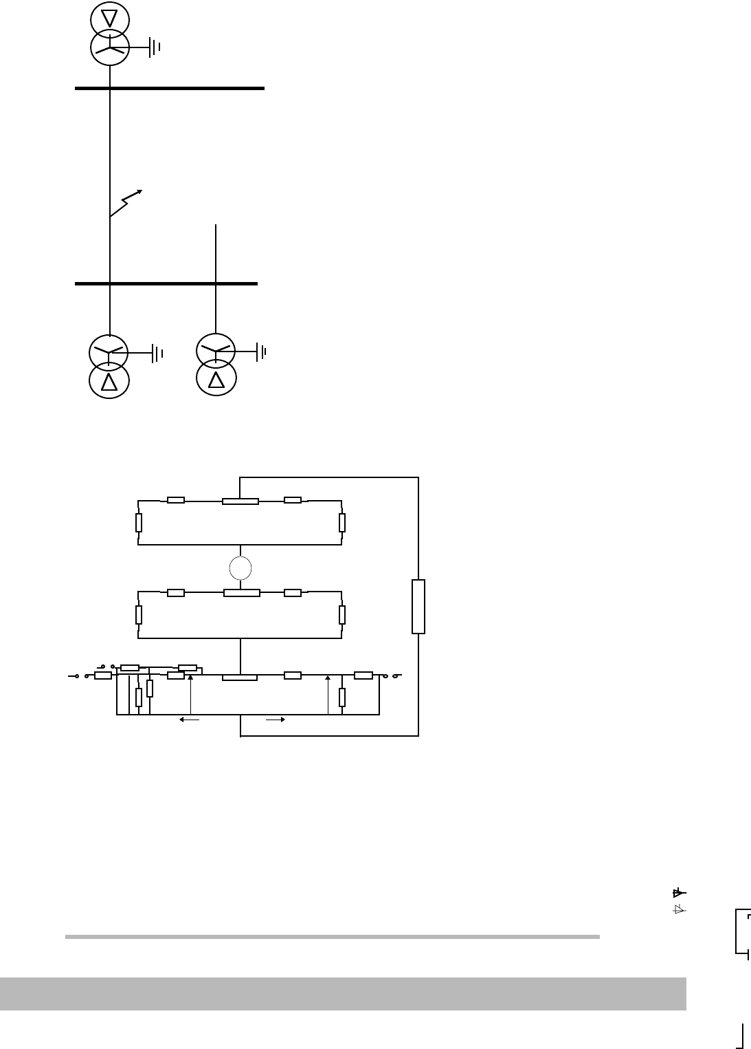
The symmetrical component scheme for a 132 kV system with a
fault according to Figure 1 is shown in Figure 2.

EFFECTIVELY EARTHED SYSTEMS
204
BA THS / BU Transmission Systems and Substations
LEC Support Programme
.
Figure 1. An earth fault in a direct, effectively earthed system.
Figure 2. The symmetrical components are used to calculate the “I
0
” current
for the fault in figure 1, “3I
0
” is the total fault current.
The distribution of fault currents, from the different system earth-
ing points, can be derived from the distribution in the zero se-
quence network (see figure 2). By inserting varying fault
resistances one can get the fault current level.
3R
f
Positive sequence
Negative sequence
Zero sequence
Uh/√3
I01
U0
U0
I02

EFFECTIVELY EARTHED SYSTEMS
Earth Fault Protection
for worldwide cooperation
205
BA THS / BU Transmission Systems and Substations
LEC Support Programme
The fault resistance “R
f
”, consists of the arc resistance and the
tower foot resistance. The arc resistance is calculated by the for-
mula:
R
arc
= 28700a / I
f
1.4
(according to Warrington)
where “a”, is the arc length in meter, normally the insulator length,
and “I
f
” is the fault current in “A”.
A calculation will show that values will differs from below 1 Ω for
heavy faults, up to 50-400 Ω for high resistive earth faults.
The tower foot resistance depends on the earthing effectiveness
of the towers, whether top lines are used etc. For the tower foot
resistance values from below 10 Ω up to 50 Ω have been docu-
mented.
2.2 NEUTRAL POINT VOLTAGES
The occurring neutral point voltage, at different locations, can be
seen in figure 2. The designate “U
0
”, represents the neutral point
voltage (3U
0
= U
N
). It’s to be noted that “U
0
” is generated by the
earth fault current “I
0
” through the zero sequence source. This im-
plies that the angle between “U
0
” and “I
0
” is always equal to the
zero sequence source angle, independent of the fault resistance
and the angle between the faulty phase voltage and the line cur-
rent in the faulty phase.
It must also be noted that “U
N
” will be very low when sensitive
earth fault relays are used in a strong network with low zero se-
quence source impedances.
As an example we can use the 132kV network according to figure
1 and 2. With an “I
N
” setting of 120A, the “I
0
” is 40A and with a
zero sequence source impedance of say 20 Ω, the zero se-
quence voltage component “U
0
” will be 40x10 = 400V and “3U
0
”
will then be 1200V. This will, with an open delta winding with 110V

EFFECTIVELY EARTHED SYSTEMS
206
BA THS / BU Transmission Systems and Substations
LEC Support Programme
secondary, mean a percentage voltage of 1.6%, i.e. the polariz-
ing sensitivity of directional earth fault relays must be high.
In an open delta secondary circuit there is a voltage also during
normal service due to unbalances in the network. The voltage is
mainly of third harmonic and of size 0,2-0,5% with conventional
VT:s and 1-3% together with CVT:s.
This means that the sensitive directional earth fault protection
must be provided with a third harmonic filter when used together
with CVT:s. The filtering must be quite heavy to ensure correct di-
rectional measuring for 1% fundamental content also with third
harmonic contents of say 3%.
2.3 RESTRICTED EARTH FAULT PROTECTION
(REF).
For solidly earthed systems a restricted earth fault protection is
often provided as a complement to the normal transformer differ-
ential relay. The advantage with the restricted earth fault relays is
their high sensitivity. Sensitivities of 2-8% can be achieved. The
level is dependent of the current transformers magnetizing cur-
rents whereas the normal differential relay will have sensitivities
of 20-40%.
Restricted earth fault relays are also very quick due to the simple
measuring principle and the measurement of one winding only.
The differential relay requires percentage through fault and sec-
ond harmonic inrush stabilization which always will limit the min-
imum operating time.

EFFECTIVELY EARTHED SYSTEMS
Earth Fault Protection
for worldwide cooperation
207
BA THS / BU Transmission Systems and Substations
LEC Support Programme
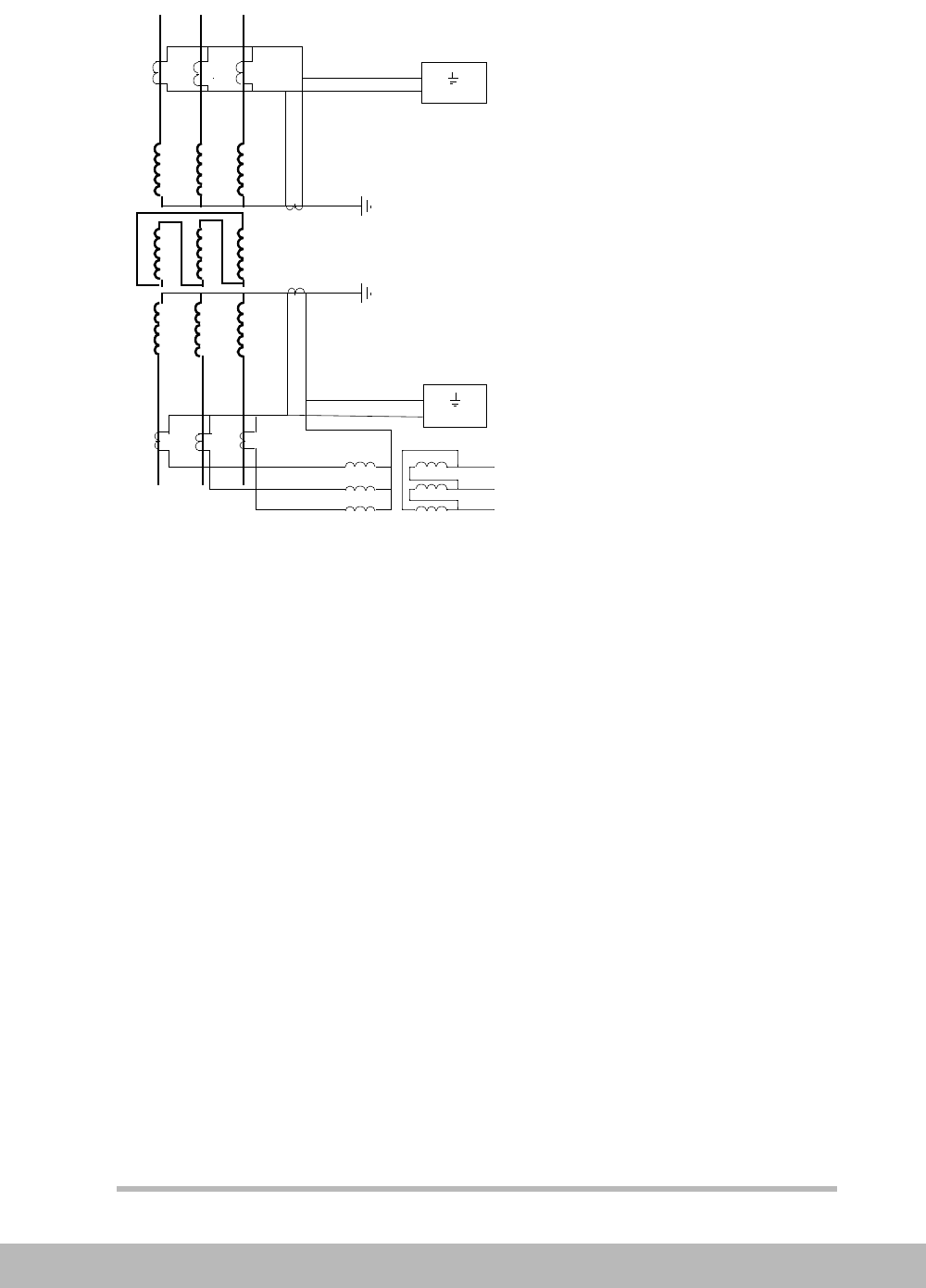
The connection of a restricted earth fault relay is shown in Figure
3. It is connected across each transformer winding in the figure.
Figure 3. A restricted earth fault relay for an YNdyn transformer.
It is quite common to connect the Restricted earth fault relay in
the same current circuit as the transformer differential relay. This
will due to the differences in measuring principle limit the differ-
ential relays possibility to detect earth faults. Such faults are de-
tected by the REF. The mixed connection is shown in the low
voltage winding of the transformer, see figure 3.
To Diff
protection
Id
Id

EFFECTIVELY EARTHED SYSTEMS
208
BA THS / BU Transmission Systems and Substations
LEC Support Programme
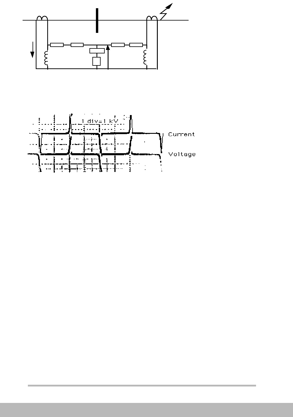
The common principle for Restricted earth fault relays is the high
impedance principle, see figure 4.
Figure 4. The high impedance principle.
The relay provides a high impedance to the current. The current
will, for through loads and through faults, circulate in the current
transformer circuits, not go through the relay.
For a through fault one current transformer might saturate when
the other still will feed current. For such a case a voltage can be
achieved across the relay. The calculations are made with the
worst situations in mind and an operating voltage “U
R
” is calcu-
lated:
where
“I
Fmax
” is the maximum through fault current at the secondary
side,
“R
ct
” is the current transformer secondary resistance and
“R
l
” is the loop resistance of the circuit.
U
R
e1 e2
Is
Rct RL RL Rct
I
F
Xm2
Xm1
Secondary current and voltage with
no voltage limiter.
Z=>0
at sat.
U
R
I
Fmax
R
ct
R
I
+()≥

EFFECTIVELY EARTHED SYSTEMS
Earth Fault Protection
for worldwide cooperation
209
BA THS / BU Transmission Systems and Substations
LEC Support Programme
The maximum operating voltage have to be calculated (both neu-
tral loop and phase loop must be checked) and the relay set high-
er than the highest achieved value.
For an internal fault the circulation is not possible and due to the
high impedance the current transformers will immediately satu-
rate and a rms voltage with the size of current transformer satu-
ration voltage will be achieved across the relay. Due to the fast
saturation very high top voltages can be achieved. To prevent the
risk of flashover in the circuit, a voltage limiter must be included.
The voltage limiter can be either of type surge arrester or voltage
dependent resistor.
The relay sensitivity is decided by the total current in the circuit
according to the formula:
where
“n” is the CT ratio, “I
R
” is the current through the relay, “I
res
”
is the current through the voltage limiter and “∑I
mag
” is the sum of
the magnetizing currents from all CT’s in the circuit (normally 4).
It should be remembered that the vectorial sum of the currents
must be used. The current measurement have to be DC insensi-
tive to allow a use of AC components of the fault current in the
calculations.
2.4 LOGARITMIC INVERSE RELAY
Detection of earth fault and back-up tripping with maintained se-
lectivity in a solidly (effectively) earthed system is rather compli-
cated due to the infeed of fault current from different direction
concerning all faults. A special inverse characteristic with a log-
aritmic curve has been developed to be suitable for these appli-
cations. The principle for earth fault relays in a effectively earthed
system is shown in figure 5 and the logaritmic inverse character-
istic is shown in figure 6. The inverse characteristic is selected so
I
p
nI
R
I
res
ΣI
mag
++()≥

EFFECTIVELY EARTHED SYSTEMS
210
BA THS / BU Transmission Systems and Substations
LEC Support Programme
that if the current of the largest infeed is less than 80% of the
faulty objects current selectivity is achieved.
Figure 5. Earth fault protection in a solidly earthed system.
Figure 6. The logaritmic inverse characteristic. A fault current of the biggest
infeed less than 0,8 times the current of the faulty object, gives a selective
tripping.
I I
I
I
I
I
