Paulo D.J. Surface Integrity in Machining
Подождите немного. Документ загружается.

6 Surface Integrity of Micro- and Nanomachined Surfaces 183
tool was operated in a steady-state two-dimensional orthogonal cutting mode as it
machined the end of the tube. Values of shear stress on the shear plane (
τ
) versus
undeformed chip thickness were determined for experiments at a constant cutting
speed and different values of axial infeed rate and for variable cutting speeds and
a constant axial infeed rate [1]. A true stress–strain tensile test was performed on
a 0.505-inch (1.28
cm) diameter by 2-inch (5.08
cm) gage length specimen of SAE
1112 steel. The mean shear stress at fracture was 22,000
psi (151.7
MPa). This
value is not shown in Figure 6.1 since it falls too far to the right. Taniguchi dis-
cussed the size effect in cutting and forming [2]. Shaw [3] discusses the origin of
the size effect in metal cutting, which is believed to be primarily due to short-range
inhomogeneities present in all engineering metals. When the back of a metal cutting
chip is examined at very high magnification by means of an electron microscope
individual slip lines are evident. In deformation studies, Heidenreich and Shockley
[4] found that slip does not occur on all atomic planes but only on certain discrete
planes. In experiments on deformed aluminum single crystals the minimum spacing
of adjacent slip planes was found to be approximately 50 atomic spaces, while the
mean slip distance along the active slip planes was found to be about 500 atomic
spaces. These experiments further support the observation that metals are not ho-
mogeneous and suggest that the planes along which slip occurs are associated with
inhomogeneities in the metal. Strain is not uniformly distributed in many cases. For
example, the size effect in a tensile test is usually observed only for specimens less
than 0.1
inch (2.5
mm) in diameter. On the other hand, a size effect in a torsion test
occurs for considerably larger samples due to the greater stress gradient present in
a torsion test than in a tensile test. This effect and several other related ones are
discussed in detail by Shaw [3].
6.2.1 Shear-angle Prediction
There have been many notable attempts to derive an equation for the shear angle
(
φ
) shown in Figure 6.1 for steady-state orthogonal cutting. Ernst and Merchant [5]
presented the first quantitative analysis. Figure 6.2 shows forces acting on a chip at
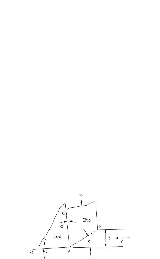
Figure 6.1. Nomenclature for two-dimensional steady-state orthogonal cutting process
184 M.J. Jackson
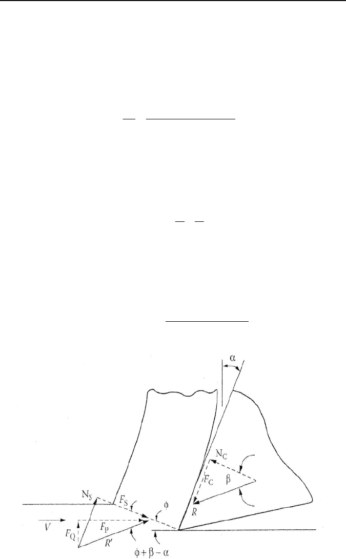
the tool point where: R = the resultant force on the tool face, R’ = the resultant
force in the shear plane, N
C
and F
C
are the components of R normal to and parallel
to the tool face, N
S
and F
S
are the components of R' normal to and parallel to the
cutting direction, F
Q
and F
P
are the components of R normal to and parallel to the
cutting direction, and
β
= tan
–1
F
C
/N
C
(is called the friction angle).
Assuming the shear stress on the shear plane (
τ
) to be uniformly distributed it is
evident that:
()
A
R
A
F
φαβφ
τ
sincos'
S
S
−+
==
, (6.1)
where A
S
and A are the areas of the shear plane and that corresponding to the width
of cut (b), times the depth of cut (t). Ernst and Merchant [5] reasoned that
τ
should
be an angle such that τ would be a maximum and a relationship for
φ
was obtained
by differentiating Equation 6.1 with respect to
φ
and equating the resulting expres-
sion to zero produces,
22
45
αβ
φ
+−=
. (6.2)
However, it is to be noted that in differentiating, both R' and
β
were considered
independent of
φ
.
Merchant [6] presented a different derivation that also led to Equation 6.2. This
time an expression for the total power consumed in the cutting process was first
written as,
()
()
()
αβφφ
αβ
τ
−+
−
==
cossin
cos
P
AVVFP
. (6.3)
Figure 6.2. Cutting forces at the tool tip for the cutting operation shown in Figure 6.1

6 Surface Integrity of Micro- and Nanomachined Surfaces 185
It was then reasoned that
φ
would be such that the total power would be a mini-
mum. An expression identical to Equation 6.2 was obtained when P was differenti-
ated with respect to
φ
, this time considering
τ
and
β
to be independent of
φ
. Piis-
panen [7] had done this previously in a graphical way. However, he immediately
carried his line of reasoning one step further and assumed that the shear stress
τ
would be influenced directly by normal stress on the shear plane as follows,
σ
τ
τ
K+=
0
, (6.4)
where K is a material constant. Piispanen then incorporated this into his graphical
solution for the shear angle. Upon finding Equation 6.2 to be in poor agreement
with experimental data Merchant also independently assumed that the relationship
given in Equation 6.4, and proceeded to work this into his second analysis as fol-
lows. From Figure 6.2 it may be seen that,
()
α
β
φ
τ
σ
−+= tan
, (6.5)
or, from Equation 6.4
()
α
β
φ
τ
τ
τ
−++= tan
0
K
. (6.6)
Hence,
()
0
1tanK
τ
τ
ϕ
βα
=
−+−
. (6.7)
When this is substituted into Equation 6.3 we have,
()
()
[]
()
αβφφαβφ
α
β
τ
−+−+−
−
=
cossintan1
cos
0
K
AV
P
. (6.8)
Now, when P is differentiated with respect to
φ
and equated to zero (with
τ
0
and
p considered independent of
φ
we obtain,
()
2222
cot
1
αβαβ
φ
+−
=+−=
−
CK
. (6.9)
Merchant called the quantity, cot
–1
K
,
the machining “constant” C. The quantity
C is seen to be the angle the assumed line relating
τ
and
φ
makes with the
τ
-axis
[6, 7, 9]. Merchant [8] has determined the values of C given in Table 6.1 for mate-
rials of different chemistry and structure being turned under finishing conditions
with different tool materials. From this table it is evident that C is not a constant.
Merchant’s empirical machining “constant” C that gives rise to Equation 6.9 with
values of
φ
is in reasonably good agreement with experimentally measured values.
While it is well established that the rupture stress of both brittle and ductile mate-
rials is increased significantly by the presence of compressive stress (known as the
Mohr effect), it is generally believed that a similar relationship for flow stress does
not hold. However, an explanation for this paradox with considerable supporting
experimental data is presented below. The fact that this discussion is limited to
steady-state chip formation rules out the possibility of periodic gross cracks being

186 M.J. Jackson
involved. However, the role of microcracks is a possibility consistent with steady-
state chip formation and the influence of compressive stress on the flow stress in
shear. A discussion of the role microcracks can play in steady-state chip formation is
presented in the next section. Hydrostatic stress plays no role in the plastic flow of
metals if they have no porosity. Yielding then occurs when the von Mises criterion
reaches a critical value. In general, if a small amount of compressibility is involved
yielding will occur when the von Mises criterion reaches a certain value. However,
based on the results of Table 6.1 the role of compressive stress on shear stress on the
shear plane in steady-state metal cutting is substantial. The fact there is no outward
sign of voids or porosity in steady-state chip formation of a ductile metal during
cutting and yet there is a substantial influence of normal stress on shear stress on the
shear plane represents an interesting paradox. It is interesting to note that Piispanen
[7] had assumed that shear stress on the shear plane would increase with normal
stress and had incorporated this into his graphical treatment. References [9–39]
describe, in detail, the nature of chip formation as a function of crack generation
during machining. It should be noted that cracks are propagated into the bulk of the
material as chips form on the surface. Hence, cracks are ever present in the surface of
the material that contributes to a reduction in the fatigue strength of the material.
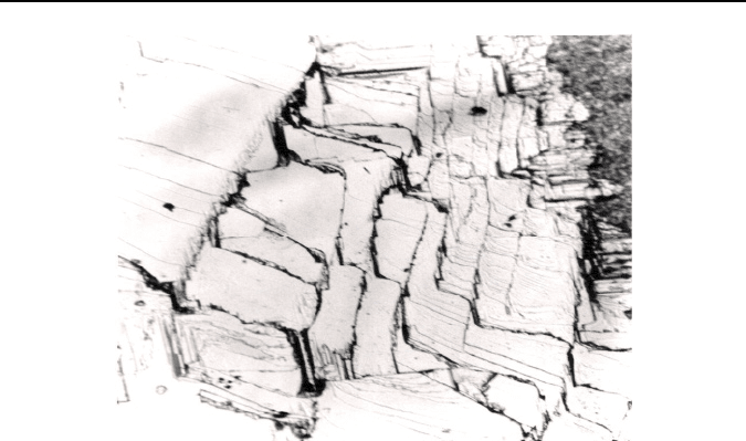
Figure 6.3 shows the cracks present on a freshly cleaved surface of single-crystal
lithium fluoride. Therefore, the measurement of surface integrity becomes critical at
the microscale in order to monitor the depth to which those cracks have penetrated
into the bulk of the material and rendered its properties damaged beyond function.
Table 6.1. Values of C in Equation 6.9 for a variety of work and tool materials in finish
turning without a cutting fluid
Work material Tool material C (degrees)
SAE 1035 Steel HSS* 70
SAE 1035 Steel Carbide 73
SAE 1035 Steel Diamond 86
AISI 1022 (leaded) HSS* 77
AISI 1022 (leaded) Carbide 75
AISI 1113 (sulfurized) HSS* 76
AISI 1113 (sulfurized) Carbide 75
AISI 1019 (plain) HSS* 75
AISI 1019 (plain) Carbide 79
Aluminum HSS* 83
Aluminum Carbide 84
Aluminum Diamond 90
Copper HSS* 49
Copper Carbide 47
Copper Diamond 64
Brass Diamond 74
* HSS = High-speed steel
6 Surface Integrity of Micro- and Nanomachined Surfaces 187
Figure 6.3. Unpolished surface of the LiF single crystal showing cleavage steps
6.2.2 Pulsed Waterdrop Micromachining
Micromachining of semiconductor materials is of critical importance to electronic
industries that rely on the removal of material from single crystals. Traditional
methods use grinding and polishing techniques to remove material with variable
material removal rates. However, these techniques impart high machining stresses
in the substrate that tend to produce microcracks that are not desirable, especially
when one considers that subsequent deposition of metals and non-metals can be
comprised owing to the creation of cracks in and on the surface. However, pulsed
erosion of single crystals can be performed that minimize the size of those cracks
by carefully selecting the removal of substrate material directly from the surface
as opposed to the bulk of the substrate using a specially designed pulsed water
drop impact machine tool. Pulsed water drop machining uses a tetrahedral ma-
chine tool that specifically absorbs dynamic and regenerative vibrations that pre-
vent microcracks from expanding during the micromachining operation. The proc-
ess minimizes the level of stresses induced in the surface of the semiconductor
material.
Single-crystal materials were initially impacted with methanol, water, oil, and
mercury drops then etched to reveal dislocation activity on the surface of the crys-
tals. However, Jolliffe did not impact single-crystal MgO beyond its damage thresh-
old. Jolliffe noted that dislocation movement due to repeated impact by liquids is
caused by the extension of dislocation loops to form slip bands on {110}
45
° planes.
The nature of impact damage in single-crystal magnesium oxide due to liquid impact
was in the form of slip bands in <100> directions until the material reached its dam-
age threshold. When the limit was reached, {110}-type cracks appeared in <100>
directions that were formed by the interaction of {110}
45
° slip planes. In addition to
the characteristic slip-band pattern for single- and multiple impacts on (001) magne-

188 M.J. Jackson
sium oxide, there is a fracture annulus surrounding the impact zone. The cracks
within the fracture annulus have the following characteristics:
(I) Microcracks at the release radius are very short in length.
(II) Microcracks exist in an annulus whose boundary is square in shape with a
slight tendency to be elliptical. The diagonals associated with this annulus are
the [010] and [100] directions.
(III) Owing to symmetry in four directions around the [001] impact axis, the dam-
age is the same in eight octants.
(IV) Microcracks intersect the surface tangent to the impact release radius within
the <100> radial directions.
(V) Microcracks located near to <110> radial directions are of two varieties.
Those that intersect on the (001) impact face, and those that are apparent dis-
tortions in the radial direction of type (II) fractures. Intersections of these
cracks from two quadrants form W-shaped cracks.
The characteristic microcracks have been identified in single-impact water-drop
experiments. Cracks found immediately at the release radius are short in depth (less
than 5
μm) and are thought to be cracks created by grinding and polishing that are
excited by the passing Rayleigh wave. The onset of visible cracking at the release
radius was used as a measure of the damage threshold of the material at a known
impact velocity. This tends to give a conservative estimate of the absolute damage
threshold of the material. At the point where damage occurs is the point at which
material is removed. This process has been adapted to remove material at the micro-
scale and uses the precise location of impacting liquid droplets with minimal fracture
tendency.
An experimental investigation concerning the machining of single-crystal materi-
als using pulsed droplet impact was conducted using a specially designed pulsed drop
machining center using a tetrahedral framework structure. This apparatus has been
discussed elsewhere and functions in much the same way as a multiple-impact jet
apparatus, the only difference being in the way that the vibrations are absorbed by the
structure once impacts take place. Lithium fluoride is used as the model material. The
experimental procedure involves using this apparatus to remove small amounts of
material using drops of liquid approximately 1–1.5
mm in diameter. The machining
center uses a two-stage pressure reservoir to accelerate a nylon piston into a titanium
shaft positioned at the rear of a liquid-filled nozzle. Owing to the high solubility of
water in lithium fluoride, hexadecane (C
16
H
34
) was used as the impacting fluid. The
rapid insertion of the shaft into the nozzle forces a high-velocity jet of liquid from the
orifice onto the sample that is located on a computer-controlled x-y stage. The com-
puter monitors the velocity of the jet of liquid as it emerges from the orifice.
Single crystals of lithium fluoride in the form of undoped high-purity single
crystals were initially unpolished. Figure 6.3 shows the unpolished stepped surface
showing terraces of cleavage steps. Crystran prepared the specimens for impact
experiments by cleaving and polishing the crystals. The crystals were cleaved to
size on {100} planes and mechanically polished on one side to remove cleavage
steps. Chemical polishing was performed to remove mechanically induced polish-
ing dislocations from the surface of the crystal. This was achieved by immersing
the crystals in a bath of hydrochloric acid (HCl) at 50°C followed by immersion in
6 Surface Integrity of Micro- and Nanomachined Surfaces 189
ammonium chloride (NH
4
Cl) to remove etch pits. A light mechanical polish using
0.25
μm diamond paste followed immersion in order to obtain a clean surface. The
surfaces were then orientated to within two degrees of a {100} plane. The impact
face was denoted the (001) plane. The properties of single-crystal lithium fluoride
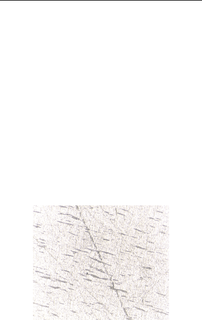
are shown in Table 6.2. Figure 6.4 shows the surface of the initially etched surface
of the lithium fluoride single crystal. The erosion resistance of a material is charac-
terized by determining its absolute damage threshold velocity (ADTV), or the point
at which material is removed from the surface. This is the velocity below which,
for a given liquid drop size, the sample will never experience any damage regard-
less of the number of impacts to which it is exposed, but will experience disloca-
tion motion. Owing to the high accuracy of the impact velocity and positioning,
this parameter can be simply obtained from a single-crystal sample. The sample
(typically a twenty-five millimeters’ diameter disc) has up to fifteen sites selected
on its surface, each one allocated an impact velocity. Each site was initially im-
pacted once at that velocity and inspected for damage using an optical microscope
at one hundred times magnification. The lowest velocity at which damage is ob-
served after a single impact was recorded as damage threshold velocity (D.T.V.) at
one impact, i.e. the single-impact threshold velocity, and the sample returned to the
multiple impact jet apparatus so that each site can be impacted again.
Impact damage was detected by inspecting the surface of impact using an optical
microscope. After the crystal was impacted it was etched to reveal dislocation
movement and the formation of surface cracks. The samples were thoroughly washed
in a solution of water and non-ionic surfactant prior to etching the (001) surface.
Once the sample was dried, hydrogen peroxide (H
2
O
2
) was used to reveal etch pits
and regions of crack formation. Each sample was etched for ten minutes at room
temperature. The purpose of this exercise was to determine the impact conditions
where material removed is activated by the formation of microcracks on the surface
Figure 6.4. Initially etched surface of the (001) plane of single-crystal lithium fluoride show-
ing polishing dislocations

190 M.J. Jackson
of the material. The damage pattern observed after liquid impact on single-crystal
lithium fluoride was typically a series of discrete circumferential cracks around an
undamaged central zone. The cracks observed immediately outside the release radius
are type-III cracks that were used to detect the onset of the damage threshold. The
pressure pulses produced by liquid impact are intense because of the compressible
behavior of the liquid in the first stages of impact. Damage observed in single-crystal
lithium fluoride was in the form of slip-band development in <100> directions until
the material reached its damage threshold limit, or machining limit. At the damage
threshold limit a number of fractures and types of fracture are evident. In addition to
type-III cracks at the release radius, type-IV cracks are observed in <100> directions.
Figure 6.5 shows type-IV cracks to the right of the photograph. The cracks shown are
variable in length; the largest emanating from the center of impact that, unusually,
has a subsidiary crack running in the <110> direction. Referring to type-III cracks,
substantial surface and near-surface tensile stresses developed ahead of the shear
wave in polycrystalline zinc sulfide just before the Rayleigh surface wave begins to
develop. However, there was no evidence in the case of single-crystal lithium fluo-
ride of subsurface tensile cracking associated with bulk waves. Type-III cracks at the
periphery of the impact zone did not have subsidiary cracks attached to them at trajec-
tories associated with bulk waves. Although when one looks at a cross-section of
type-IV cracks some distance away from the center of impact, there was evidence of
subsurface tensile cracks that were presumably caused by the interaction of {110}
45
°
slip planes.
Figure 6.5 also shows the existence of type-V cracks. These cracks are apparent
distortions of type-II cracks in the radial <110> directions. Figure 6.6 shows the
intersections of these cracks from two quadrants. They are typically W-shaped
cracks and are associated with liquid impact on single-crystal materials, particu-
larly magnesium oxide. The increase in the number of W-shaped cracks occurred
beyond the damage threshold limit of the material and was largely associated with
the appearance of cracks in the <100> radial directions within the impact zone.
Table 6.2. Properties of single-crystal lithium fluoride
Young’s modulus, E
<100>
, (MPa) 64.8
Poisson’s ratio,
ν
<100>
0.27
Density,
ρ
, (kg m
–3
)
2600
Fracture toughness, K
IC <100>
, (MPa m
1/2
) 0.2
Slip system
{}
>< 011110
Cleavage plane {100}
Water solubility, (mg/100 g water) 270
Knoop hardness (kg mm–2)
(001)<100>
(001)<110>
(110)<001>
>< 111)011(
(110)<110>
87–96
93–103
87–98
97–120
93–116
6 Surface Integrity of Micro- and Nanomachined Surfaces 191
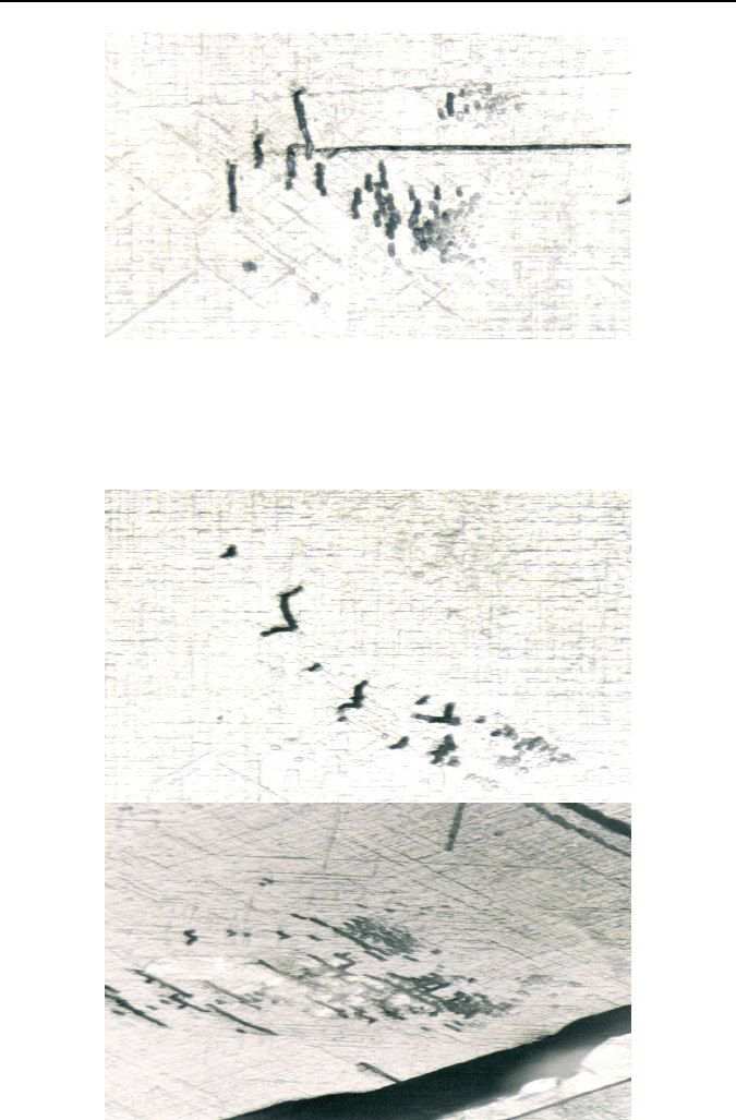
Figure 6.5. Dislocation-etched (001) impact face of single-crystal lithium fluoride. Hexa-
decane was used to impact the surface at 200 m s
–1
through a 0.8
mm diameter nozzle. The
Figure shows type-IV cracks in <100> radial directions, type-V cracks to the left of type-IV
cracks, and a central impact crack some distance away from the center of impact
Figure 6.6. Dislocation-etched (001) impact face of single-crystal lithium fluoride. Hexa-
decane was used to impact the surface at 200 m s
–1
through a 0.8
mm diameter nozzle. The
Figure shows cracks that are apparent distortions in the radial direction of type-II cracks.
Intersections of these cracks from two quadrants form W-shaped cracks as shown
192 M.J. Jackson
In some materials, repeated impact produces local failure on, or near the impact
axis. In this case, the damage was located beneath the surface at a depth of about
half the radius of the contact region R. This is where Hertz theory for elastic contact
would predict the maximum shear stress. However, for loading that is dominated by
a stress wave this is unlikely to be the full explanation. Experiments show that sub-
surface axial cracks in PMMA form when the release waves from the contact pe-
riphery interact giving net tension. Interestingly, the release waves will also travel
in the liquid giving cavitation when they cross. A third mechanism for damage at or
near the central axis with polycrystalline materials is by the action of compressive
or shear loading that generates tensile failure at grain boundaries between grains
depending on their orientation and anisotropy. Once a pit develops, hydraulic load-
ing by trapped liquid can develop damage. Central damage is likely to be less im-
portant than circumferential cracking in the rain erosion situation since it depends
on multiple impacts on the same site.
Central impact damage in single-crystal lithium fluoride initially occurs as slip
bands move causing a “rippling” effect to be seen in the centrally loaded impact zone.
As slip-band development continues after repeated impact, cracks begin to appear
above the damage threshold limit, i.e., after type-III and -IV cracks have been estab-
lished. Slip development leads to cracks predominantly in the [010] direction. As the
severity of the impacts increases, cracking occurs in all principal <100> directions.
These cracks are thought to be due to the interaction of {110}
45
° slip planes. The most
likely explanation for central impact damage in single-crystal lithium fluoride is that
hydrostatic compressive loading during impact enables subsurface slip bands to in-
teract, i.e., shear interactions of slip planes. The slip planes, which have a greater
tendency to slip, will do so, thus causing a “rippling” effect on the surface of the im-
pact site. As the severity of impact continues, {110}-type cracks form due to the in-
teraction of {110}
45
° slip planes. It should be noted that they did not observe cracks
within the central impact region of single-crystal magnesium oxide. However, they
did notice that slip-plane interactions did occur within the central impact region but
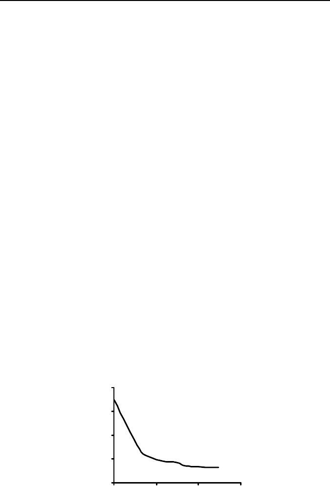
without crack formation. The damage threshold curve for single-crystal lithium fluo-
ride subjected to multiple liquid impact is shown in Figure 6.7. The single-impact
0
50
100
150
200
1 10 100 1000
Number of impacts
Liquid impact velocity (m/s)
Figure 6.7. Experimental damage threshold curve for single-crystal lithium fluoride. The
single-shot threshold velocity from a 0.8
mm diameter nozzle is 175 m s
–1
, whilst the ma-
chining threshold velocity after three hundred impacts was 32 m s
–1
.