Paulo D.J. Surface Integrity in Machining
Подождите немного. Документ загружается.

152 W. Grzesik, B. Kruszynski, A. Ruszaj
5.2.2 Drilling and Reaming Operations
Hole making is among the most important operations in manufacturing and one of
the most common is drilling. Drilling is associated with subsequent machining
operations such as trepanning, counterboring, reaming and boring. Common to all
these processes is a main rotating movement combined with a linear feed. Drilling
can be performed with classical twist drills, brazed and solid cemented carbide
twist drills, drills with through-collant holes and indexable insert drills of various
insert clamping systems.
With modern tools, the hole quality is good and subsequent operations for
improving accuracy and surface texture are often unncessary. The achievable hole
tolerances are almost halved to +0.25
mm (IT 7) and with moderate feed possible
surface finish is 0.5
μm R
a
. Typically, hole tolerances for brazed and solid
cemented carbide twist drills can be within IT8 and finishes within 1
μm R
a
de-
pending on drill length, tool holding and machining parameters.
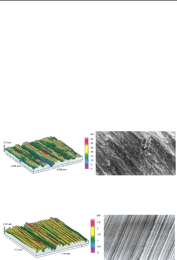
Figure 5.9 presents an exemplary surface topography of a cylindrical hole sur-
face and a set of appropriate 3D roughness parameters. For this case the surface
structure is mixed anisotropic with determination coefficient of S
Kd
=0.16.
(a)
(b)
Figure 5.9. Scanned topography (a) and optical image at magnification 200× (b) of surfaces
after drilling of C45 carbon steel with high-speed steel twist drill at v
c
=
0.6
m/s and
f
=
0.15
mm/rev. Roughness parameters: (a) S
a
=
3.59
μm, S
t
=
37.3
μm, S
sk
=
−0.1, S
ku
=
3.2
(a)
(b)
Figure 5.10. Scanned topography (a) and optical image at a magnification of 200× (b) of
surfaces after finish reaming of C45 carbon steel with a Ti(C,N) coated high-speed steel
reamer at v
c
=
0.8
m/s and f
=
1.4
mm/rev. Roughness parameters: S
a
=
0.356
μm, S
t
=
2.81
μm,
S
sk
=
−0.191, S
ku
=
2.57
5 Surface Integrity of Machined Surfaces 153
Accuracy of the hole (achievable tolerances after reaming are within IT6-10)
and quality of finish produced by reaming depend primarily upon the condition of
the starting hole, rigidity of the machine and fixture, correct speed and feed, and a
suitable and properly applied cutting fluid. To obtain smooth hole finishes (R
a
parameter below 0.63
μm) reamers must operate without chatter or process insta-
bilities. In comparison to the effect of drilling from Figure 5.9, Figure 5.10(a) pre-
sents the surface topography of the hole surface made by reaming and appropriate
3D roughness parameters. For this case the surface structure is random anisotropic
with isotropic component of 6.12%.
5.2.3 Milling Operations
The surface finish in milling is, in comparison to turning and boring, affected by
a number of additional factors resulting from differences in tooling construction and
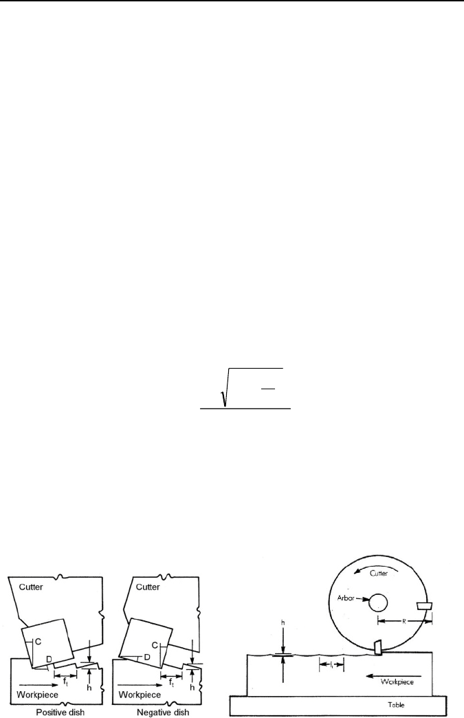
process kinematics. The formation of rouhgness in face and peripheral (slab) milling
operations using multitoothed cutters is shown schematically in Figure 5.11.
The surface roughness or waviness in face milling operations is determined by
insert nose geometry, feed per tooth (insert), spindle and cutter runout, and stability
of the workpiece and fixturing interact. When a radiused insert is used, the
theoretical average roughness R
a
(CLA) can be calculated as
2
2
2
t
2
at
⎟
⎠
⎞
⎜
⎝
⎛
−−
=
f
rr
R
, (5.2)
where: r is nose radius and f
t
is feed per tooth (insert).
It should be noted that Equation 5.2 is exact for a single-toothed cutter called fly
mill without spindle runout. In finish milling, fine finishes are often produced using
cutters with corner chamfered inserts or wiper inserts. When using corner chamfer
inserts, the chamfer should be parallel to the machined surface and the feed per
(a)
(b)
Figure 5.11. Schemes to calculate theoretical roughness in face (a) and peripheral (b) milling
operations
154 W. Grzesik, B. Kruszynski, A. Ruszaj
tooth should be less than the chamfer length. In practice, the insert land may not
always be parallel to the direction of the feed and both negative and positive dishes
are used, as depicted in Figure 5.11. In such a case, an estimate of peak-to-valley
(P−V) roughness height is based on the following formula:
,
cottan
t
zt
DC
f
R
+
=
(5.3)
where: f
t
is feed per tooth (insert), D is the face clearance angle (dish), C is the lead
angle if dish is positive or trailing angle if dish is negative.
In most face milling applications, the spindle is tilted slightly in the direction of
feed to provide relief or dish behind the cut. Spindle tilt produces a concave
machined surface and results in a flatness error. The depth of the concavity d
f
can
be calculated from the Kirchner−Schulz formula [3]:
⎥
⎥
⎥
⎦
⎤
⎢
⎢
⎢
⎣
⎡
⎟
⎟
⎠
⎞
⎜
⎜
⎝
⎛
−−Θ=
2
1
22
ee
f
442
tan
eDD
d
, (5.4)
where: D
e
is the effective diameter of the cutter, e is the width of the workpiece and
Θ
is the spindle tilt angle.
The P−V roughness height generated by up and down peripheral milling can be
obtained by means of the following formula:
⎟
⎠
⎞
⎜
⎝
⎛
×
±×
=
π
Nf
R
f
R
t
2
t
zt
8
, (5.5)
where: R is cutter radius, N is number of teeth in cutter and f
t
is feed per tooth
(insert). Sign (+) is valid for up milling and (−) for down milling.
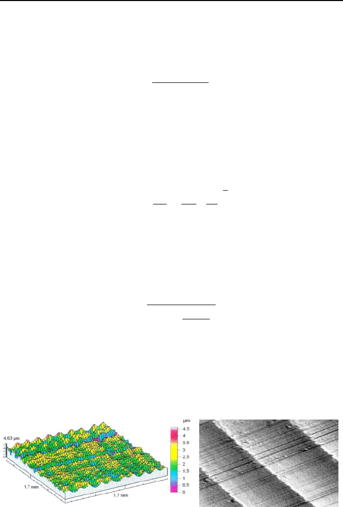
Figures 5.12 and 5.13 present exemplary surface topographies of milled surfaces
after finish peripheral and face milling operations respectively, along with sets of
appropriate 3D roughness parameters.
(a)
(b)
Figure 5.12. Scanned topography (a) and optical image at a magnification of 160× (b) of
surfaces after finish peripheral milling of aluminum-silicon alloy (0.5% Si) with a CrN
coated carbide cutter at v
c
=
4.1
m/s and f
=
7.2
m/min. Roughness parameters: S
a
=
0.51
μm,
S
t
=
4.63
μm, S
sk
=
−0.12, S
ku
=
3.23, surface structure-periodic anisotropic
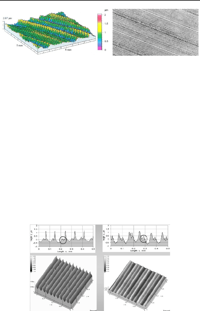
5 Surface Integrity of Machined Surfaces 155
(a)
(b)
Figure 5.13. Scanned topography (a) and optical image at a magnification of 250× (b) of sur-
faces after finish face milling of low alloy steel with a TiN coated P10 carbide end-mill of
14
mm in diameter at v
c
=
4.6
m/s and f
=
0.96
mm/rev. Roughness parameters: S
a
=
0.232
μm,
S
t
=
2.07
μm, S
sk
=
0.19, S
ku
=
2.75, surface structure-mixed anisotropic
5.2.4 Hard Machining Operations
Figure 5.14 presents some characteristic surface profiles and corresponding 3D
topographies for hard turning (HT) with CBN (Figure 5.14(a)) and mixed ceramic
(Figure 5.14(b)) tools at the same cutting parameters (v
c
=100 m/min, f=0.1
mm/rev
and a
p
=0.2
mm). It can be noted that the relevant surface profiles contain more
sharp (CBN HT) or blunt (MC HT) peaks with characteristic lateral smaller flashes
(circled in upper surface profiles) resulting from a side-flow effect.
3D surface roughness parameters for the surface turned with CBN tools with a
tool nose of 0.8
mm and feed of 0.1
mm/rev are: S
a
=0.34
μm, S
z
=2.93
μm, S
ku
=3.28
and S
sk
=1.68. On the other hand, the corresponding roughness parameters obtained
after turning of a 60 HRC alloy steel with mixed ceramic tools are: S
a
=0.53
μm,
S
t
=3.47
μm, S
ku
=2.27 and S
sk
=1.43.
Characteristic surface profiles generated by conventional and wiper ceramic
tools are magnified in Figure 5.15. It was observed that due to the smoothing effect
(a) (b)
Figure 5.14. Typical surface profiles and corresponding 3D visualizations produced in CBN
HT (a) and MC HT (b) hard turning operations [4]
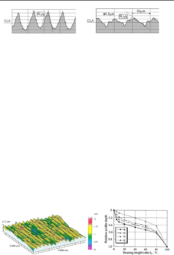
156 W. Grzesik, B. Kruszynski, A. Ruszaj
wiper tools produce blunt irregularities with the RMS profile slope ranging from
RΔq
=
1.5° to 5.5° as in Figure 5.15b. On the other hand, more sharp profiles with
RΔq values of 5−10° were recorded for standard tools (Figure 5.15(a)). As can be
expected, distinct differences in surface profile shapes will result in corresponding
bearing area values and further in the contact capabilities of surfaces.
5.2.5 Broaching and Burnishing Operations
Broaching is usually employed to machine fast in a single stroke some form of ex-
ternal or internal surfaces on a part. Typical internal broaching operations are the
sizing of circular and noncircular holes and cutting of serrations, slots, straight or
helical internal splines, gun rifling, and keyway cutting. Good finish and accuracy
are obtainable over the life of a broach because roughing and finishing are done by
separate teeth. Hence, it competes favorably with other processes, such as boring,
milling, shaping, and reaming to produce similar shapes. As can be seen in Fig-
ure 5.4 broached surfaces with 0.4
μm R
a
roughness and IT6(5) dimension tolerance
are achievable. Typical broaching operations are used to produce a surface finish of
3.2−0.8
μm R
a
, which corresponds to IT 9(8) ISO tolerance. Surface profile contains
randomly distributed irregularities and texture lays are parallel to the linear travel of
a broach.
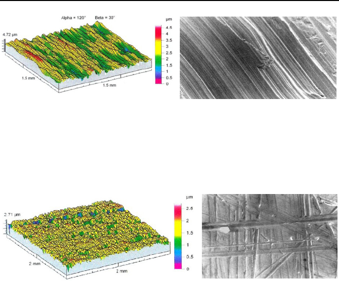
Roller burnishing is a surface finishing operations in which hard, smooth rollers
or balls are pressed against the work surface to generate the finished surface
(a)
(b)
Figure 5.15. Characteristic shapes of the profiles generated in turning with conventional (a)
and wiper (b) ceramic tools for constant cutting speed of 100
m/min and feed rate of
0.1
mm/rev. Vertical magnification −7000×. Horizontal magnification −200× [5]
(a)
(b)
Figure 5.16. Scanned topography after diamond burnishing of 45C steel with v
b
=
0.8
m/s
and f
=
0.07
mm/rev (a) and the bearing curves of surfaces with R
a
=
0.1
μm processed by:
(B) grinding, (C) polishing, (D) superfinishing and (E) burnishing (b). Roughness para-
meters: S
a
=
0.245
μm, S
t
=
2.12
μm, S
sk
=
0.14, S
ku
=
2.63, surface structure: mixed-periodic
anisotropic

5 Surface Integrity of Machined Surfaces 157
through plastic deformation. Burnishing is used to improve surface finish, control
tolerance, increase surface hardness, and induce compressive residual stresses in
order to improve fatigue life. Turned, bored and milled surfaces with roughnesses
between 2 and 5
μm are suitable for burnishing because they have uniform as-
perities. When the initial surface roughness is R
a
=
1.5−2.0
μm, it is reduced down to
0.05−0.3(0.5)
μm (Figure 5.16(b)) by single or multipass operations and the bearing
length ratio t
p
30 can approach 30−50%, as shown in Figure 5.16(b). Part dimen-
sional accuracies can often be controlled within ±5
μm with proper part preparation.
5.2.6 Grinding Operations
Grinding is often used to produce parts with fine surface finishes and tight toler-
ances. As can be seen in Figure 5.4 ground surfaces with 0.1
μm R
a
roughness and
IT6(5) dimension tolerance are achievable. Typical grinding operations are used to
produce surface finish of 1.6−0.1
μm R
a
that corresponds to IT (8-5) ISO tolerance.
The surface profile contains randomly distributed irregularities and texture lays
depend on the grinding method used (they are parallel in cylindrical grinding, ra-
dial in face grinding, concentric in cup grinding). Figures 5.17 and 5.18 present
exemplary surface topographies and optical images of ground surfaces under de-
fined operation conditions, along with sets of appropriate 3D roughness parameters
and characteristic surface features.
When the wheel is dressed frequently so the wheel wear is not a significant
variable, the ground surface finish depends primarily on the grinding conditions,
wheel type and wheel dressing method. In particular, smoother surface finishes are
usually obtained with fine-grained wheels; as the wheel grit size increases, the
effective spacing of cutting edges decreases, so the roughness peaks are more
closely spaced and thus shorter. Also, a smoother finish is usually obtained if the
wheel hardness increases. Finally, it should be noted that the ground surface finish
deteriorates markedly if chatter occurs.
A number of equations for the geometric roughness in grinding have been
proposed [6]. For example, the theoretical R
a
value in cylindrical plunge grinding
can be estimated by the equation
x
v
av
RR
⎥
⎦
⎤
⎢
⎣
⎡
=
s
w
1at
, (5.6)
where: v
w
is the workpiece velocity, v
s
is the wheel velocity, a is the depth of cut
during the spark-out phase, and R
1
is empirical coefficient and exponent x=0.15−0.6.
On the other hand, this roughness parameter in cylindrical grinding can be
calculated as follows:
0.13
bm
6
1
eq
3
1
'
n
3.0
fd
d
5.0
fd
3at
HRC
2
VD
F
v
av
KR
⎟
⎟
⎠
⎞
⎜
⎜
⎝
⎛
⎟
⎠
⎞
⎜
⎝
⎛
=
ρ
, (5.7)
where: K
3
is a constant that considers wheel characteristic, 2
ρ
(d
g
) is the grain
diameter, v
fd
is feed during wheel dressing, a
d
is the depth of cut during the spark-
158 W. Grzesik, B. Kruszynski, A. Ruszaj
out phase, D
eq
is the equivalent wheel diameter, V
bm
is the percentage volume of
bond material in the wheel, F
n
’ is specific normal load.
The finish in straight surface grinding is found empirically to depend only on
the speed ratio v
w
/v
s
, and the roughness increases with this ratio. In creep feed
grinding, the empirical roughness is generally proportional to the product
(v
w
/v
s
)•a
1/2
.
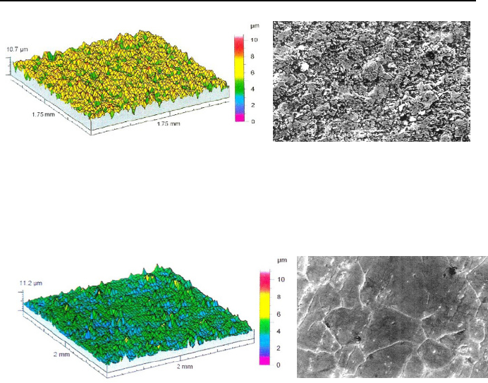
5.2.7 Non-traditional Machining Operations
The EDM process produces the spark-machined surfaces having a matte appear-
ance similar to a shot-blasted surface. It consists of very small spherical craters as
a result of the metal being removed by individual sparks, as shown in Figure 5.19.
The finish is therefore non-directional and very suitable for holding a lubricant.
Surface finishes of 0.25
μm R
a
and better have been obtained, typically 0.8−3.2
μm
(a)
(b)
Figure 5.17. Scanned topography (a) and optical image at a magnification of 300× (b) of
surfaces after cylindrical-plunge grinding of 42HRC low alloy steel with a 38
A 60
K 5
V
BE 43 grinding wheel at v
c
=
31
m/s, v
w
=
0.52
m/s and infeed f
r
=
0.006
mm/rev. Roughness
parameters: S
a
=
0.478
μm, S
t
=
4.72
μm, S
sk
=
−0.322, S
ku
=
3.3, surface structure-random
anisotropic, isotropic content −
13.8%
(a)
(b)
Figure 5.18. Scanned topography (a) and optical image at a magnification of 200× (b) of
surfaces after surface grinding on a vertical-spindle grinder of 65HRC low alloy steel with
a 38
A 60
K 5
V BE 43 grinding wheel at v
c
=
31
m/s, v
w
=
0.48
m/s and axial feed
f
a
=
0.008
mm/rev. Roughness parameters: S
a
=
0.2
μm, S
t
=
2.71
μm, S
sk
=
−1.58, S
ku
=
7.15,
surface structure-random anisotropic, isotropic content −6.19%.
5 Surface Integrity of Machined Surfaces 159
in finishing and 6.3−12.5
μm in roughing EDM operations. Irregularities have
small radii of peaks, about 2−10
μm, and they are inclined at relatively large angles
(RΔq is between 10−30°). These profile characteristics cause the bearing ratio of
the EDM profile to be extremely low. The random surface texture is created by
individual electric sparks and is termed as point (P) [7, 8].
After ECM, the initial surface texture disappears fully during the electrochemi-
cal dissolution and its influence on the final state of the surface can be neglected.
The height of irregularities depends mainly on the current density, and decreases
when this parameter increases. The surface texture is undetermined and the surface
produced is matte or semi-matte. The obtainable value of R
a
is between 0.32 to
1.25
μm. Very soft peaks, in comparison to milled and ground surfaces, with radii
of 90−220
μm, are produced within the surface profile. Typically, they are charac-
terized by the RΔq parameter between 2°30’ and 8°. The bearing curve is similar to
that for ground surfaces.
Figure 5.20 presents exemplary surface topography and optical image of ECM
surfaces under defined operation conditions, along with sets of appropriate 3D
roughness parameters and characteristic surface features.
(a)
(b)
Figure 5.19. Scanned topography (a) and optical image at a magnification of 200× (b) of
surfaces after WEDM of tungsten carbide with current I
=
8 A, voltage V
=
80
V, impulse time
t
imp
=
0.6
μs, interval time t
int
=
4.3
μs. Roughness parameters: S
a
=
1.03
μm, S
t
=
10.7
μm,
S
sk
=
−0.465, S
ku
=
3.47, surface structure-random anisotropic, isotropic content −56.6%.
(a)
(b)
Figure 5.20. Scanned topography (a) and optical image at magnification 150× (b) of
surfaces after ECM of special alloy U-500 with current I=1500 A, voltage V=12
V, NaCl
electrolyte. Roughness parameters: S
a
=
0.662
μm, S
t
=
11.2
μm, S
sk
=
−1.61, S
kuv
=
6.65,
surface structure-random anisotropic, isotropic content −37.2%.
160 W. Grzesik, B. Kruszynski, A. Ruszaj
5.3 Strain Hardening and Microstructural Effects in Machining
5.3.1 Physical Background
In metal cutting, the chip formation area consisting of three characteristic zones I−III
can be schematically presented as in Figure 5.3(a). The extensive primary defor-
mation (PDZ) zone is distinguished within this area by a number of slip lines includ-
ing the entry boundary on which plastic deformation begins and the exit boundary on
which chip material is entirely work hardened. A material particle during deforma-
tion is more intensively deformed between the shear band and the upper boundary.
Then, the material adjacent to the tool chip interface is subsequently deformed in
some depth due to intensive interfacial friction. The relevant region is called the
secondary deformation (SDZ). Additionally, the tertiary deformation zone (TDZ)
localized below the cutting edge in depth corresponding to the thickness of subsur-
face layer is separated.
In general, the shear yield strength in cutting exceeds the shear yield strength of
a bulk material by a factor of 2−4, depending on the intensity of plastic deforma-
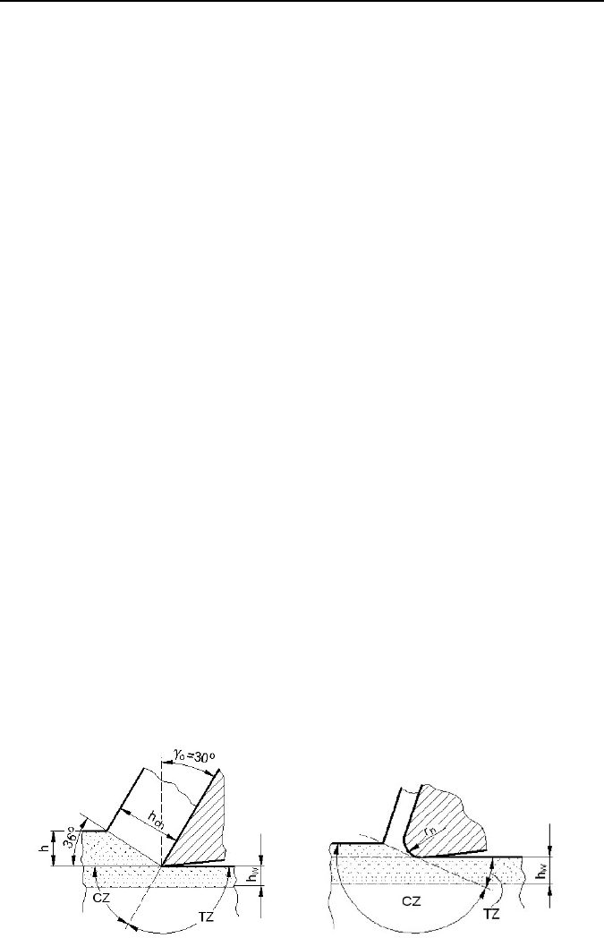
tion in the primary deformation zone (PDZ). As shown in Figure 5.21, the cutting
edge radius (in general, cutting-edge preparation) and the rake angle are predomi-
nant factors controlling the distribution of elastic stresses in the subsurface layer.
As shown in Figure 5.21(b), the compressive zone expands visibly when cutting
with rounded cutting edge (higher ratio of the cutting edge radius r
n
to unde-
formed chip thickness h) and larger negative rake angles. As a consequence, in
such cases the work-hardening effect will probably be more intensive due to the
plowing effect.
Figure 5.21 demonstrates that the machined surface is formed by fracture under
shearing stress. With ductile metals and alloys, both sides of a shear fracture are plas-
tically strained, so that some degree of plastic strain is an obvious feature of ma-
chined surfaces. The amount of strain and the depth below the machined surface to
which it extends can vary greatly, depending on the material being cut, the tool geo-
metry, and the cutting conditions, including the presence or absence of a lubricant.
In grinding, the high cutting speeds result in temperatures at the grain tip that
(a)
(b)
Figure 5.21. Distribution of stresses in the subsurface layer for sharp (a) and rounded (b)
cutting edge [4, 9]. CZ compressive zone, TZ tensile zone.
5 Surface Integrity of Machined Surfaces 161
may be as high as 1700°C. Moreover, 60 to 90% of the total energy consumed in
grinding flows instantaneously into the workpiece, causing rapid local increases in
temperature. As a result, various forms of thermal damage such as dimensional
errors, material structural changes, burning and surface cracking and high tensile
residual stresses can occur in grinding [10]. These effects can also occur, but not so
intensively, in machining operations with tools with geometrically defined geome-
tries, especially in dry, hard and HSM processes of difficult-to-machine materials
(hardened steels, austenitic stainless steels, titanium-based alloys, nickel- and co-
balt-based superalloys).
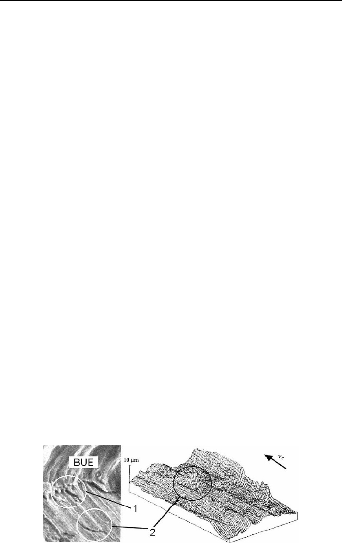
5.3.2 Built-up-edge Phenomenon
Under some machining conditions, usually at cutting speeds ranging from 30 to
60
m/min, the severe friction between the chip and the tool causes that the chip
material welds itself to the tool face and forms a pile of material, which is referred
to as a built-up-edge (BUE). Imaginarily, built-up formation is similar to what
happens when you walk through mud. Due to extreme work hardening, the hard-
ness of the BUE when machining steels is about 600−650
HV or more. Often the
built-up-edge continues to grow and then breaks up when it becomes unstable and
the broken pieces are carried away by the underside of the chip and randomly
deposited on the new workpiece surface. Figure 5.22 shows these mechanisms and
the rough workpiece surface with characteristic leaps. One cycle including for-
mation, growing and breaking up takes about 0.01−0.02
μs, which means that
10−500 leaps of 2−30
μm in height can be formed on the machined surface.
The built-up formation is commonly observed when form turning, broaching,
reaming and threading using uncoated high-speed steel tools at relatively low cut-
ting speeds. The BUE is one of the principal factors adversely affecting surface
finish. The gradual growth and rapid decay of the size of the BUE causes
a sawtoothed surface, which is characteristic of the BUE component of surface
roughness. In addition, the cutting tip becomes larger and the desirable diameter of
the workpiece changes when a built-up-edge is present. It should be noted that
apart from BUE sharp debris occurs on the part of the machined surface where
cutting tool loses contact with the workpiece.
Figure 5.22. SEM image of built-up-edge formation and its transfer on the machined sur-
face. 1 − place where BUE breaks down, 2 − leap on the machine surface.