Paulo D.J. Surface Integrity in Machining
Подождите немного. Документ загружается.

3 Residual Stresses and Microstructural Modifications 81
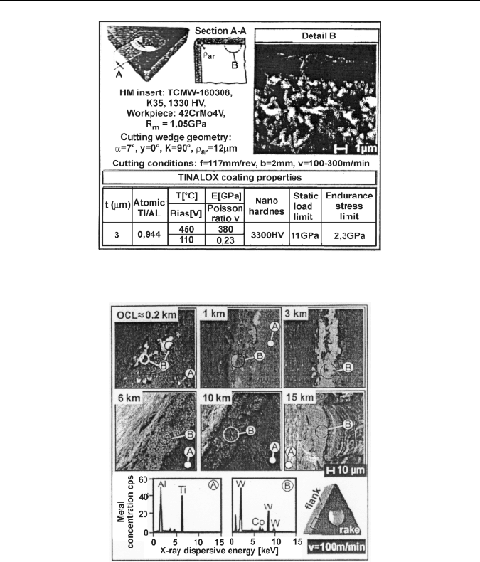
sure of substrate components, i.e., tungsten and cobalt. The failed zones are grow-
ing slowly through the increasing of the cutting length, as can be observed in the
related micrographs after 1, 3, 6, 10 and 15
km overall cutting length, whereas the
flank wear also increases.
3.3.4 Influence of Flank Wear on Residual Stress Formation
Chen et al. [22] presented modeling of flank wear land and chip formation on re-
sidual stresses below the machined surface of titanium alloy Ti-6A-4
V. The work-
piece was annealed at 700°C for 4 h and air cooled to provide a hardness of 35
Figure 3.14. Material microstructure and properties of the coated inserts, used in the ex-
periments [21]
Figure 3.15. SEM and EDX results indicating the progress of the coating failure at v
=
100
m/min [21]

82 J. Grum
±2HRC. The cutting tests were performed with an uncoated carbide tool with cut-
ting speed 320
m min
−1
and width of cut 1.0
mm. The tool’s rake and clearance
angles were +5 deg and +8 deg. It dry cutting environment was used in the tests. At
tool wear 0.03
mm and 0.20
mm samples for the residual stress measurements of
the machined surfaces were obtained. Depth residual-stress profiles were obtained
by the X-ray diffraction technique and removal of thin layers by electrolytic etch-
ing. The X-ray diffraction apparatus has a beam size of 4
mm × 4
mm; the radiation
source employed was CuKα.
The residual-stress profile is dependent on the cutting speed and flank wear
length at a cutting speed 320
m min
−1
. When the tool flank wear was 0.20
mm,
residual tensile stresses were found near the surface, with the maximum value
measured at the surface. Within less than 5
μm, from the newly machined surface,
the tensile residual stresses drop to zero. When the tool flank wear was 0.03
mm,
the residual-stress profile was different when compared with the larger flank wear
length. The residual stresses on the surface were compressive and the maximum
residual compressive stresses were found −10
μm from the surface. With the
smaller flank wear length, no tensile residual stresses were observed. In general,
thermal loading usually induces residual tensile stress and mechanical loading
causes residual compressive stresses. When the tool is worn, a higher temperature
is generated along the tool workpiece interface when compared to a sharp tool.
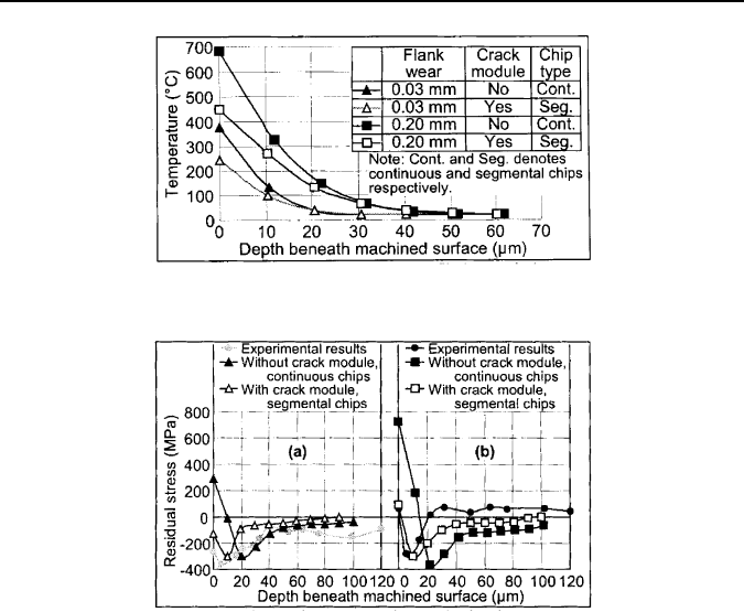
Figure 3.16 shows the temperature distribution below the surface on modeling.
Higher temperature and penetration depths were observed with continuous chip
when compared to a segmented type. For continuous chip, the proportion of heat
energy flowing into the workpiece was 17%, whereas for segmental chip it de-
creased from 10% to 13% due to the steeper shear angle. In general, heat energy
flows into the workpiece increased for lower shear angle. Therefore, the shear
angle is lower for a continuous chip than for a segmented chip. When the tool is
worn the temperature generated in the workpiece was higher when compared to
a sharp tool.
Figure 3.17 shows the influence tool wear and chip formation on residual-stress
distribution below the surface. When modeling without the crack module, continu-
ous chips will be formed and residual stress on the surface will be tensile and fol-
lowed by a more compressive residual stress. The more tensile residual stress was
due to higher temperature field found in the workpiece material with continuous
chip. The higher compressive residual stress was due to higher forces generated
with continuous chip. Therefore with segmental chips, the surface residual stress
was less tensile and the compressive stresses magnitude and depth were lowered.
The modeled residual stress with segmental chips agrees better with experimental
results during the cutting tests.
At flank wear ranging from 0.03
mm to 0.20
mm, the surface residual stress
tends to the tensile region. This was due to the higher temperature generated along
the tool workpiece interface, as shown in Figure 3.16. Similarly, the compressive
stress penetrates deeper with the worn tool.
The finite-element models presented in this paper can predict the effects of tool
wear and chip formation on temperature field, and residual stress distribution. The
modeled residual stress agrees well with their experimental results.
3 Residual Stresses and Microstructural Modifications 83
Figure 3.16. Temperature profile below the surface [22]
Figure 3.17. Effects of chip formation and (a) 0.03
mm and (b) 0.20
mm flank wear length
on residual-stress profile [22]
3.3.5 Residual Stresses After Dry Turning
Outeiro et al. [23] discussed critical issues in difficult cutting materials that are
often associated with short tool life and poor surface integrity, where the resulting
tensile residual stresses on the machined surface fatigue life. Their study presents
the influence of cutting parameters on surface integrity after dry turning of In-
conel 718 and austenitic stainless steel with PVD-coated (TiAlN) and uncoated
carbide tools.
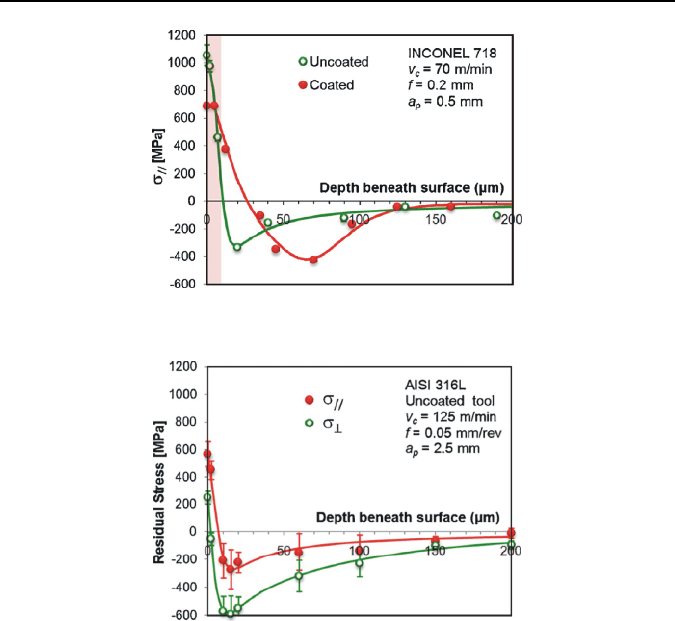
Figure 3.18 shows residual-stress profiles in the surface layer induced by cutting
with coated and uncoated cutting tools in the direction of primary motion. The
figure shows residual-stress profiles in the surface layer in the direction of feed
motion. Residual stresses are tensile at the surface and gradually shift to compres-
sive values beneath the surface at the level corresponding to that in the work mate-
rial before cutting. For the range of cutting conditions investigated, the residual
stresses were tensile over 1000
MPa at the surface. The figure also shows that cut-
ting with uncoated tools, when compared with the coated tools results in:
• higher surface residual stresses;
• lower thickens of tensile layer; and
• lower residual stresses in the surface layer with the maximum being shifted
closer to the surface in cutting with uncoated tools.
84 J. Grum
Figure 3.18. Residual-stress profiles in the direction of primary motion turning Inconel 718
[23]
Figure 3.19. Residual-stress profiles after turning stainless steel AISI 316L [23]
Regarding cutting conditions investigated, residual-stress profiles generated by
turning AISI 316L are also high tensile value at the surface, although not as high as
those obtained by Inconel 718. As shown in Figure 3.19 both residual stresses are
similar to those profiles observed in cutting profiles of Inconel 718.
3.3.6 Residual Stresses and Microstructures After Hard Turning
Byrne et al. [24] studied the functional behavior of machined parts that is strongly
influenced by the fine finishing processes. High flexibility and the ability to manu-
facture demanding shapes of workpieces represent the main advantages of hard
turning over grinding. The residual-stress values at the surface of the workpiece are
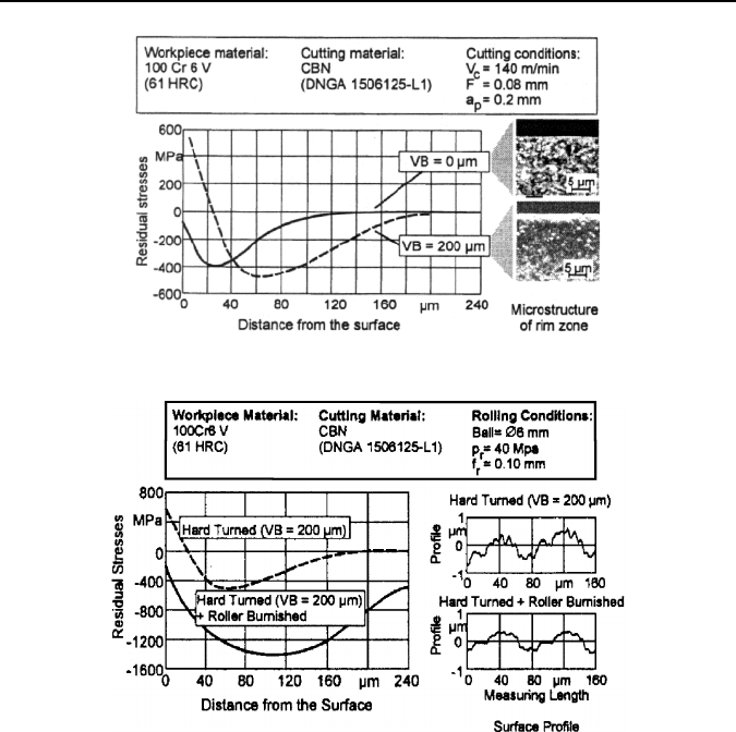
mainly influenced by the friction between the workpiece and the tool. Figure 3.20
shows residual-stress profiles at hard turning with different state of tool VB
=
0
μm
and VB
=
200
μm.
With an increasing flank wear the thermal load to the workpiece surface rises.
A new cutting tool induces compressive residual stresses below the workpiece
surface, whereas a worn tool causes tensile residual stresses and the appearance of
a white layer with a very fine microstructure.
3 Residual Stresses and Microstructural Modifications 85
Figure 3.20. Residual stress and surface layer effects after hard turning [24]
Figure 3.21. Surface layer effects due to roller burnishing [24]
Figure 3.21 shows residual-stress profiles at hard turning at tool wear VB =
200 μm and hard turning and roller burnishing at the surface.
For decades, low levels of lead have been added to free cutting and engineering
steels to improve their machinability. In recent years the use of lead has become
undesirable for environmental reasons. There has been great interest in the devel-
opment of materials with alternative machinability enhancers as well as demands
on the new additives that will not diminish the machining performance.
Dahlman et al. [25] researched the influence of rake angle and cutting parame-
ters on residual stresses in hard turning. Hard turning is replacing grinding as
a method in the production of precision steel products. Many researchers studied
the effects on the residual stress and the improvement of the fatigue life of hard
turned products. Face turning with constant cutting speed and changing of feed rate
and cutting depth in AISI 52100 steel was used. The residual stresses were meas-
ured using the X-ray diffraction method in both speed and feed direction. The ma-
terial was etched down to a depth of 100 μm in order to monitor residual stresses in
the whole of the affected depth.
86 J. Grum
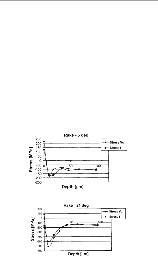
Figure 3.22 shows residual-stress profiles below the surface for cutting speed di-
rections. The residual stresses were tensile at the surface for different rake angles.
However, at a depth of about 5−10
μm, only compressive stresses could be ob-
served. With an effective rake angle of −6°, the maximum compressive stresses
were affected by the machining operation was about 30
μm at which point the
stresses left from the heat-treatment operation leveled out at –100
MPa. The mate-
rial used in this study was hardened steel, AISI 52100 with the hardness 62 HRC.
Rings with an outer diameter of 340
mm and an inner diameter of 180
mm were
turned on the face.
Figure 3.23 shows residual-stress profiles below the surface for cutting speed
and feed directions on cutting with a tool rake angle of –21°.
When the effective rake angle was decreased to –21°, two phenomena occurred.
Firstly, the level of compressive stresses increased to 500
MPa in the feed direction
and 600
MPa in the speed direction, the position of the maximum compressive
stress was still at 15
μm. Secondly, the affected depth increased to 40
μm.
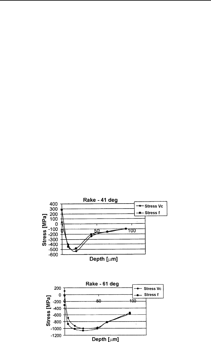
Figure 3.24 shows residual-stress profiles at turning with a tool at rake angle
–41°. The depth that the residual stress level was much greater, at almost 90
μm.
The position of the maximum residual stresses moved deeper to a depth of 25
μm.
Figure 3.25 shows the effects of a rake angle of –61 on residual-stress profiles
below the surface. In the feed direction, the maximum compressive stress was as
high as 1050
MPa 30
μm below the surface. At a measuring depth of 100
μm below
the surface the residual stress was approximately –550
MPa in both directions.
Figure 3.22. Residual stresses at a rake angle of –6° [25]
Figure 3.23. Residual stresses at a rake angle of –21° [25]
3 Residual Stresses and Microstructural Modifications 87
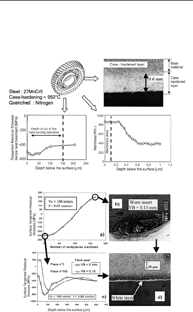
Rech and Moisan [26] presented surface integrity in finish hard turning of case-
hardened steels. They investigated gear canebrakes in a hard turning process in
mass production. Gear canebrakes are made of case-hardened 27 MnCr5 steel. The
cementation process provides an 850 HV03 hardness on the surface and affects
about 0.6
mm in depth, as shown in Figure 3.26.
The carbon composition of the case-hardened layer is nearly constant to the
0.3
mm regular depth. The carbon content in the layer is modified to 1% carbon.
The case hardening also modifies the residual stress profile, inducing compres-
sive residual stresses. The removed depth of cut is 0.15 mm with turning operation
before heat treatment. As one can observe the surface discovered by the hard turn-
ing operation should still have a 850 HV0.3 hardness and a tangential external
residual stress of –400 MPa if the cutting process did not affect the machined sur-
face.
Residual stresses profiles are presented in Figures 3.27 and 3.28.
Residual stresses are the results of three effects: mechanical, thermal, and metal-
lurgical. In hard turning, these three effects are governed by properties of tool ma-
terial and coatings, and their geometry including wear at various machining pa-
rameters. The changes in the physical properties of the workpiece surface due to
hard turning have to be attributed to the cutting force and to the cutting tempera-
ture. In order to compare the changes caused by hard turning, it is essential to ana-
lyze the corresponding chip-formation mechanism. In the area around the tip of the
cutting edge, the compressive stress levels must be very high. The high level of
mechanical stress being exerted on the surface of the workpiece tends to induce
compressive residual stresses.
Figure 3.24. Residual stresses at a rake angle of –41° [25]
Figure 3.25. Residual stresses at a rake angle of –61° [25]
88 J. Grum
Thermal stresses result mainly from the friction between the wear land VB and
the workpiece. The high direct stress levels cause high tangential stress that, in
conjunction with the relative motion between cutting edge and workpiece, results
in high levels of friction energy.
A typical residual stress profile in the tangential direction is shown in Fig-
ure 3.27(a). For a new insert and a cutting speed of 100
m/min, the surface residual
Figure 3.26. Properties of the machined surface after case hardening [26]
Figure 3.27. Influence of flank wear on the profile of residual stresses after hard turning [26]
3 Residual Stresses and Microstructural Modifications 89
stress is about −250
MPa. Beneath the surface the profile decreases to −800
MPa at
70
μm mm below the surface and then increases to the level of the bulk material
(−400
MPa).
Figure 3.27(c) shows the influence of flank wear on the residual-stress profile.
One can observe that the surface residual stress increases with flank wear and the
maximum compressive residual stress shifts further below the surface.
Flank wear increases the level of friction energy and thus cutting temperatures.
This indicates that a new cutting tool generates a compressive residual stress at the
surface, whereas a worn tool tends to generate a tensile residual stress at the surface.
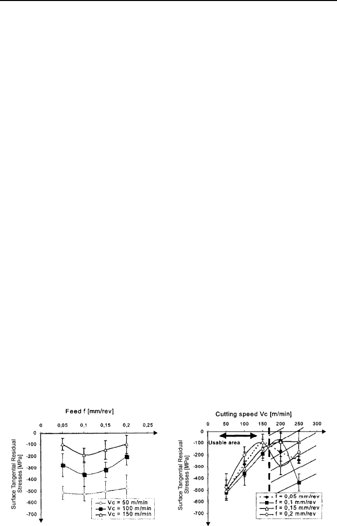
Figure 3.28(a) also shows the effect of feed rate on the residual stresses in the
tangential direction. In the range of 0.05 to 0.1
mm/rev, the residual stresses near
the surface shifted towards compression as feed rate was increased. On the other
hand, in the range of 0.1 to 0.2
mm/rev, the residual stresses near the surface re-
duced the comparison stress with increasing feed rate towards tension. Fig-
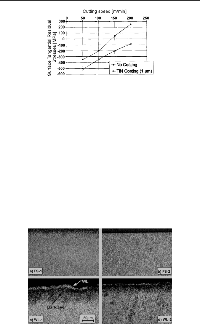
ure 3.28(b) shows the evolution of the surface tangential residual stress as a func-
tion of the cutting speed for an uncoated CBN insert and for a TiN-coated CBN
insert. TiN coating tends to decrease the surface residual stress between 150 and
350
MPa. The benefit of a coating is more important regarding the residual stress
level for high cutting speeds. This improvement may be attributed to the good
tribological behavior of TiN coating, which decreases the cutting friction energy
and the mean cutting temperature at the tool chip interface.
Figure 3.29 shows the evolution of the surface tangential residual stress as a
function of the cutting speed for different feed rates. One can observe that cutting
speed tends to increase the surface residual stress, irrespective of the feed rate in
the range of 50 to 150
m/min. On the other hand, the evolution of the curves
changes above 200
m/min. It has to be noticed that the values of the residual
stresses produced with cutting speeds of 200 and 250
m/min are not suitable for
mass production.
Schwach et al. [27] presented surface integrity at hard turning on rolling contact
fatigue. Hard turning normally produces favorable surface integrity that would
improve component life in rolling contact.
Effects of the process-induced residual stress profile and the white layer on roll-
ing contact fatigue (RCF) are poorly understood.
(a) (b)
Figure 3.28. Influence of the cutting conditions on the residual stresses after hard turning at
various cutting speeds (a) and feed rates (b) [26]
90 J. Grum
Figure 3.29. Influence of the TiN coating on surface residual stress after hard turning [26]
This study explains how residual stress and the white layer affect RCF. Based
on the developed real-time RCF testing system, a series of RCF tests were con-
ducted on hard-turned AISI 52100 steel specimens. A white layer induced by hard
turning is very detrimental to RCF and reduce component life by six times. Resid-
ual-stress profiles are significant factors for RCF, while the depth of maximum
compressive residual stress in the subsurface is not critical.
The flat-disc work specimens of AISI 52100 were heat treated to 61−62
HRc.
Specimens were turned in a facing operation to maintain a constant cutting velocity
as the cutting tool approached the center of the specimens. Four different machin-
ing conditions were used to produce distinct surface integrities; the same cutting
tool (GE Super-abrasives BZN 8100 compact insert with a 0.015/15° chamfer and
a radius of 6.35
mm) was used in all four machining conditions.
A novel design of a RCF testing system design was utilized in this experimental
study. The test specimen is secured in a plate that rests upon a load cell and is posi-
tioned by four rods secured to the work table. Acoustic emission (AE) was used for
fatigue monitoring and detection.
Figure 3.30 shows surface microstructure of the machined specimens. The spec-
imens without white layers specimens (FS-1 and FS-2) show a uniform microstruc-
Figure 3.30. Surface microstructure of the machined specimens [27]