Patrick F. Dunn, Measurement, Data Analysis, and Sensor Fundamentals for Engineering and Science, 2nd Edition
Подождите немного. Документ загружается.


36 Measurement and Data Analysis for Engineering and Science
2.7 *Equivalent Circuits
Th´evenin’s equivalent circuit theorem states that any two-terminal
network of linear impedances, such as resistors and inductors, and voltage
sources can be replaced by an equivalent circuit consisting of an ideal voltage
source, E
T h
, in series with an impedance, Z
T h
. This circuit is shown in the
top of Figure 2.12.
Norton’s equivalent circuit theorem states that any two-terminal
network of linear impedances and current sources can be replaced by an
equivalent circuit consisting of an ideal current source, I
T h
, in parallel with
an impedance, Z
T h
. This circuit is illustrated in the bottom of Figure 2.12.
The voltage of the Th´evenin equivalent circuit is the current of the Nor-
ton equivalent circuit times the equivalent impedance. Obtaining the equiv-
alent impedance sometimes can be tedious, but it is very useful in under-
standing circuits, especially the more complex ones.
The Th´evenin equivalent voltage and equivalent impedance can be
determined by examining the open-circuit voltage and the short-circuit cur-
rent. The Th´evenin equivalent voltage, E
T h
, is the open-circuit voltage,
which is the potential difference that exists between the circuit’s two ter-
minals when nothing is connected to the circuit. This would be the voltage
measured using an ideal voltmeter. Simply put, E
T h
= E
oc
, where the sub-
script oc denotes open circuit. The Th´evenin equivalent impedance,
Z
T h
, is E
th
divided by the short-circuit current, I
sc
, where the subscript
sc denotes short circuit. The short-circuit current is the current that would
pass through an ideal ammeter connected across the circuit’s two terminals.
An example diagram showing an actual circuit and its Th´evenin equiv-
alent is presented in Figure 2.13. In this figure, Z
T h
is represented by R
T h
because the only impedances in the circuit are resistances. R
m
denotes the
meter’s resistance, which would be infinite for an ideal voltmeter and zero
for an ideal ammeter.
The Th´evenin equivalents can be found for the actual circuit. Kirchhoff’s
voltage law implies
E
i
= I(R
1
+ R
2
). (2.44)
Also, the voltage measured by the ideal voltmeter, E
m
, using Ohm’s law
and noting that R
2
<< R
m
, is
E
m
= E
th
= IR
2
. (2.45)
Combining Equations 2.44 and 2.45 yields the open-circuit or Th´evenin
equivalent voltage,
E
T h
= E
i
R
2
R
1
+ R
2
. (2.46)

Electronics 37
FIGURE 2.13
A circuit and its Th´evenin equivalent.
Further, the short-circuit current would be
I
sc
= E
i
/R
1
. (2.47)
So, the Th´evenin equivalent resistance is
R
T h
≡
E
T h
I
sc
=
R
1
R
2
R
1
+ R
2
. (2.48)
The resulting Th´evenin equivalent circuit is shown in the bottom of Figure
2.13.
An alternative approach to determining the Th´evenin impedance is to
replace all voltage sources in the circuit by their internal impedances and
then find the circuit’s output impedance. Usually the voltage sources’ in-
ternal impedances are negligible and can be assumed to be equal to zero,
effectively replacing all voltage sources by short circuits. For the circuit
shown in Figure 2.13, this approach would lead to having the resistances R
1
and R
2
in parallel to ground, leading directly to Equation 2.48.
This alternative approach can be applied also when determining the
Th´evenin equivalent resistance, which is the output impedance, of the

38 Measurement and Data Analysis for Engineering and Science
Wheatstone bridge circuit shown in Figure 2.10. Assuming a negligible in-
ternal impedance for the voltage source E
i
, R
T h
is equivalent to the parallel
combination of R
1
and R
2
in series with the parallel combination of R
3
and
R
4
. That is,
R
T h
=
R
1
R
2
R
1
+ R
2
+
R
3
R
4
R
3
+ R
4
. (2.49)
Example Problem 2.6
Statement: For the circuit shown in the top of Figure 2.13, determine the Th´evenin
equivalent resistance and the Th´evenin equivalent voltage, assuming that V
s
= 20 V,
R
1
= 6 Ω, R
2
= 3 Ω, and R
m
= 3 MΩ.
Solution: Because R
m
>> R
2
, the Th´evenin equivalent voltage is given by Equation
2.46 and the Th´evenin equivalent resistance by Equation 2.48. Substitution of the given
values for V
s
= E
i
, R
1
, and R
2
into these equations yields E
th
= (20)
h
3
6+3
i
= 6.67 V
and R
th
=
(6)(3)
6+3
= 2 Ω.
2.8 *Meters
FIGURE 2.14
Voltage and current meters.
All voltage and current meters can be represented by Th´evenin and
Norton equivalent circuits, as shown in Figure 2.14. These meters are char-
acterized by their input impedances. An ideal voltmeter has an infinite
input impedance such that no current flows through it. An ideal amme-
ter has zero input impedance such that all the connected circuit’s current
flows through it. The actual devices differ from their ideal counterparts
only in that the actual impedances are neither zero nor infinite, but finite.

Electronics 39
A voltmeter is attached in parallel to the point of interest in the circuit. An
ammeter is attached in series with the point of interest in the circuit. A good
voltmeter has a very high input impedance, typically greater than 1 MΩ.
Because of this, a good voltmeter connected to a circuit draws negligible
current from the circuit and, therefore, has no additional voltage difference
present between the voltmeter’s terminals. Likewise, because a good amme-
ter has a very low input impedance, typically less than 1 Ω, almost all of
the attached circuit’s current flows through the ammeter.
Resistance measurements typically are made using an ohmmeter. The
resistance actually is determined by passing a known current through the
test leads of a meter and the unknown resistance and then measuring the
total voltage difference across them. This is called the two-wire method.
This approach is valid provided that the unknown resistance is much larger
than the resistances of the test leads. In practice, this problem is circum-
vented by using a multimeter and the four-wire method. This method
requires the use of two additional test leads. Two of the leads carry a known
current through the unknown resistance and then back to the meter, while
the other two leads measure the resulting voltage drop across the unknown
resistance. The meter determines the resistance by Ohm’s law and then
displays it.
2.9 *Impedance Matching and Loading Error
When the output of one electronic component is connected to the input of
another, the output signal may be altered, depending upon the component
impedances. Each measurement circumstance requires a certain relation be-
tween the output component’s output impedance and the input component’s
input impedance to avoid signal alteration. If this impedance relation is not
maintained, then the output component’s signal will be altered upon connec-
tion to the input component. A common example of impedance mismatch
is when an audio amplifier is connected to a speaker with a high input
impedance. This leads to a significant reduction in the power transmitted
to the speaker, which results in a low volume from the speaker.
A loading error can be introduced whenever one circuit is attached
to another. Loading error, e
load
, is defined in terms of the difference be-
tween the true output impedance, R
true
, the impedance that would be mea-
sured across the circuit’s output terminals by an ideal voltmeter, and the
impedance measured by an actual voltmeter, R
meas
. Expressed on a per-
centage basis, the loading error is
e
load
= 100
R
true
− R
meas
R
true
. (2.50)

40 Measurement and Data Analysis for Engineering and Science
FIGURE 2.15
Voltage circuit (top) and current circuit (bottom) illustrating loading error.
Loading errors that occur when measuring voltages, resistances, or cur-
rent can be avoided by following two simple rules. These rules, summarized
at the end of this section, can be derived by considering two circuits, one in
which an actual voltage source circuit is connected to an actual voltmeter,
and the other in which an actual current source circuit is connected to an
actual ammeter. These circuits are shown in Figure 2.15.
For the voltage circuit, Kirchhoff’s voltage law applied around the outer
circuit loop gives
V
m
= V
s
− I
o
R
out
. (2.51)
Kirchhoff’s current law applied at node A yields
I
o
= I
A
= V
m
/R
in
, (2.52)
where all of the current flows through the voltmeter’s R
in
. Substituting
Equation 2.52 into Equation 2.51 results in
V
m
= V
s
1
1 +
R
out
R
in
= V
s
R
in
R
in
+ R
out
. (2.53)
When R
in
>> R
out
, V
m
= V
s
. Noting for this voltage measurement case

Electronics 41
that R
true
= R
out
and R
meas
= (R
in
R
out
)/(R
in
+ R
out
), the loading error
becomes
e
load,V
=
R
out
R
in
+ R
out
. (2.54)
For the current circuit, Kirchhoff’s current law applied at node B yields
I
s
= I
B
+ I
o
. (2.55)
Kirchhoff’s voltage law applied around the circuit loop containing R
in
and
R
out
gives
I
m
R
in
= I
B
R
out
. (2.56)
Substituting Equation 2.56 into Equation 2.55 results in
I
m
= I
s
1
1 +
R
in
R
out
= I
s
R
out
R
in
+ R
out
. (2.57)
When R
in
<< R
out
, I
m
= I
s
. Noting for the current measurement case
that R
true
= R
in
and R
meas
= (R
in
R
out
)/(R
in
+ R
out
), the loading error
becomes
e
load,I
=
R
in
R
in
+ R
out
. (2.58)
Loading errors can be avoided between two circuits by connecting them
via a buffer that has near-infinite input and near-zero output impedances.
This is one of the many uses of operational amplifiers. These are presented
in Chapter 3.
Example Problem 2.7
Statement: Determine the minimum input impedance, R
min
, of a voltage measure-
ment circuit that would have less than 0.5 % loading error when connected to a circuit
having an output impedance of 50 Ω.
Solution: Direct application of Equation 2.54 implies
0.5
100
=
50 Ω
50 Ω + R
min
.
Solving for the minimum input impedance gives R
min
= 9950 Ω, or approximately 10
kΩ. This condition can be met by using a unity-gain operational amplifier in the non-
inverting configuration at the input of the voltage-measurement circuit (see Chapter
3).

42 Measurement and Data Analysis for Engineering and Science
The impedance relation for optimum power transmission between an
output source and an input circuit can be determined [8]. For the voltage
circuit in Figure 2.15, noting that the power received, P
in
, equals V
2
in
/R
in
,
Equation 2.53 becomes
P
in
= V
2
s
R
in
(R
in
+ R
out
)
2
. (2.59)
Differentiating Equation 2.59 with respect to R
in
, setting the result equal
to zero and solving for R
in
gives
R
in
= R
out
. (2.60)
Substitution of Equation 2.60 into the derivative equation shows that this
condition ensures a maximum transmission of power. Equation 2.60 rep-
resents true impedance matching, where the two impedances have the
same value.
Example Problem 2.8
Statement: Determine the power that is transmitted, P
t
, between two connected
circuits if the output circuit impedance is 6.0 Ω, the input circuit impedance is 4.0 Ω,
and the source voltage is 12 V.
Solution: Substitution of the given values into Equation 2.53 gives V
m
= 12
h
4
6+4
i
= 4.8 V. Now, the power transmitted is given by P
t
= V
2
in
/R
in
= 4.8
2
/4 = 5.8 W,
with the correct number of significant figures.
Impedance matching also is critical when an output circuit that generates
waveforms is connected by a cable to a receiving circuit. In this situation, the
high-frequency components of the output circuit can reflect back from the
receiving circuit. This essentially produces an input wave to the receiving
circuit that is different from that intended. When a cable with characteristic
impedance, R
cable
, is connected to a receiving circuit of load impedance,
R
in
, and these impedances are matched, then the the input wave will not
be reflected. The reflected wave amplitude, A
r
, is related to the incident
wave amplitude, A
i
, by
A
r
= A
i
R
cable
− R
in
R
cable
+ R
in
. (2.61)
When R
cable
< R
in
, the reflected wave is inverted. When R
cable
> R
in
, the
reflected wave is not inverted [2].
The rules for impedance matching and for loading error minimization,
as specified by Equations 2.53, 2.57, 2.60, and 2.61, are as follows:
• Rule 1 − loading error minimization: When measuring a voltage,
the input impedance of the measuring device must be much greater than
the equivalent circuit’s output impedance.

Electronics 43
• Rule 2 − loading error minimization: When measuring a current,
the input impedance of the measuring device must be much less than
the equivalent circuit’s output impedance.
• Rule 3 − impedance matching: When transmitting power to a load,
the output impedance of the transmission circuit must equal the input
impedance of the load for maximum power transmission.
• Rule 4 − impedance matching: When transmitting signals having
high frequency through a cable, the cable impedance must equal the
load impedance of the receiving circuit.
2.10 *Electrical Noise
Electrical noise is defined as anything that obscures a signal [2]. Noise
is characterized by its amplitude distribution, frequency spectrum, and the
physical mechanism responsible for its generation. Noise can be subdivided
into intrinsic noise and interference noise. Intrinsic noise is random and
primarily the result of thermally induced molecular motion in any resistive
element (Johnson noise), current fluctuations in a material (shot noise), and
local property variations in a material (1/f or pink noise). The first two
are intrinsic and cannot be eliminated. The latter can be reduced through
quality control of the material that is used.
Noise caused by another signal is called interference noise. Interference
noise depends on the amplitude and frequency of the noise source. Common
noise sources include AC-line power (50 Hz to 60 Hz), overhead fluorescent
lighting (100 Hz to 120 Hz), and sources of radio-frequency (RF) and elec-
tromagnetically induced (EMI) interference, such as televisions, radios, and
high-voltage transformers.
The causes of electrical interference include local electric fields, magnetic
fields, and ground loops. These noticeably affect analog voltage signals with
amplitudes less than one volt. A surface at another electric potential that is
near a signal-carrying wire will establish an undesirable capacitance between
the surface and the wire. A local magnetic field near a signal-carrying wire
will induce an additional current in the wire. A current flowing through one
ground point in a circuit will generate a signal in another part of the circuit
that is connected to a different ground point.
Most interference noise can be attenuated to acceptable levels by proper
shielding, filtering, and amplification. For example, signal wires can be
shielded by a layer of conductor that is separated from the signal wire by an
insulator. The electric potential of the shield can be driven at the same po-
tential as the signal through the use of operational amplifiers and feedback,

44 Measurement and Data Analysis for Engineering and Science
thereby obviating any undesirable capacitance [5]. Pairs of insulated wires
carrying similar signals can be twisted together to produce signals with the
same mode of noise. These signals subsequently can be conditioned using
common-mode rejection techniques. Use of a single electrical ground point
for a circuit almost always will minimize ground-loop effects. Signal ampli-
fication and filtering also can be used. In the end though, it is better to
eliminate the sources of noise than to try to cover them up.
The magnitude of the noise is characterized through the signal-to-noise
ratio (SNR). This is defined as
SNR ≡ 10 log
10
V
2
s
V
2
n
, (2.62)
where V
s
and V
n
denote the source and noise voltages, respectively. The volt-
age values usually are rms values (see Chapter 9). Also, a center frequency
and range of frequencies are specified when the SNR is given.
Electronics 45
2.11 Problem Topic Summary
Topic
Review Problems
Homework Problems
Basics
1, 2, 4, 6, 7, 13, 14, 15
8, 9, 10
20, 21, 22, 23, 24, 25
Circuits
3, 5, 8, 9, 10, 11, 12
4, 5, 7, 8, 11, 12
16, 17, 18, 19
Systems
8, 9, 10, 11
1, 2, 3, 6
Op Amps
23
13, 14
TABLE 2.2
Chapter 2 Problem Summary
2.12 Review Problems
1. Three 11.9 µF capacitors are placed in series in an electrical circuit.
Compute the total capacitance in µF to one decimal place.
2. Which of the following combination of units is equivalent to 1 J? (a) 1
C·A·W, (b) 1 W·s/C, (c) 1 N/C, (d) 1 C·V.
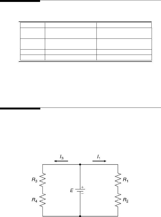
FIGURE 2.16
Electrical circuit.
3. For the electrical circuit depicted in Figure 2, given R
1
= 160 Ω, R
3
=
68 Ω, I
1
= 0.9 A, I
3
= 0.2 A, and R
2
= R
4
, find the voltage potential,
E, to the nearest whole volt.